Doosan DL300 Wheel Loader Factory Service & Shop Manual
Catalog:
Model:
Complete workshop repair service manual with electrical wiring diagrams for Doosan DL300 Wheel Loader. It's the same service manual used by dealers that guaranteed to be fully functional and intact without any missing page.
This Doosan DL300 Wheel Loader service & repair manual (including maintenance, overhaul, disassembling & assembling, adjustment, tune-up, operation, inspecting, diagnostic & troubleshooting…) is divided into different sections. Each section covers a specific component or system with detailed illustrations. A table of contents is placed at the beginning of each section. Pages are easily found by category, and each page is expandable for great detail. The printer-ready PDF documents work like a charm on all kinds of devices.
“K1010636E.pdf”
Doosan DL300 Wheel Loader Shop Manual
K1010636E; Serial Number 5001 and Up; 766 pages
TABLE OF CONTENTS
Safety
Wheel Loader Safety ......................... SP000095
Specifications
Specification for DL300...................... SP000104
General Maintenance
General Maintenance Procedures.............. SP000097
Standard Torques.......... SP000098
Drive Train
Transmission and Torque Converter ............. SP000118
Transmission Error Codes (ZF) ............... SP000100
Front Axle (ZF-MT-L 3095) ................... SP000199
Rear Axle (ZF-MT-L 3085).................... SP000217
Drive Shaft .............. SP000218
Brake
Service Brake ......... SP000219
Brake Supply Valve ....... SP000220
Parking Brake ......... SP000221
Brake Pedal Valve ......... SP000222
Accumulator............ SP000223
Steering
Steering ............... SP000224
Cushion Valve......... SP000328
Emergency Steering ...... SP000225
Frame
Articulation Center ......... SP000231
Counterweight......... SP000130
Tank
Oil Tank ............... SP000226
Fuel Tank............. SP000227
Hydraulics
Main Control Valve ........ SP000233
Load Isolation System ....................... SP000228
Cooling System....... SP000229
Pilot System............ SP000230
Hydraulic Schematic (DL300) ............... SP000234
Electrical System
Air Conditioner ........ SP000172
Electrical System ........... SP000268
Electrical Schematic (DL300) ............... SP000272
…
EXCERPT:
Drive Axle
The drive axle consists of differential, final reduction gear assembly, wet type hydraulic disk brake unit, and axle shafts to which wheels are attached.
The power from drive unit is transmitted through the drive shafts to front and rear drive axles. The power is then transmitted to differential where it is divided into right and left axle shafts to final reduction gear assembly on each shaft end, thus driving the wheels.
The wet type hydraulic disk brake unit is installed in front of final reduction gear assembly and serves as a service brake.
Axle Mount
The front axle is bolted directly to front frame.
The rear axle is supported by the trunnion method in which axle supports are installed across the rear axle and bolted to rear frame. Consequently, the rear axle is cradled up and down around the center line of differential according to ground condition the loader travels. The trunnion mounted drive axle helps improve operator comfort because loaders with a trunnion mounted drive axle jolt less than those with the conventional cradle supported drive axle, when they travel on bad ground conditions.
…
CENDL3000001..2
DL300 Electrical Wiring Diagram..3
K1010630E - DL300 Operation and Maintenance Manual..4
Presentation..10
Presentation..10
Intended Use..11
Engine..11
Electrical System..11
Power Transmission..11
Brake System..12
Parking Brake..12
Steering System..12
Cabin..12
FOPS and ROPS..12
Hydraulic System..12
Equipment..12
CE Marking, EMC Directive..13
CE Marking..13
The EU EMC Directive..13
Communication Equipment Installation..14
Protection Against Electromagnetic Interference..14
Product Plates..15
01-omK1010630E-48.pdf..0
Safety..16
To the Operator of a DOOSAN Daewoo Wheel Loader..16
Learn Signal Words Used With Safety Alert Symbol..17
General Safety Essentials..19
Accessory Applications..19
Location of Safety Labels..19
1. Warnings for Operation, Inspection and Maintenance (41902545A, 19000092)..21
2. Warnings for Cooling Fan (21903315, 19000557)..21
3. Warnings When Opening Engine Hood (21903315, 19000095)..22
4. Warnings for Using Wheel Block (41902547A, 19000207)..22
5. Warnings for Handling Accumulator (19000703, 19000099)..23
Accumulator..23
6. Keep Out of Steering Turn Area (41901992A, 19000120)..24
7. Warnings for High Temperature Hydraulic Oil (19000691, 19000097)..24
8. Warnings for High Temperature Coolant (19000692, 19000097)..25
9. Warnings for Battery Maintenance (19000537, 19000100)..25
10. Warnings for Performing Maintenance On Front Attachment (41902546A, 19000105)..26
11. Warnings to Use Safety Lock (41901993, 19000121)..26
12. Warning Tag (19000695, 19000098)..27
Unauthorized Modifications..28
General Hazard Information..28
Safety Rules..28
Safety Features..28
Inside Operator's Compartment..29
Clothing and Personal Protective Items..30
Breathing Masks, Ear Protection May Be Required..30
Vibration Level Information..30
Recommendations for Limiting Vibrations..30
Asbestos Dust Hazard Prevention..31
Mounting and Dismounting..32
Fuel, Oil and Hydraulic Fluid Fire Hazards..32
Precautions When Handling Fluids at High Temperature..33
Injury from Work Equipment..33
Fire Extinguisher and First Aid Kit..34
Protection from Falling or Flying Objects..34
Install Additional Safety Equipment If Conditions Require..35
Maintain Standard Safety Equipment in Good Condition..35
Attachment Precautions..35
Accumulator..36
Engine Ventilation..36
Before Starting Engine..37
Work Site Precautions..37
Checks Before Starting Engine..38
Engine Starting..38
Before Operating Machine..39
Machine Operation..41
Operate While Seated at Operator's Station Only..41
Seat Belts Must Be Used at All Times..41
Movement Alarms..41
Travel Precautions..42
Sloping Terrain Requires Caution..42
Avoid High Voltage Cables..43
Before Starting to Dig, Contact Authorities..43
Be Aware of Height Obstacles..43
Use Care on Loose Support..44
Use Solid Support Blocking..44
Digging Beneath Overhangs..44
Digging Beneath Wheel Loader..44
Stay Alert for People Moving Through Work Area..44
Be Aware of and Conform to Local Regulations..45
Never Use Ether Starting Aids..45
Observe General Safety Rules..45
Take Time to Provide Good Visibility..46
Keep "Pinch Point" Areas Clear Use Caution in Reverse..46
Operate Carefully on Snow and Ice, In Very Cold Temperatures..47
Parking Machine..47
Shutdown Control Functions..48
Never Let Anyone Ride on Attachment..48
Maintenance..49
Use Warning Tag During Service..49
Clean Before Inspection or Maintenance..49
Proper Tools..50
Use of Lighting..50
Fire Prevention and Explosion Prevention..50
Burn Prevention..51
Welding Repairs..51
Precautions for Removal, Installation, and Storage of Attachments..52
Precautions When Working on Machine..52
Lock Inspection Covers..53
Crushing Prevention and Cutting Prevention..53
Do Not Run Engine If Repairs or Work Are Being Performed Alone..53
Always Use Adequate Equipment Supports and Blocking..53
Do Not Work on Hot Engines or Hot Cooling or Hydraulic Systems..54
Hydraulic Cylinder Seals Require Periodic Replacement..54
Highpressure Hydraulic Lines Can Store a Great Deal of Energy..54
Cool Down Is Required Before Radiator or Reservoir Checks..54
Precautions with Highpressure Line, Tubes and Hoses..55
Obtain Immediate Medical Attention if Pressurized Oil Pierces Skin...56
Use Correct Replacement Fasteners Tightened to Proper Torque..56
Safety Critical Parts Must Be Replaced Periodically..56
Dispose of All Petroleum Based Oils and Fluids Properly..57
Check Tire Pressure and Condition..57
Decreasing Risk of Injuries or Death From Boom and Bucket..58
Battery..60
Battery Hazard Prevention..60
Disconnect Batteries Before Electrical Service or Electrical Welding..61
Use Low Heat Portable Lighting..61
Boost Starting or Charging Engine Batteries..61
Towing..62
Precautions When Towing..62
Shipping and Transportation..63
Obey State and Local OvertheRoad Regulations..63
02-omK1010630E-64.pdf..0
OP000036..64
Operating Controls..64
1. “Component Locations” on page 22..64
2. “Operator's Area” on page 24..64
3. “Steering Console and Pedals” on page 25..64
4. “Gauges” on page 216..64
5. “Gauges” on page 216..64
6. “Right Side Switch Panel” on page 226..64
7. “Various Cabin Locations” on page 241..64
8. “Heater and Air Conditioner Operation” on page 245..64
9. “Stereo / CD Player (Optional)” on page 250..64
10. “Seat Adjustment (Standard)” on page 252..64
11. “Seat Adjustment (Option)” on page 254..64
12. “Seat Belt” on page 256..64
13. “Door Side Latch” on page 257..64
14. “Fuse Box/Relay/Engine Emergency Stop Switch” on page 259..64
Component Locations..65
Figure 1..65
1..66
Bucket Teeth..66
2..66
Bucket..66
3..66
Air Conditioner Condenser..66
4..66
Rear Wheel Cover..66
5..66
Battery Box..66
6..66
Rear Light..66
7..66
Counterweight..66
8..66
Fan Motor..66
9..66
Towing Pin..66
10..66
Muffler Tail Pipe..66
11..66
Oil Tank..66
12..66
Tilt Lever..66
13..66
Front Wheel Cover..66
14..66
Bucket Cylinder..66
15..66
Headlight Support..66
16..66
Ladder..66
17..66
Work Light..66
18..66
Operator's Cabin..66
19..66
Air Cleaner..66
20..66
Engine Air Intake Precleaner..66
21..66
Engine..66
22..66
Muffler..66
23..66
CAC Cooler..66
24..66
Radiator..66
25..66
Grille..66
26..66
Fan..66
27..66
Fuel Tank..66
28..66
Engine Oil Fill Cap..66
29..66
Engine Oil Filter..66
30..66
Engine Oil Level Dipstick..66
31..66
32..66
Rear Axle..66
33..66
Drive Shaft (Rear)..66
34..66
Transmission..66
35..66
Transmission Oil Filter..66
36..66
Drive Shaft (Center)..66
37..66
Center Pin..66
38..66
Steering Wheel Cylinder..66
39..66
Boom Cylinder..66
40..66
Drive Shaft (Front)..66
41..66
Parking Brake..66
42..66
Front Axle..66
43..66
Loader Arm..66
44..66
Link..66
Operator's Area..67
Figure 2..67
Steering Console and Pedals..68
Figure 3..68
Figure 4..69
1. Starter Switch..69
A threeposition starter switch is used to start or shut down engine for equipment operation...69
O. Turning the switch to this position turns the engine "OFF" along with its electrical system. In this position the engine is "OFF" but the interior cabin light and fuel tank transfer pump (if equipped) are functional...69
I. Turning the switch to this position turns the engine electrical system "ON." When the switch is first turned "ON" the six indicator/warning lights across the top of the instrument panel, will light for approximately two seconds. The batter...69
NOTE: Preheat Indicator Light The operation of the preheat cycle depends on coolant temperature. When the engine coolant is cold enough, the preheat indicator light will remain "ON" until the engine preheat cycle is completed. The preheat cyc...69
. Moving switch to this position will crank engine. When engine starts, release key and allow it to return to the "I" (ON) position. Do not operate the starter switch for more than fifteen seconds at a time. This will help prevent damage to starter...69
Figure 5..70
2. Horn Button (Two Places)..70
Pressing the button at the end of the combination switch (Figure 5) or the left button at the tip of the pilot control valve lever (joystick) (Left) of the two levers (Figure 6), the horn will sound...70
NOTE: Starter switch must be "ON."..70
Figure 6..70
Figure 7..70
Figure 8..71
3. Combination Switch..71
A. Left Side Directional Switch Pushing lever forward, activates left outside directional lights and directional indicator light on instrument panel...71
B. Right Side Directional Switch Pulling lever back, activates right outside directional lights and directional indicator light on instrument panel...71
NOTE: When turn is completed the lever automatically returns to the "NEUTRAL" position. Should it not, it can be manually returned by hand...71
NOTE: Turn signals will function with starter switch in "OFF" position...71
C. Window Washer Switch When the outside area of the lever is pressed, it activates the washer pump and sprays fluid on the windshield. (Only while being pressed.)..71
NOTE: Do not operate the windshield washer without any fluid. If operate without any fluid, the washer motor may be damaged. Check level in washer tank, and add fluid as required...71
NOTE: Using soapy water or synthetic detergent instead of window cleaning fluid, may damage the wiper blade or painted surfaces. Use standard window cleaning fluid: SSK703..71
D. Horn Button The center button on end of lever activates horn. (Only while being pressed.)..71
E. Wiper Switch Activates wipers when outside area of lever is rotated...71
J: Intermittent Mode wipes every five seconds...71
0: Stop (Off)...71
I: Normal Speed Mode...71
II: High Speed Mode...71
Figure 9..71
F. Push Down Locks into position and light turns "ON" the high beams...71
G. Neutral Position Normal low beams...71
H. Pull Up Momentarily turns "ON" both the low beams and high beams. (Returns to "NEUTRAL" position when released.)..71
NOTE: High and low beams will only function with the headlight switch in the "||" position...71
Figure 10..72
4. Accelerator Pedal..72
Controls the travel speed of loader and working speed of load handling system...72
Figure 11..73
5. Steering Wheel Adjustment Lever..73
Control lever (1, Figure 11) is used allow wheel to be moved to the most convenient position for the operator...73
Adjusting Steering Wheel Tilt..73
Pull lever (1, Figure 12) upward and move wheel (2, Figure 12) to desired position. Push lever down (Tilt angle is 21°)...73
Adjusting Steering Wheel Telescopic..73
Pull lever (1, Figure 12) upward and move wheel (2, Figure 12) to desired position. Push lever down (telescopic stroke is 80 mm)..73
Figure 12..73
Figure 13..73
6. Brake Pedal (Right and Left Pedals)..73
Pressing brake pedal will apply the brakes to the loader. The brake pedal modes can be switched from "INCHING" to "NO INCHING" or vice versa, by using the transmission cutoff switch (See page 335)...73
Figure 14..74
7. Steering Wheel..74
Rotating steering wheel controls position of front wheels and this determines direction of machine travel...74
Figure 15..74
8. Kickdown Switch (Two places)..74
When transmission is in 2nd gear, pressing this switch will shift transmission into 1st gear. This will allow the driver to perform a quick digging movement...74
NOTE: Kickdown is "RELEASED" when transmission is placed in "NEUTRAL" position or the switch is pressed again...74
Kickdown function range:..74
. Automatic: 2nd, 3rd, 4th...74
. Manual: 2nd...74
Figure 16..74
A second kickdown switch (Figure 16) is on the right button in the tip of the pilot control valve lever (joystick) (Right one of two levers)...74
Figure 17..74
Figure 18..75
9. Transmission Lever..75
Rotating the switch shifts transmission between 1st, 2nd, 3rd or 4th gears...75
NOTE: There is a transmission display, on the dash, that indicates, gears, direction of travel, error codes and kickdown activation. (See page 316)..75
Figure 19..75
A transmission neutral lever lock is in base of transmission lever. This neutral lever lock prevents the transmission lever from being moved out of "NEUTRAL."..75
N "NEUTRAL LOCK" position. Prevents lever from being moved out of "NEUTRAL."..75
D "DRIVE" position. Allows lever to be moved from "NEUTRAL" to "FORWARD and REVERSE."..75
Figure 20..76
10. Front Instrument Panel..76
See “Front Instrument Panel” on page 315...76
Figure 21..76
11. Hour Meter..76
A LCD Meter that records total time. When engine is running, the hourglass icon blinks every four seconds. This shows that the hour meter is working...76
Figure 22..77
12. Automatic Shift Mode Switch..77
. 14; Auto 14 mode (Working mode)..77
1) Turn the gear selector control to gear position 4..77
2) Set the shift mode selector to "Auto 1°Í4..77
3) Selector the directional gear and accelerate the machine...77
4) Up and downshifts are made automatically between 1st 2nd 3rd 4th gears forward and between 2nd 3rd 4th in reverse...77
5) It is unnecessary to use kickdown function for 1st gear...77
. Auto 24 mode (Travel mode)..77
1) 13 is same as Auto 14..77
2) Up and downshifts are made automatically between 2nd 3rd 4th gears forward and between 2nd 3rd 4th in reverse...77
3) Kickdown switch must be used for shifting to 1st gear...77
. Manual mode..77
After starting gear shifting is done manually...77
Figure 23..77
13. Hazard Warning Light Switch..77
This warning light is used when the equipment is stopped due to a malfunction or when an emergency occurs. When this switch is pressed the directional indicator lights in front and back of the machine light up and flash, warning others in the...77
O. In this position, this switch turns "OFF" hazard warning lights...77
I. In this position, this switch turns "ON" all turn signals and they flash simultaneously...77
NOTE: Hazard warning lights will function with starter switch in "OFF" position...77
Front Instrument Panel..78
Figure 24..78
Gauges..79
1..79
Fuel Gauge..79
2..79
Speedometer..79
3..79
Hour Meter..79
4..79
Tachometer..79
5..79
Engine Coolant Temperature Gauge..79
6..79
Transmission Oil Temperature Gauge..79
7..79
Transmission Display..79
Warning and Indicator Lights..79
8..79
Preheat Indicator Light..79
9..79
Air Cleaner Clogged Warning Light..79
10..79
Battery Warning Light..79
11..79
Left Turn and Hazard Warning Light..79
12..79
High Beam Indicator Light..79
13..79
Right Turn and Hazard Warning Light..79
14..79
Work Light Indicator Light..79
15..79
Brake Fluid Pressure Warning Light..79
16..79
F/R (Forward/Reverse) Selector Indicator Light..79
17..79
Parking Brake Indicator Light..79
18..79
Emergency Steering Indicator Light (Option)..79
19..79
Engine Warning Light..79
20..79
Not Used..79
21..79
Not Used..79
22..79
Mirror Heating Indicator Light..79
23..79
Reverse Fan Indicator Light..79
24..79
Electric Steering Select Indicator Light (Option)..79
Figure 25..80
1. Fuel Gauge..80
This gauge displays amount of fuel in tank. "F" means the tank is "full"; "E" means the tank is "empty." If the pointer comes close to the "E" (red zone), add fuel as soon as possible. When the pointer comes close to the "E" (red zone), appro...80
Figure 26..80
2. Speedometer..80
This meter displays speed at which vehicle is traveling...80
Figure 27..80
3. Hour Meter..80
A LCD meter that records total time. When engine is running, the hourglass icon blinks every four seconds. This shows that the hour meter is working...80
Figure 28..81
4. Tachometer..81
This meter displays engine speed in revolutions per minute...81
Figure 29..81
5. Engine Coolant Temperature Gauge..81
This gauge displays temperature of engine coolant...81
Figure 30..81
6. Transmission Oil Temperature Gauge..81
This gauge displays temperature of oil in transmission converter and transmission circuit...81
7. Transmission Display..82
Figure 31..82
A transmission display is in the gauge panel on the dash. The LCD indicates, gears, direction of travel, error codes, and activated kickdown...82
Figure 32..82
Figure 32, shows the transmission display in detail...82
A. Indicates travel direction and gear selection. See Figure 33 for more detailed information...82
B. Indicates normal operation and error codes...82
NOTE: Most codes are only two digits...82
C. Indicates that error codes have occurred and are stored...82
D. Indicates that operation must be stopped immediately to prevent damage to transmission and hazardous operating condition...82
Figure 33..82
The gear range indicator bars will indicate which gear is selected by displaying the corresponding number of bars. The forward and reverse indicator bars will be "OFF" when the transmission is in "MANUAL MODE."..82
When transmission is in "AUTOMATIC MODE," all the gear range indicator bars and both travel direction indicators will be "ON."..82
Figure 34..83
8. Preheat Indicator Light..83
This indicator light will turn "ON," when the engine preheat function is operating. Do not start engine as long as this light is "ON."..83
Figure 35..83
9. Air Cleaner Clogged Warning Light..83
This warning light will turn "ON," when dirt has built up in the air filter and is beginning to restrict flow of air. Clean or replace air filter before continuing to operate machine. To turn indicator light "OFF," turn starter switch "OFF" a...83
Figure 36..83
10. Battery Warning Light..83
When starter switch is first turned to "ON" position, this red warning light should turn "ON." When engine is running this red light should turn "OFF." If light remains "ON" when engine is running, alternator is defective...83
Figure 37..84
11. Left Turn and Hazard Warning Light..84
This light blinks when left turn signal is turned "ON." Both lights blink when warning lights are turned "ON."..84
NOTE: If left and right turn indicators blink together, or if they blink faster than normal, a light bulb is not operating or flasher solenoid is damaged...84
Figure 38..84
12. High Beam Indicator Light..84
This indicator light will turn "ON," when the headlights are turned to "HIGH BEAM."..84
Figure 39..84
13. Right Turn and Hazard Warning Light..84
This light blinks when right turn signal is turned "ON." Both lights blink when warning lights are turned "ON."..84
NOTE: If left and right turn indicators blink together, or if they blink faster than normal, a light bulb is not operating or flasher solenoid is damaged...84
Figure 40..85
14. Work Light Indicator Light..85
This indicator light will turn "ON," when the front and/or rear work lights are activated...85
Figure 41..85
15. Brake Fluid Pressure Warning Light..85
This warning light will turn "ON," when pressure drops in brake fluid circuit. When light turns "ON," an alarm also sounds...85
Figure 42..85
16. F/R (Forward/Reverse) Selector Indicator Light (Option)..85
This indicator light will turn "ON," when the 2nd gear function is selected...85
NOTE: See “F/R (Forward/Reverse) Travel Control System (Option)” on page 318 for further information...85
Figure 43..86
17. Parking Brake Indicator Light..86
This indicator light will turn "ON," when the parking brake is "APPLIED." If vehicle is moved while parking brake is applied, a warning alarm will sound...86
Figure 44..86
18. Emergency Steering Indicator Light (Option)..86
This indicator light will turn "ON," when the emergency steering system is activated due to a hydraulic failure. Immediately stop any operation, stop machine, "APPLY" parking brake, and shut down engine...86
NOTE: The light will also turn "ON" when the system is being tested...86
Figure 45..87
19. Engine Warning Light..87
If a defect is present in the engine system, and it is recognized by the ECU and cause a malfunction in operation, it can be displayed with the engine warning light to indicate a warning to the operator. If this Light turns "ON" or "blinking,...87
. Light turned "ON": nonfatal system error..87
. Light is "BLINKING": fatal system error..87
NOTE: The engine warning light flashes out the two digit fault code in the diagnostic mode...87
Figure 46..87
20. Not Used..87
21. Not Used..87
Figure 47..87
22. Mirror Heater Indicator Light..87
This indicator light will turn "ON," when the mirror heater is operated...87
Figure 48..88
23. Cooling Fan Reverse Rotation Indicator Light..88
This indicator light will turn "ON," when the cooling fan rotates in the reverse direction...88
Figure 49..88
24. Electric Steering Select Indicator Light..88
This indicator light will turn "ON," when the electric steering system is selected...88
Right Side Switch Panel..89
Figure 50..89
Figure 51..90
1. Pilot Control Valve Lever (Two Lever) (Option)..90
Move left control lever forward (2, Figure 51) to dump bucket, or rearward (4, Figure 51) to roll back bucket...90
Move right control lever forward (3, Figure 51) to lower boom or rearward (5, Figure 51) to raise boom...90
Float (right lever in full forward detent position (1, Figure 51)): This position allows oil flow in and out both ends of cylinders so the bucket can follow the contour of the ground. Manually release lever from the position...90
ReturntoDig (left lever in full rearward detent position (6, Figure 51)):Bucket will return to set dig position...90
Boom Height Kickout right lever in full rearward detent position (7, Figure 51)): Lever will remain in this position until boom is at a preset height, then will return to neutral automatically...90
Figure 52..90
A. Kickdown Switch (Two Places)..90
(See page 311)..90
Figure 53..90
B. Horn Switch (Two Places) / Log Fork Switch (Option)..90
. Horn switch function...90
. Log fork switch function...90
When the log forks control lever is pushed forward or pulled back while this switch is pressed, the log forks are allowed to open or closed. (See page 328)..90
Figure 54..91
1A. Pilot Control Valve Lever (Joystick) (Option)..91
If loader is equipped with log forks this lever controls boom, bucket and log forks...91
Used to position bucket and boom. This lever is capable of raising or lowering boom, and crowding or dumping bucket. When machine is being traveled, the lever (joystick) can be "LOCKED" out, to prevent any movement of bucket or boom. To "LOCK...91
Pilot control valve lever (joystick) operating pattern and description of operation...91
Figure 55..91
HL. Hold lever in Lower Mode..91
L. Lower..91
HC. Hold lever in Bucket Crowd..91
C. Bucket Crowd..91
N. Neutral..91
D. Bucket Dump..91
R. Raise..91
HR. Hold lever in Raise Mode..91
A. When the log forks control lever (6, Figure 54) is pushed forward the log forks are allowed to open...91
B. When the log forks control lever (6, Figure 54) is pulled back the log forks are allowed to close...91
This lever is capable of forward travel and reverse travel (2nd gear function)...91
1. Neutral Switch..91
When this switch is pressed, 2nd gear function will be operated, and then 2nd gear indicator light turns "ON."..91
When 2nd gear function is operated, this switch is pressed, and then machine is neutral...91
2. Forward Switch..92
When this switch is pressed at forward traveling while "KD" (5, Figure 54) switch is pressed, machine can travel forward. When machine is travelled, it can convert forward and reverse travel without pressing "KD" (5, Figure 54) switch...92
3. Reverse Switch..92
When this switch is pressed at reverse traveling while "KD" (5, Figure 54) switch is pressed, machine can travel reverse. When machine is travelled, it can convert forward and reverse travel without pressing "KD" (5, Figure 54) switch...92
4. Horn Switch..92
(See page 330)..92
5. Kickdown Switch..92
(See page 329)..92
NOTE: Operating condition of 2nd gear function...92
. Start a engine...92
. Transmission lever is neutral...92
. Parking brake switch is off (release)...92
NOTE: Release condition of 2nd gear function...92
. When the transmission lever will be push forward or pull reverse...92
. When the parking brake switch turns "ON."..92
. When the starter switch turns "OFF."..92
Figure 56..92
2. Kickdown Switch (TWO PLACES)..92
Kickdown Switch Function When transmission is in 2nd gear, pressing this switch (Figure 57) will shift transmission into 1st gear. This will allow the driver to perform a quick digging movement...92
Kickdown function range:..92
. Automatic: 2nd, 3rd, 4th...92
. Manual: 2nd...92
NOTE: Kickdown is "RELEASED" when transmission is placed in "NEUTRAL" position or the switch is pressed again...92
Figure 57..93
A second kickdown switch (Figure 56) is on the end of the transmission lever...93
Figure 58..93
3. Horn Button (Two Places)..93
Pressing the lowest button at the tip of the left pilot control valve lever (joystick) (Figure 58) or the button at the end of the combination switch (Figure 59) will sound the horn...93
NOTE: Starter switch must be "ON."..93
Figure 59..93
Figure 60..94
4. Cigar Lighter..94
Push the lighter all the way into the socket and release your hand. After pushing it in, it will be ejected when it is heated. If it does not eject after a short time, pull it out and have it serviced...94
Figure 61..94
5. Economic Mode Switch..94
This economic mode switch allows the operator to switch between 100% throttle torque and droop curve and about an 80% derated torque curve and droop. In the economy mode, fuel consumption is clearly reduced by utilising a reduced-power charac...94
O. In this position torque switch is set to the "off" position, and 100% torque is permitted for hard digging or driving up sleep inclines...94
I. In this position torque switch is turn "ON", which limits engine torque to 80% of maximum...94
6. Not Used..94
Figure 62..95
7. Headlight Switch..95
O. In this position, this switch turns "OFF" clearance, tail, instrument panel, switch and headlights...95
NOTE: If the switch is not in this position with the engine not running, the pilot buzzer will sound to warn the operator that the batteries are being discharged...95
I. In this position, this switch turns "ON" clearance, tail, instrument panel and switch lights...95
Figure 63..95
8. Front Work Light Switch..95
O. In this position, this switch turns "OFF" work lights mounted on the front top of cabin...95
I. In this position, this switch turns "ON" work lights mounted on the front top of cabin...95
Figure 64..96
9. Rear Work Light Switch..96
O. In this position, this switch turns "OFF" work lights mounted on the rear top of cabin and the sides of radiator...96
I. In this position, this switch turns "ON" work lights mounted on the sides of radiator...96
II. In this position, this switch turns "ON" work lights mounted on the rear top of cabin and the top of the sides of radiator...96
Figure 65..96
10. Rear Wiper Switch..96
O. In this position, this switch turns "OFF" windshield wiper mounted on rear windshield of operator's cabin...96
I. In this position, windshield washer fluid sprays onto the rear windshield while running the rear wiper. When released, the switch returns to the "O" (OFF) position...96
II. In this position, this switch turns "ON" windshield wiper mounted on rear windshield of operator's cabin...96
Figure 66..97
11. Pilot Cutoff Switch..97
O. In this position the operator cannot operate the pilot control valve lever (joystick)...97
I. In this position the operator can fully control the movement of the pilot control valve lever (joystick)...97
Figure 67..97
12. Parking Brake switch..97
O. In this position, the parking brake is "RELEASED" and the indicator light on the front instrument panel turns "OFF."..97
I. In this position, the parking brake is "APPLIED" and the indicator light on the front instrument panel comes "ON." This brake can also be used as an emergency brake...97
Figure 68..97
Figure 69..98
13. Transmission Cutoff Switch..98
This switch changes the mode of the brake pedal from "INCHING" to "NO INCHING."..98
O. In this position, the "NO INCHING" mode is selected...98
In the "NO INCHING" mode, the power transmission line is still connected when the brake pedal is pressed, thus, making it easier to start off on an incline. This mode is also suitable for traveling, because both dynamic engine braking and the...98
I. In this position, the "INCHING" mode is selected...98
In this mode, the transmission is put in "NEUTRAL" by pressing the left brake pedal. This mode is suitable for a load handling operation. When the accelerator pedal is pressed in this setting, more power is concentrated on the load handling s...98
NOTE: 1) Transmission "CUTOFF" function dose not operate at 3rd and 4th gear for protection of transmission...98
2) Despite transmission "CUTOFF" switch, the right brake pedal has braking function only...98
Figure 70..98
14. Mirror Heating Switch..98
This switch is used to operate a heater installed in the mirror. Press the switch and the mirror heater will remove frost and ice from mirror...98
O. "OFF" position...98
I. "ON" position...98
Figure 71..99
15. Reverse Fan Switch..99
This switch causes the radiator cooling fan to rotate in the reverse direction. The function of reversing the direction of the radiator cooling fan is effective in cleaning the radiator...99
O. "OFF" position...99
I. "ON" position...99
Activate the switch for reverse rotation in the following order;..99
A. Turn the starter switch "O" (OFF) °Ê "I" (ON) and then turn the of the cooling fan reverse rotation switch "O" (OFF) °Ê "I" (ON) and start the engine...99
B. For reverse operation, the cooling fan reverse rotation indicator light turns "ON" the same time...99
C. To return to forward rotation, shut down engine, change the position of the reverse switch "ON" °Ê "OFF," and start the engine again...99
Figure 72..99
16. Engine Diagnostic Switch..99
If the engine warning light turns "ON" or "blinks," when the engine is running, it means a fault code has been recorded. When this occurs, the engine diagnostic switch allows the operator to view the fault codes. The active fault code is star...99
17. Not Used..100
Figure 73..100
18. Boom Float Switch (Option)..100
Boom float allows the bucket to follow the contour of the ground/working surface. When pressing this switch and setting work lever to float position, the lever is locked (detent) and boom is lowered. When boom is matched to setting position, ...100
O. In this position, this switch turns "OFF" boom float...100
I. In this position, this switch turns "ON" boom float...100
Figure 74..100
19. Load Isolation System (LIS) Switch (Option)..100
This switch enables the boom cylinder to absorb shock loading of the machine during traveling and working. It improves dynamic stability, machine life, and comfortability. It is most effective when traveling with load in the bucket...100
O. In this position, the LIS turned "OFF."..100
I. In this position, the LIS turned "ON" at all travel speeds...100
II. In this position, the LIS will "AUTOMATICALLY TURN ON" if the forward travel speed exceed 6 km/h (3.7 MPH) or reverse travel speed exceed 4 km/h (2.5 MPH). LIS will automatically turn "OFF" if the forward speed is less than 4 km/h (2.5 MP...100
Figure 75..100
20. Seat Heater Switch (Option)..100
This switch is used to operate the seat heater. When the switch is pressed, the seat heater starts to heat seat...100
O. In this position, this switch turns "OFF" seat heater...100
I. In this position, this switch turns "ON" seat heater...100
Figure 76..101
21. Fuel Heater Switch (Option)..101
This switch is used to operate the fuel heater. When the switch is pressed, the fuel heater starts to heat fuel. If the fuel temperature is 5°C and higher, the fuel heater does not operate, even if switch in "I " (ON) position..101
O. In this position, this switch turns "OFF" fuel heater...101
I. In this position, this switch turns "ON" fuel heater...101
Figure 77..101
22. Emergency Steering Test Switch and Automatic Test (option)..101
Emergency Steering Test Switch..101
This switch is used to test whether the emergency steering system is properly functioning...101
The system must be tested during the startup procedure to ensure that the system is properly functioning...101
Test emergency steering system using the following procedure:..101
A. Turn starter switch to "I" (ON) position...101
NOTE: Do not start engine...101
B. Press emergency steering test switch and turn steering wheel at the same time. If system is functioning properly the unit should steer. The emergency steering indicator light should turn "ON."..101
NOTE: If unit does not steer, do not operate unit until problem is corrected...101
C. Release switch. Switch will automatically return to "O" (OFF) position...101
Automatic Test..101
This is a system check that tests the hydraulic oil pressure in the emergency steering system lines. With starter switch turn to "I" (ON) position, an emergency warning light on the front gauge panel will turn "ON" for about three seconds...101
Figure 78..102
23. Rotating Beacon Light Switch (Option)..102
O. In this position, this switch turns "OFF" rotating beacon light...102
I. In this position, this switch turns "ON" rotating beacon light...102
Figure 79..102
24. Power Socket for 12 Volt..102
This is a power socket for only 12V DC devices...102
This socket can be used for charging a cellular phone or powering a small 12V DC electrical device...102
Open the cap when using it...102
NOTE: This socket is designed for small electrical capacity devices. Do not use this socket for large electrical capacity devices. Thus, damage can be avoided...102
Figure 80..102
25. F/R (Forward/Reverse) Selector Switch..102
O. In this position, the F/R control switch is "OFF"..102
I. In this position, the F/R control switch is activated. When released the switch returns to the "O" (OFF) position, but the system is still activated. When this switch is depressed again, F/R control switch is "OFF"..102
NOTE: 1) When activating system, the transmission lever and F/R control switch must be in "NEUTRAL."..102
2) If the transmission lever is actuated (moved), the gearshift functions of the F/R control switch are deactivated, and forward/reverse travel is again controlled by the transmission lever...102
Figure 81..103
26. F/R (Forward/Reverse) Control Switch..103
To be able to use the forward/reverse function, the F/R selector switch must first be depressed. When the switch is activated, the F/R selector indicator light will be turned "ON" in the instrument panel...103
O. In this position, the machine is in "NEUTRAL"..103
I. In this position, the machine travels "FORWARD"..103
II. In this position, the machine travels "REVERSE"..103
NOTE: If the transmission lever is moved out of "NEUTRAL" while operating the F/R control switch, the transmission lever will override the switch. The F/R control switch system will require, that the F/R selector switch to be pressed again, w...103
27. Cup Holder..103
Place to put beverages...103
Various Cabin Locations..104
Figure 82..104
Figure 83..105
1. Cabin Light..105
Located in the middle of front cabin, it illuminates the cabin for night work. Light turns on when the switch is in the "ON" or "O" position but off in the "OFF" position. Cabin light may be turned "ON" and "OFF" irrespective of the position ...105
Figure 84..105
2. Stereo / CD Player (Option)..105
For operation of stereo see “Stereo / CD Player (Optional)” on page 250...105
Figure 85..105
3. Heater and Air Conditioner Control Panel..105
For operation of heater and air conditioner see “Heater and Air Conditioner Operation” on page 245...105
Figure 86..106
4. Speakers..106
Emits sound generated by stereo...106
Figure 87..106
5. Storage Compartments..106
There are two storage compartments (1 and 2, Figure 87) located both sides behind of the operator's seat. Keep the operation manual and other documents in this compartment...106
6. Windshield Washer Tank..106
Contains windshield washer fluid. It is located behind the operator's seat. (3, Figure 87)..106
Figure 88..106
7. Electrical Box..106
Contains relays and electric components. It is located on left side of cabin...106
Figure 89..107
8. Fuse Box..107
The fuse box is on the upper side of electric box. For a detailed explanation of fuses see “Fuse Box/Relay/Engine Emergency Stop Switch” on page 259...107
Heater and Air Conditioner Operation..108
Location of Controls and Vents..108
Figure 90..108
Operation Panel..109
Figure 91..109
Figure 92..109
1. Fan and Air Conditioner Switch..109
A. "OFF" Switch Turns "OFF" the heater and air conditioner unit...109
B. "A/C" Switch Turns "ON" the air conditioner when one of the blower switches is activated...109
Figure 93..110
2. Blower Fan Switches..110
These switches are used to control the speed of the blower fan...110
A. "LO" Switch Used for low blower speed...110
B. "MID" Switch Used for intermediate blower speed...110
C. "HI" Switch Used for high blower speed...110
NOTE: If you do not select a blower speed the heater and air conditioner will not work...110
Figure 94..110
3. Temperature Control Switch..110
The temperature control consists of 24 stages. An LED is turned "ON" for every three stages. Whenever pushing it, it changes in stages. Pushing it continuously, it changes continuously...110
A. "COOL" Switch Lowers the temperature...110
B. "WARM" Switch Raises the temperature...110
LED COLOR STATUS..110
Green LED Air conditioner. Full green, maximum operation of air conditioner...110
Red LED Heater. Full red, maximum operation of heater...110
Figure 95..110
4. Selector Switch for Wind Direction..110
A. Used to direct air flow to upper portion of operator's cabin...110
Figure 96..111
B. Used to direct air flow to lower portion of operator's cabin...111
Figure 97..111
C. Used to direct air flow for defrosting front window of operator's cabin...111
Figure 98..111
5. Ventilation Selector Switch..111
A. "A" Switch Draws fresh air into operator's compartment...111
B. "B" Switch Recirculates air within the operator's compartment. Used to rapidly reduce condensation on windows...111
Memory Function of Used Mode..112
Additional Operating Instruction..112
NOTE: The blower switch must be on "LO" speed...112
NOTE: The filter must be cleaned out every 500 hours and replaced with a new one every 1,000 hours...112
NOTE: In the event that the unit is being operated in a dusty environment, the cleaning and replacement must be performed more frequently...112
Stereo / CD Player (Optional)..113
Stereo..113
Figure 99..113
CD Player (Optional)..114
Figure 100..114
Seat Adjustment (Standard)..115
Figure 101..115
Figure 102..115
1. Adjusting Seat Forward/Backward Lever..115
Holding lever (3, Figure 102), raise it, while pushing or pulling seat to desired position. Release lever once desired position is reached. Adjustment range is 160 mm (6.3 in)...115
2 and 3. Adjusting Seat's Angle and Height Lever..115
Pulling left lever (3, Figure 102) up allows rear part of seat to be moved up or down. Pulling lever (2) up allows front part of seat to be moved up or down. Adjust seat according to operator's size and work conditions. Adjustment range is 60...115
4. Weight Adjustment Knob..115
Turning knob (4, Figure 102) to right makes suspension harder. Turning knob to left makes suspension softer. Adjust according to operator's weight by checking weight indicator dial. Adjustment range is from 50 120 kg (110 265 lb)...115
5. Backrest Adjustment Lever..115
Pulling up right lever (5, Figure 102) allows seat backrest to be moved forward or backward...115
Figure 103..116
6. Angle Adjustment of Armrest..116
Adjustment angle of left and right armrest (6, Figure 103) is done by turning a dial in bottom of armrest. When you adjust angle, manually raise armrest before turning dial...116
7. Headrest..116
Headrest (7, Figure 103) can be adjusted forward/ backward and up/down. Move it by holding both sides...116
Recommendations for Limiting Vibrations..116
1. Select the right machine, equipment and attachments for a particular application...116
2. Replace any damaged seat by a DOOSAN genuine part. Keep the seat maintained and adjusted...116
. Adjust the seat and suspension for the weight and size of the operator...116
. Inspect and maintain the suspension and adjustment mechanisms of the seat regularly...116
3. Check that the machine is properly maintained...116
. Tire pressure, brakes, steering, linkages, etc...116
4. Steer, brake, accelerate, shift gears, move the attachments and load the attachments smoothly...116
5. Adjust the machine speed and travel path to reduce the vibration level...116
. Slow down if it is necessary when passing rough terrain...116
. Drive around obstacles and excessive rough terrain conditions...116
6. Keep the terrain on work sites where the machine is working and traveling in good condition...116
. Remove any large rocks or obstacles...116
. Fill any ditches and holes...116
. Provide machines for and schedule time to maintain the terrain conditions...116
7. Travel over longer distance (e.g. on public roads) at adjusted (medium) speed...116
. Always adjust the speed for preventing bouncing...116
Seat Adjustment (Option)..117
Figure 104..117
Figure 105..117
1. Adjusting Seat Forward/Backward Lever..117
Holding lever (1, Figure 104), raise it, while pushing or pulling seat to desired position. Release lever once desired position is reached. Adjustment range is 152 mm (6 in)...117
2. Seat Height and Firmness / Adjustment Knob..117
To raise seat or increase firmness in ride, turn key to "ON" and push in on height/firmness adjustment knob (5, Figure 105)...117
To lower seat height or decrease firmness in ride, pull out on height/firmness adjustment knob (5, Figure 105). Adjustment range is 76 mm (3 in)...117
3. Backrest Adjustment Lever..117
Lift backrest tilt adjustment lever (2, Figure 104) and allow cushion to angle forward or lean backward into desired position and release handle...117
4. Lumbar Control Knob..117
Rotate lumbar control knob (4, Figure 104) to increase or decrease support to lower back...117
5. Angle Adjustment of Armrest..118
Rotate armrest tilt knob (3, Figure 104) to tilt to desired armrest position...118
6. Adjustment of Upper Backrest (6, Figure 104)..118
To upper it, hold up with both hands at the corners on the bottom of upper backrest. To lower it, press with both hands at the corners on the top of upper backrest. Adjustment range is 125 mm (4.9 in)...118
Seat Belt..119
Figure 106..119
Seat Belt Locking and Unlocking..119
Figure 107..119
Door Side Latch..120
Figure 108..120
1. Door side latches (1. LH, Figure 108) and (2. RH, Figure 109) are used to secured the doors (RH, LH) to the side of the cabin when they are opened...120
NOTE: Keep the door closed and locked when machine is not in use...120
Figure 109..120
Figure 110..120
2. The RH side door, which is emergency exit from the cabin, can be opened in two positions...120
Position 1. (ventilation position)..120
. Open the window and secured it with the lock bar. (A, Figure 110)..120
Position 2. (full opened position)..120
. Open the window and push it to backward..120
Figure 111..121
3. To release doors from both sides of the cabin. Pull the handles (Figure 111) in the direction of arrows. The handles are located on both sides of the operator's seat...121
Arm Rest..121
Figure 112..121
Fuse Box/Relay/Engine Emergency Stop Switch..122
Figure 113..122
Fuse Boxes..122
Figure 114..122
Figure 115..124
Relays..124
Figure 116..124
Figure 117..124
Circuit Breaker..124
Figure 118..125
Fusible Link..125
Figure 119..125
Figure 120..126
Engine Emergency Stop Switch..126
O. In this position, the engine emergency stop system is "OFF"..126
I. In this position, "Emergency Stop" is selected the engine will shut down..126
NOTE: When released, the switch will return to "O" (OFF) position..126
Figure 121..126
04-omK1010630E-86.pdf..0
Inspection, Maintenance and Adjustment..152
Basic Preventive Maintenance..152
Safety When Servicing..155
Preventive Maintenance..163
Table of Recommended Lubricants..165
Axle Oils DL400, DL300, DL250..167
Fluid Capacities..170
Lubrication and Service Chart..171
Maintenance Intervals..175
10 Hour / Daily Service..177
50 Hour / Weekly Service..187
250 Hour / Monthly Service..194
500 Hour / 3 Month Service..199
1,000 Hour / 6 Month Service..205
1,500 Hour / 9 Month Service..211
2,000 Hour / Yearly Service..214
12,000 Hour / Six Year Service..219
Severe Conditions Maintenance..220
Bolt Torque Chart..221
Electrical System..222
Engine Cooling System..224
Handling of Accumulator..226
Hydraulic Pressure Checks..227
Long Term Storage..232
Parking Brake Adjustment..233
Tires..235
05-omK1010630E-2.pdf..0
Transportation..238
Loading and Unloading..238
Summary of Safety Precautions for Lifting..239
06-omK1010630E-8.pdf..0
Troubleshooting..240
Engine..240
Hydraulic System..242
Travel System..244
General..244
Steering..245
Braking..246
Electrical System..246
07-omK1010630E-8.pdf..0
OP000041..248
Specification..248
General Specifications..248
Working Range and Dimensions..250
Figure 1..250
Working Capacities..252
Bucket Capacity..252
Tipping Load..252
Material Weight..252
Approximate Weight of Workload Materials..252
08-인덱스1-4.pdf..0
Index..256
K1010636E - DL300 Shop Manual..260
Table of Contents..262
Safety..0
Wheel Loader Safety SP000095..264
Safety Precautions..268
Applicable Models..268
To the Operator of a DOOSAN Wheel Loader..269
Learn the Signal Words Used with the Safety Alert Symbol..271
General Safety Essentials..273
Accessory Applications..273
Location of Safety Labels..273
Unauthorized Modifications..273
General Hazard Information..274
Safety Rules..274
Safety Features..274
Inside Operator's Compartment..275
Clothing and Personal Protective Items..276
Breathing Masks, Ear Protection May Be Required..277
Vibration Level Information..277
Asbestos Dust Hazard Prevention..277
Mounting and Dismounting..278
Fuel, Oil and Hydraulic Fluid Fire Hazards..278
Precautions When Handling Fluids at High Temperature..278
Injury from Work Equipment..279
Fire Extinguisher and First Aid Kit..279
Protection from Falling or Flying Objects..280
Install Additional Safety Equipment If Conditions Require..280
Maintain Standard Safety Equipment in Good Condition..281
Attachment Precautions..282
Accumulator..282
Engine Ventilation..282
Before Starting Engine..283
Work Site Precautions..283
Checks Before Starting Engine..285
Engine Starting..285
Before Operating Machine..287
Machine Operation..288
Operate While Seated at Operator's Station ONLY..288
Seat Belts Should Be Used at All Times..288
Movement Alarms..288
Travel Precautions..289
Sloping Terrain Requires Caution..289
Avoid High Voltage Cables..290
Before Starting to Dig, Contact Authorities..290
Be Aware of Height Obstacles..290
Use Care on Loose Support..290
Use Solid Support Blocking..291
Digging Beneath Overhangs..291
Digging Beneath Wheel Loader..291
Stay Alert for People Moving Through Work Area..291
Be Aware of and Conform to Local Regulations..291
Never Use Ether Starting Aids..292
Observe General Safety Rules..292
Take Time to Provide Good Visibility..292
Keep "Pinch Point" Areas Clear Use Caution in Reverse..293
Operate Carefully on Snow and Ice and in Very Cold Temperatures..293
Parking Machine..293
Shutdown Control Functions..294
Never Let Anyone Ride on Attachment..294
Maintenance..295
Use Warning Tag During Service..295
Clean Before Inspection or Maintenance..295
Proper Tools..296
Use of Lighting..296
Fire Prevention and Explosion Prevention..296
Burn Prevention..297
Welding Repairs..298
Precautions for Removal, Installation, and Storage of Attachments..298
Precautions When Working on Machine..299
Lock Inspection Covers..299
Crushing Prevention and Cutting Prevention..299
Do Not Run Engine If Repairs or Work Are Being Performed Alone..300
Always Use Adequate Equipment Supports and Blocking..300
Do Not Work on Hot Engines or Hot Cooling or Hydraulic Systems..300
Hydraulic Cylinder Seals Require Periodic Replacement..300
Highpressure Hydraulic Lines Can Store a Great Deal of Energy..300
Precautions with Highpressure Line, Tubes and Hoses..301
Obtain Immediate Medical Attention if Pressurized Oil Pierces Skin...302
Use Correct Replacement Fasteners Tightened to Proper Torque..302
Safety Critical Parts Must Be Replaced Periodically..302
Dispose of All Petroleum Based Oils and Fluids Properly..302
Check Tire Pressure and Condition..303
Battery..304
Battery Hazard Prevention..304
Disconnect Batteries Before Electrical Service or Electrical Welding..304
Use Low Heat Portable Lighting..305
Boost Starting or Charging Engine Batteries..305
Towing..306
Precautions When Towing..306
Shipping and Transportation..307
Obey State and Local OvertheRoad Regulations..307
Summary of Safety Precautions for Lifting..307
Specifications..0
Specification for DL300 SP000104..308
Safety Precautions..312
Applicable Models..268
Component Locations..313
General Specifications..316
Engine Performance Curves..317
Working Range and Dimensions..319
Working Capacities..322
Bucket Capacity..322
Tipping Load..322
Material Weight..322
Approximate Weight of Workload Materials..322
General Maintenance..0
General Maintenance Procedures SP000097..326
Safety Precautions..330
Applicable Models..268
Welding Precautions and Guidelines..331
Hydraulic System General Precautions..332
Maintenance Service and Repair Procedure..334
General Precautions..334
Hydraulic System Cleanliness and Oil Leaks..335
Maintenance Precautions for Hydraulic System Service..335
Oil Leakage Precautions..336
Cleaning and Inspection..337
General Guidelines..337
Bearing inspection..338
Normal Bearing..339
Bent Cage..339
Galling..340
Abrasive Step Wear..340
Etching..341
Misalignment..341
Indentations..341
Fatigue Spalling..342
Brinelling..342
Cage Wear..342
Abrasive Roller Wear..343
Cracked Inner Race..343
Smears..343
Frettage..344
Heat Discoloration..344
Stain Discoloration..344
Standard Torques SP000098..346
Safety Precautions..350
Applicable Models..268
Torque Values for Standard Metric Fasteners..331
Torque Values for Standard U.S. Fasteners..352
Type 8 Phosphate Coated Hardware..354
Torque Values for Hose Clamps..355
Torque Values for Split Flanges..356
Torque Wrench Extension Tools..357
Torque Multiplication..357
Other Uses for Torque Wrench Extension Tools..358
Tightening Torque Specifications (Metric)..358
I. "Loctite" Fastener Adhesives..360
II. "Loctite" Pipe Thread Sealant..360
III. "Loctite" gasket/flange sealer..360
IV. "Loctite" retaining compounds..361
V. "Loctite" Adhesives..361
Drive Train..0
Transmission and Torque Converter SP000118..362
Transmission and Torque Converter..367
Applicable Models..367
General..368
Transmission and Torque Converter..370
Powershift Transmission..371
Transmission Control..371
Schedule of Measuring Points and Connection 4 WG210..373
Oil Circuit Diagram 4WG210 Forward 1st Speed..375
Transmission Electrical Components..377
TCU (Transmission Control Unit)..379
Transmission Control Valve..379
Transmission Oil Temperature Sensor..379
Engine Pickup Sensor..380
Central Gear Pickup Sensor..380
Turbine Pickup Sensor..380
Output Speed Sensor..381
Shift Lever Switch (DW3)..381
Forward, Reverse Switch Lever (Optional)..382
Finger Tip Work Lever..383
2-Lever (Optional)..383
3-Lever (Optional)..383
Switch Circuit..384
Auto Selector Switch..384
Display..385
Transmission Faults Codes..386
Fault Display..386
CAN Message..386
Description of Fault Codes..386
Abbreviations..387
Definition of Operation Modes..387
Normal..387
Substitute Clutch Control..387
Limphome..387
Transmission Shut Down..388
TCU Shut Down..388
Table of Fault Codes..388
Measurement of Resistance at Actuator/ sensors and Cable..388
Actuator..388
Cable..389
Transmission Electrical Circuits..390
T/M Controller Circuit..390
Traveling Circuits..391
Neutral..392
Forward First Gear..393
Forward Second Gear..394
Forward Third Gear..395
Forward Fourth Gear..396
Reverse First Gear..397
Reverse Second Gear..398
Reverse Third Gear..399
Downshift..400
Overview..400
Kickdown: Forward Second Gear to Forward First Gear (Auto Selector Switch "O" Manual Mode)..401
Downshift (Auto Selector Switch "Second Gear" Auto Mode)..402
Downshift (Auto Selector Switch "Third Gear" Auto Mode)..404
Transmission Cutoff..405
LIS (Load Isolation System) Option..406
Aeb Starter..408
Introduction..408
Procedure to Start AEB..409
Display During AEB-mode..409
Installation View (S/N 1001 thru 2000)..411
Inner Section..411
Front View..412
Front View with Disk Brake..413
Side View..413
Side View with Disk Brake..415
Rear View..416
Rear View with Disk Brake..417
Installation View (S/N 2001 thru 3000, 3001 and Up)..418
Inner Section..418
Front View..419
Front View with Disk Brake..420
Side View..421
Side View with Disk Brake..422
Rear View..423
Rear View with Disk Brake..424
Special Tools..425
Gearshift System..425
Engine Connection..428
Pressure Oil Pump..429
Gearbox Housing..430
Input..432
Coupling..433
Output..439
Power Takeoff..440
Hydraulic Control Unit (HSG94)..441
Disassembly..443
Reassembly..446
Transmission Disassembly..452
Hydraulic Control Unit (HSG94) and Duct plate..452
Engine Connection Converter..453
Hydraulic Pump..455
Converter Back Pressure Valve..456
Remove Output, Input and Clutches..457
Disassemble Clutch KV and KR..461
Disassemble Clutch K1, K2 and K3..465
Disassemble Clutch K4..467
Disassemble Drive Shaft..469
Transmission Reassembly..470
Install Oil Tube..470
Reassemble Clutch KV and KR..472
Reassemble Clutch K1, K2 and K3..477
Reassemble Clutch K4..483
Preassemble Drive Shaft..489
Preassemble and Install Output..490
Install Preassembled Drive Shaft and Clutches..491
Install Pump Shaft (Power Takeoff)..495
Install Output Flanges..496
Converter Back Pressure Valve..497
Oil Feed Housing Transmission Pump..498
Engine Connection Converter..500
Converter Safety Valve..502
Mount Duct Plate and Hydraulic Control Unit..503
Install Plugs and Oil Level Tube..504
Speed Sensor and Inductive Transmitters..505
Transmission Error Codes (ZF) SP000100..506
Safety Precautions..350
Applicable Models..268
Introduction..511
Abbreviations..511
Display..512
Description of Fault Codes..512
Display During Operation..513
Display During AEB-Mode..515
Definition of Operating Modes..517
Normal..517
Substitute Clutch Control..517
Limphome..517
Transmission shut Down..517
TCU Shut Down..518
Table of Fault Codes..519
Table of Fault Codes ERGOControl..555
Measurement of Resistance at Actuator/ sensors and Cable..558
Actuator..302
Cable..302
Front Axle (ZF-MT-L 3095) SP000199..560
Safety Precautions..312
Applicable Models..268
General Description..566
Outline..566
Drive Axle..566
Axle Mount..566
Differential..314
Differential Operation..569
Limited Slip Differential Cross Section..314
Lubrication Instructions..571
Oil Drain..572
Oil Filling..572
Check..572
Oil Change Intervals..572
Oil Level Check..572
Bleeders..572
Brake..572
Brake Bleeding at Vehicle..482
Make Wear Measurement on Multidisk Brake..573
Wear measurement Multidisk brake..573
Inscriptions On Model Identification Plate..574
Torque Limits for Screws..484
Torque Limits for Screws (In Nm) According to ZF Standards 148..484
Examples of Gear Tooth Contact Patterns for the Gleason Geartooth System..576
Special Tool..579
List of Special Tools for Disassembly and Reassembly..579
ZF Multitrac Rigid Axle MTL 3095..588
Disassembly of Output and Brake..588
Reassembly of Output and Brake..597
Disassembly of Differential Carrier and Brake Tubes..610
Disassembly of Differential Carrier..610
Disassembly of Limited Slip Differential..614
Disassembly of Drive Pinion..615
Disassembly of Brake Tubes..617
Reassembly of Brake Tubes and Differential Carrier..618
Reassembly of Oil Pipes..618
Reassembly of Differential Carrier..621
Determine Shim Thickness for Tooth Contact Pattern..621
Install Drive Pinion..622
Reassemble of Limited Slip Differential..626
Determine Disk Clearance 0.2 0.8 mm..628
Adjustment of Backlash and Bearing Preload..631
Parking Brake..634
Functional Characteristics and Maintenance Instructions for Springloaded Sliding Caliper Brakes..634
1. Functional Characteristics of Springloaded Sliding Caliper Brakes..634
2. Mounting and Basic Setting Regulations..635
3. Adjusting Regulations..636
4. Emergency Release of Parking Brake..636
5. Maintenance and Repair Work..637
Maintenance and Exchange of Brake Pads..637
Changing the Seal..638
6. General..639
Rear Axle (ZF-MT-L 3085) SP000217..640
Safety Precautions..312
Applicable Models..268
General Description..646
Outline..646
Drive Axle..646
Axle Mount..646
Differential (Standard)..649
Differential Operation..649
Limited Slip Differential Cross Section..650
Lubrication Instructions..651
Oil Drain..652
Oil Filling..652
Check..652
Oil Change Intervals..652
Oil Level Check..652
Bleeders..652
Brake..652
Brake Bleeding at Vehicle..652
Make Wear Measurement on Multidisk Brake..653
Wear Measurement of Multidisk Brake..653
Inscriptions on Model Identification Plate..654
Torque Limits for Screws..655
Torque Limits for Screws (In Nm) According to ZF Standards 148..655
Examples of Gear Tooth Contact Patterns for the Gleason Geartooth System..656
Special Tool..659
List of Special Tools for Disassembly and Reassembly..659
ZF Multitrac Rigid Axle MTL 3085..669
Disassembly of Output and Brake..669
Reassembly of Output and Brake..678
Disassembly of Differential Carrier and Brake Tubes..691
Disassembly of Differential Carrier..691
Disassembly of Limited Slip Differential..694
Disassembly of Drive Pinion..696
Disassembly of Brake Tubes..698
Reassembly of Brake Tubes and Differential Carrier..700
Reassembly of Brake Tubes..700
Reassembly of Differential Carrier..702
Determine Shim Thickness for Tooth Contact Pattern..702
Install Drive Pinion..704
Reassemble of Limited Slip Differential..707
Determine Disk Clearance 0.2 0.8 mm..709
Adjustment of Backlash and Bearing Preload..713
Drive Shaft SP000218..716
Safety Precautions..350
Applicable Models..268
Drive Shaft Weight..331
Drive Shaft Coupling Dimension..721
Drive Shaft, Tightening Torque..721
Brake..0
Service Brake SP000219..722
Safety Precautions..350
Applicable Models..268
General Description..721
Service Brake System..526
Brake Supply Valve SP000220..732
Safety Precautions..350
Applicable Models..268
Brake, Pilot & Fan Motor Supply Valve..526
Specifications..739
Parking Brake SP000221..740
Safety Precautions..350
Applicable Models..268
General Description..538
Functional Characteristics and Maintenance Instructions for Spring Loaded Sliding Caliper Brakes..747
1. Functional Characteristics of Spring Loaded Sliding Caliper Brakes..554
2. Mounting and Basic Setting Regulations..750
3. Adjusting Regulations..282
4. Emergency Release of Parking Brake..751
5. Maintenance and Repair Work..283
Maintenance and Exchange of Brake Pads..283
Changing the Seal..286
6. General..555
Brake Pedal Valve SP000222..756
Safety Precautions..350
Applicable Models..268
General Description..721
Theory of Operation..727
Specification..763
Accumulator SP000223..764
Safety Precautions..350
Applicable Models..268
General Description..769
Specifications..771
Steering..0
Steering SP000224..772
Safety Precautions..312
Applicable Models..268
General Description..777
Power Steering System..777
EHPS Valve..779
Parts List..781
Description of operation of EHPS with integrated priority valve..782
Steering Spool at Neutral Position..783
Steering Spool Operated..324
1. Turning Left..785
2. Turning Right..324
Pressure Reducing Valves..787
Pilot Relief Valve..788
Steering Unit..789
Function..789
Exploded View of a Steering Unit..790
Function..791
Picture of Components in the EHPS..579
Cushion Valve SP000328..794
Safety Precautions..350
Applicable Models..268
Cushion Valve..771
Cushion Valve Operation..536
Function..512
Working Principle..512
Specifications..799
Parts List..512
Emergency Steering SP000225..802
Safety Precautions..350
Applicable Models..268
General Description..771
Emergency Steering Function Test..275
Emergency Steering Automatic Test..297
Pump & DC Motor..811
Frame..0
Articulation Center SP000231..812
Safety Precautions..350
Applicable Models..268
General Description..817
Maintenance Standard..291
Counterweight SP000130..820
Safety Precautions..350
Applicable Models..268
Specifications..546
Counterweight..546
Tank..0
Oil Tank SP000226..826
Safety Precautions..350
Applicable Models..268
General Description..831
Parts List..831
Specifications..373
Fuel Tank SP000227..834
Safety Precautions..350
Applicable Models..268
General Description..831
Parts List..831
Specifications..832
Fuel Sender Setting..840
Hydraulics..0
Main Control Valve SP000233..842
Safety Precautions..846
Applicable Models..268
Parts List..847
Disassembly..849
Order of Replacement..849
Cleaning and Inspection (Wear Limits and Tolerances)..851
Reassembly..852
Reassembly Order..853
Valve Maintenance..855
Main Relief Valve..855
Disassembly..528
Cleaning and Inspection..855
Reassembly..856
Overload Relief Valve..857
Disassembly..857
Cleaning and Inspection..857
Reassembly..858
Anticavatation Valve..858
Disassembly..858
Cleaning and Inspection..859
Reassembly..859
Valve Adjustment..528
Main Relief Valve Adjustment..860
Overload Relief Valve Adjustment..860
Installation..861
Operation..861
Load Isolation System SP000228..862
Safety Precautions..350
Applicable Models..268
General Description..546
Over View..868
Hydraulic Circuit..551
Function..269
Maintenance and Service work..870
LIS Valve-RSM2..276
Specification..871
Characteristic Curve..871
Parts List..279
Accumulator..279
Specification..873
Parts List..811
Cooling System SP000229..874
Safety Precautions..350
Applicable Models..268
General..546
Cooling System..547
Circuit..269
Specifications..819
Checking Hydraulic Function..883
Maximum Fan Speed, Checking..274
Fan Motor..277
Cooling Fan : Bi-directional motor with speed control..278
Cooling Fan Maximum Speed..283
Proportional Pressure Relief Cartridge..283
Function..283
Proportional inverse pressure relief valve..284
Screw-in cartridge..285
Efficiency..887
Parts List..888
Solenoid Operated Spool Valve..291
Check Valve..291
Cooling Fan : Bi-directional Motor..556
Pilot System SP000230..892
Safety Precautions..350
Applicable Models..268
Overview..546
Function..898
Block Diagram..280
Finger-tip 3 Lever + 3 Spool Control Valve..282
Finger-tip 2 Lever + 2 Spool Control Valve..285
FNR Lever + 3 Spool Control Valve..286
FNR Lever + 2 Spool Control Valve..288
Finger-tip Joystick..283
Specification..556
Parts List..902
Walvoil FNR Joystick..903
Specification..807
Parts List..904
Hydraulic SchematicSP00234..906
Electrical System..0
Air Conditioner SP000172..916
Safety Precautions..350
Applicable Models..268
General Description..552
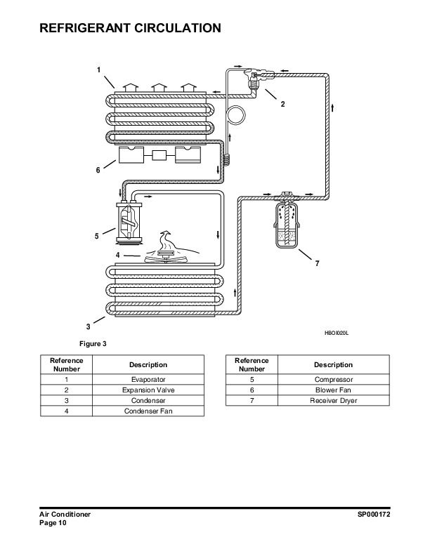
Refrigerant Circulation..273
Control Specifications..279
Temperature Level Control and Display..282
Air Discharge According to Path Selection..307
Face + Rear..491
Defroster + Rear..903
Airconditioning System Circuit Diagram..369
Refrigerant System Repairs..873
Refrigerant Safe Handling Procedures..882
Repair and Replacement Procedure..873
Leakage Check..372
Refrigerant Charging..373
Inspecting System for Leakage..515
Electrical SystemSP000268..948
Electrical Schematic (DL300)..1016
Safety Precautions..312
Applicable Models..1020
General Description..1022
DL300..1023


