Bobcat MT52, MT55 Mini Track Loader Factory Service & Shop Manual
Catalog:
Model:
Complete workshop repair service manual with electrical wiring diagrams for Bobcat MT52, MT55 Mini Track Loader. It's the same service manual used by dealers that guaranteed to be fully functional and intact without any missing page.
This Bobcat MT52, MT55 Mini Track Loader service & repair manual (including maintenance, overhaul, disassembling & assembling, adjustment, tune-up, operation, inspecting, diagnostic & troubleshooting…) is divided into different sections. Each section covers a specific component or system with detailed illustrations. A table of contents is placed at the beginning of each section. Pages are easily found by category, and each page is expandable for great detail. The printer-ready PDF documents work like a charm on all kinds of devices.
6902524 (10-04) - MT52 Operation & Maintenance Manual.pdf
6902525 (3-06) - MT52 Service Manual.pdf
6903371 (5-07) - MT55 Mini Loader Operation & Maintenance Manual.pdf
6903372 (5-07) - MT52, MT55 Service Manual.pdf
6903375 (5-07) - MT52 Mini Loader Operation & Maintenance Manual.pdf
6986856 (8-10) - MT52 Mini Loader Operation & Maintenance Manual.pdf
6986858 (3-10) - MT55 Mini Loader Operation & Maintenance Manual.pdf
6986859 (3-11) - MT52, MT55 Mini Track Loader Service Manual.pdf
6986859 (9-10) - MT52, MT55 Mini Track Loader Service Manual.pdf
EXCERPT:
CONTENTS
SAFETY & MAINTENANCE . . . 10-01
HYDRAULIC SYSTEM . . . . . . . 20-01
HYDROSTATIC SYSTEM . . . . 30-01
DRIVE SYSTEM . . . . . . . 40-01
MAINFRAME . . . . 50-01
ELECTRICAL SYSTEM & ANALYSIS . . . . . 60-01
ENGINE SERVICE . . . . . 70-01
SPECIFICATIONS . . . . . . . SPEC-01
ALPHABETICAL INDEX . . .INDEX-01
…
ENGINE INFORMATION (CONT’D)
Removal And Installation (Cont’d)
Figure 70-10-11
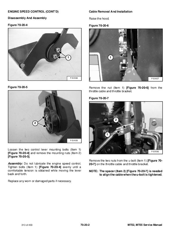
Remove the two side mounting bolts and nuts (Item 1) [Figure 70-10-11] from each side of the loader.
Figure 70-10-12
Remove the rear mounting bolt (Item 1) [Figure 70-10-12] from the loader.
Lift the engine out of the loader.
Reverse the removal procedure to install the engine.
Once the engine is placed back in the loader, check the drive belt alignment of the flywheel pulley, belt tensioner
and the hydrostatic pump pulleys. Adjustments can be made to align the drive belt properly. For more information on drive belt alignment: (See Alignment on Page 30-50-2.)
…


