Mercedes-Benz GL550 2006-2016 Workshop Repair & Service Manual
Catalog:
Model:
Complete repair workshop manual contains service, maintenance, and troubleshooting information for the 1998-2016 Mercedes-Benz GL-Class X164/X166 GL550. Diagnostic and repair procedures are covered in great detail to repair, maintain, rebuild, refurbish or restore your vehicle like a professional mechanic in local service/repair workshop. This cost-effective quality manual is 100% complete and intact as should be without any missing pages. It is the same factory shop manual used by dealers that guaranteed to be fully functional to save your precious time.
This manual for 1998-2016 Mercedes-Benz GL550 is divided into different sections. Each section covers a specific component or system and, in addition to the standard service procedures, includes disassembling, inspecting, and assembling instructions. A table of contents is placed at the beginning of each section. Pages are easily found by category, and each page is expandable for great detail. It is in the cross-platform PDF document format so that it works like a charm on all kinds of devices. You do not need to be skilled with a computer to use the manual.
EXCERPT:
TRANSMISSION Automatic Transmission - Basic Knowledge - 164 Chassis
BASIC KNOWLEDGE (-2008)
AUTOMATIC TRANSMISSION (AT), FUNCTION - GF27.10-P-0001GZ
TRANSMISSION 722.9 in MODEL 164.1
TRANSMISSION 722.9 in MODEL 164.8
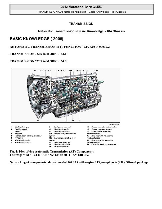
Fig. 1: Identifying Automatic Transmission (AT) Components
Networking of components, shown: model 164.175 with engine 113, except code (430) Offroad package
Fig. 2: Identifying Automatic Transmission (AT) Networking Of Components - Shown Model 164.175 With Engine 113
Transmission 722.9 is an electronically controlled automatic transmission with 7 forward gears and 2 reverse gears. All the transmission functions and transmission components for this automatic transmission are combined in one assembly module. Integrating the electrohydraulic controller unit in transmission 722.9 minimizes the number of interfaces to the wiring harness. The electrohydraulic controller unit is installed below the transmission housing; the transmission oil is continuously flushed around the outside of the controller unit, which amongst other things, ensures the controller unit is cooled.
Transmission 722.9 can be roughly divided into the following component groups:
Torque converter with torsional damper and torque converter lockup clutch.
Oil pump to produce the necessary oil pressure and for reliable lubrication of the actuators and bearing points.
Transmission housing with transmission mechanism and the electrohydraulic controller unit. The transmission housing is made of a light alloy.
The mechanical transmission components, consisting of a Ravigneaux gear set, front single planetary gear set, rear single planetary gear set and a park pawl. Additionally, a multi-disk clutch K1, multi-disk clutch K2, multi-disk clutch K3, multi-disk brake B1, multi-disk brake B2, multi-disk brake B3 and the BR multi-disk brake are also integrated. Single-sided disks are used on multidisk clutch K1, on multidisk clutch K2 and on multidisk clutch K3 Single-sided disks are also used on multidisk brake B1 and on
multidisk brake B3 On this type the friction lining is only applied on one side. Among other things, this improves heat distribution in the disk pack, the design of the disk pack is more compact, the load bearing capacity is increased and the mass is reduced. For the multi-disk brake B2 and BR multi-disk brake disks coated on both sides are also used.
Electrohydraulic controller unit consisting of the electric controller unit VGS (Y3/8), valve body and valve housing.
The following information are taken into account when shifting the drive positions:
Vehicle speed
Vehicle load
Driving resistance
Position and operating speed of accelerator pedal
Selected drive position and engaged gear
Selected transmission mode
Oil temperature and other information about the status of the transmission
Further signals which are available via the Controller Area Network bus class C (engine compartment) (CAN-C)
Data is exchanged with the following control units via CAN-C:
Instrument cluster
Intelligent servo module for DIRECT SELECT
CDI control unit (N3/9)
ME control unit
ESP control unit
Upper control panel control unit
EIS [EZS] control unit
Steering column module
Central gateway control unit
This involves the processing of the following data from other systems:
Intelligent servo module for DIRECT SELECT
Actual position of selection range lever CDI control unit (with engine 629, with engine 642)
Start-off in 1st gear, aids engine warm-up
Shift line displacement, aids engine warm-up
Shift line displacement, dependent on load condition of diesel particulate filter (DPF), a heavily loaded DPF results in slightly lower upshift speed for full-load and kick-down upshifts.
...


