Fendt 700, 800 Vario Repair Service Manual (X990.005.051.010)
Catalog:
Model:
Complete service repair manual with Electrical Wiring Diagrams for Fendt 700 Vario (711, 712, 714, 716), 800 Vario (815, 817, 818), with all the technical information to maintain, diagnose, repair, and rebuild like professional mechanics.
Fendt 700, 800 Vario workshop service repair manual includes:
* Numbered table of contents easy to use so that you can find the information you need fast.
* Detailed sub-steps expand on repair procedure information
* Numbered instructions guide you through every repair procedure step by step.
* Troubleshooting and electrical service procedures are combined with detailed wiring diagrams for ease of use.
* Notes, cautions and warnings throughout each chapter pinpoint critical information.
* Bold figure number help you quickly match illustrations with instructions.
* Detailed illustrations, drawings and photos guide you through every procedure.
* Enlarged inset helps you identify and examine parts in detail.
X990.005.051.010 Englisch 08_2006 - FENDT 700, 800 Vario Workshop Manual.pdf
PRODUCT DETAILS:
Total Pages: 1,246 pages
File Format: PDF (Internal Links, Bookmarked, Table of Contents, Searchable, Printable, high quality)
Language: English
711 Vario from chassis no. 711/../8001-, 712 Vario from chassis no. 712/../8001-, 714 Vario from chassis no. 714/../8001-, 716 Vario from chassis no. 716/../8001-
815 Vario from chassis no. 715/../1001-, 817 Vario from chassis no. 717/../1001-, 818 Vario from chassis no. 718/../1001-
TABLE OF CONTENTS
Book1...1
0000 - Tractor...2
A - General...2
Assembly overview...2
Documentation structure...6
Notes on documentation...8
Safety instructions and measures...9
Tightening torques for bolts in Nm...10
History of the Favorit 700 tractor range...11
Tractor diagnostics with terminal A008 (Variotronic Ti)...16
Technical specifications FENDT 700 Vario...20
Technical specifications FENDT 800 Vario...24
Fuels and lubricants...26
B - Faults...32
Confirming, calling up and deleting fault code...32
Vario Tractors - Fault Codes...34
Warning and fault messages...92
Fault messages Variotronic Ti...112
Troubleshooting chart for front suspension...116
Troubleshooting chart for the steering...118
General troubleshooting chart for the hydraulics...119
Troubleshooting chart: implement control block at Pext and LSext...121
Troubleshooting chart: implement control block on tractor valve...122
D - Component Location...123
Electrical / electronic components - A...123
Electrical / electronic components - B...127
Electrical / electronic components - E...136
Electrical / electronic components - G...139
Electrical / electronic components - H...140
Electrical / electronic components - K...141
Electrical / electronic components - M...142
Electrical / electronic components - R...144
Electrical / electronic components - S...145
Electrical / electronic components - V...154
Electrical / electronic components - X...155
Electrical / electronic components - Y...183
Hydraulic components...188
F - Setting and Calibration...208
General points on calibration...208
1. Calibration - rear EPC, code 8001 and 8002...209
2. Calibration - enhanced-control front power lift (where fitted), code 9001 and 9002...212
3. Calibration - hydraulic auxiliary control valves, code 1001...215
4. Calibration - suspension sensor, code 7666...220
5. Calibration - engagement point of rear PTO, code 6034...222
6. Calibration - engagement point of front PTO, code 7034...224
7. Calibration - clutch pedal sensor, code 4001...226
8. Calibration - hand throttle, code 4002...228
9. Calibration - operating range detection sensor, code 4003...230
10. Calibration - foot throttle sensor, code 4005...232
11. Calibration - transmission ratio characteristic curve, code 4007...234
12. Calibration - turboclutch operation, code 4009...239
13. Calibration - potentiometer 'accelerator pedal range' (sliding switch on the A034 - joystick), code 4010...241
1000 - Transmission...243
1000 - Transmission / General system...243
A - General...243
Description draft control...243
1005 - Transmission / transmission control unit...254
A - General...254
Transmission function schematic...254
Transmission programming...261
C - Documents and Diagrams...267
Transmission hydraulic system - Legend...267
E - Testing...274
Transmission pressure measurement...274
Measuring enhanced control system pressure...278
Checking clutch and turboclutch valve, and valve block...280
1010 - Transmission / Differential...283
C - Documents and Diagrams...283
Technical drawing - pinion shaft and ring gear...283
Technical drawing - differential gear assembly...285
G - Repair...286
Pinion shaft, diff. gears and ring gear - removing and installing...286
Removing and installing differential gear assembly...311
1015 - Transmission / axle drives...316
C - Documents and Diagrams...316
Technical drawing of axle drive...316
G - Repair...317
Installation and removal of axle drives...317
1030 - Transmission / Hand brake...319
F - Setting and Calibration...319
Setting hand brake...319
1070 - Transmission / brake system...322
A - General...322
General description of brake system...322
C - Documents and Diagrams...323
Technical drawing of brake cylinder...323
Technical drawing of rear brake...324
E - Testing...328
Setting master brake cylinder...328
Setting magnet for solenoid switch (S005 / S006)...330
F - Setting and Calibration...332
Adjusting rear wheel brake...332
G - Repair...334
Bleeding brake hydraulic system...334
Installation and removal of rear brake...337
Installing and removing brake cylinders...345
1080 - Transmission...351
A - General...351
2V3 / 2V4 high pressure relief valve forwards / reverse...351
G - Repair...353
Removing continuously variable drive...353
Installing the continuously variable transmission...364
Replacing high pressure relief valves forwards/reverse...376
Removing flush valve...377
Fill with transmission oil...378
1100 - Transmission / Clutch actuation system...380
E - Testing...380
Setting clutch master cylinder...380
G - Repair...383
Bleeding clutch hydraulics...383
1150 - Transmission / cardan-shaft brake...385
C - Documents and Diagrams...385
Technical drawing of cardan-shaft brake...385
E - Testing...386
Testing the cardan brake hydraulics...386
G - Repair...392
Repairing cardan-shaft brake...392
1200 - Transmission /Front PTO...399
A - General...399
Technical specifications of front PTO...399
C - Documents and Diagrams...401
Front PTO valve unit...401
Front PTO transmission...402
Front PTO drive (version without bush)...403
E - Testing...404
System pressure and clutch pressure...404
G - Repair...406
Installation and removal of front PTO clutch...406
Installation and removal of front PTO pump...423
Installation and removal of front PTO stub shaft...427
Fitting instructions Front p.t.o...430
1220 - Transmission / Live PTO...434
C - Documents and Diagrams...434
Technical drawing - Live PTO...434
Technical drawing - Hydraulic PTO shaft control...438
G - Repair...443
Live PTO clutch, installation / removal...443
Removing and installing live PTO speed preselection...462
1320 - Transmission / Front-wheel drive...484
G - Repair...484
Repairing front-wheel drive clutch...484
1430 - Transmission / Hydrodamp...495
G - Repair...495
Installation and removal of hydrodamp...495
1600 - Transmission / Enhanced actuation system valves...506
A - General...506
Operation of turboclutch pressure-relief valve (4V4)...506
Operation of clutch pressure-relief valve (4V5)...508
2000 - Engine...509
2000 - Engine / General system...509
A - General...509
Engine data FENDT 700 / 800 Vario...509
Determining engine power - comparison of standards and directives...516
Measuring PTO power...518
PTO power and fuel consumption...520
B - Faults...527
Troubleshooting flowchart EMR...527
EMR troubleshooting program...532
D - Component Location...580
Deutz 2013 engine series...580
Deutz 2013 engine series...582
2010 - Engine / Timing gear...585
A - General...585
Cylinder head...585
F - Setting and Calibration...588
Valve clearance setting...588
G - Repair...591
Replacing cylinder head gasket...591
2060 - Engine / Fuel system...594
C - Documents and Diagrams...594
Fuel system...594
E - Testing...604
Fuel system test instructions...604
2312 - Engine / Lubrication...607
D - Component Location...607
Lube oil circuit...607
E - Testing...610
Lubrication pressure test...610
2710 - Engine / Fuel injection pump...613
A - General...613
EMR 2 - General description...613
EMR 2 / TMS speed adjustment...622
F - Setting and Calibration...635
Idle hunting...635
G - Repair...637
Replacing fuel injection pump...637
2712 - Engine / Injectors...646
G - Repair...646
Removing and fitting injectors...646
2714 - Engine / Governor...650
G - Repair...650
Control rod stroke...650
3000 - Front axle...651
3020 - Front axle / Axle housing...651
G - Repair...651
Removing and fitting B047 - steering angle switch...651
3050 - Front axle / Suspension...653
A - General...653
Control system function charts...653
3180 - Front axle / Cardan shaft...658
G - Repair...658
Removing and fitting the cardan shaft...658
4000 - Steering...664
4000 - Steering / General system...664
A - General...664
Functional description...664
5000 - Vehicle body...667
5000 - Vehicle body / General system...667
A - General...667
Pneumatic cab suspension...667
5010 - Vehicle Construction / Body...670
G - Repair...670
Pneumatic cab suspension...670
5500 - Air-conditioning...673
5500 - Air-conditioning / General system...673
A - General...673
Function...673
Checking air-conditioning electrics...676
8100 - Cab...679
G - Repair...679
Tilting cab...679
Lowering cab...683
8610 - Power lift...686
8610 - Power lift / Electrohydraulic control EPC...686
A - General...686
EPC - OBE rear power lift...686
Operation and function of shock-load damping system...687
Operation and function of the slip control...690
B - Faults...695
Faults - electrics / electronic components EPC OBE...695
Troubleshooting table for power lift and service hydraulics (hydraulics)...701
Troubleshooting flowchart for rear power lift EPC-OBE...702
Faults in slip control (radar A011)...705
C - Documents and Diagrams...706
Sectional view and circuit diagram of EPC 23 - OBE...706
Rear power lift control system function charts...716
E - Testing...724
Slip control performance test...724
F - Setting and Calibration...730
Setting power lift end shutoff...730
G - Repair...731
Installation and removal of position sensor B030...731
8618 - Power lift/Electrohydraulic remote control...736
A - General...736
Operation and function of electrohydraulic remote control...736
Electrohydraulic remote control / terminal diagram...738
External position gauge - functional description...739
8631 - Power lift / Controlled power lift...741
C - Documents and Diagrams...741
Lifting cylinder 40 / 90, 247 / 458...741
Lifting cylinder 36 / 100, 247 / 458...743
Lifting cylinder 36 / 100, 247 / 507...745
8800 - Air compressor...747
8800 - Air compressor / General system...747
B - Faults...747
Troubleshooting flowchart, air compressor...747
C - Documents and Diagrams...754
Air compressor plan...754
D - Component Location...756
Position of components, air compressor...756
E - Testing...761
Overview of air compressors...761
Checking dual-line brake system in tractor...763
Checking single-line brake system in tractor...765
G - Repair...767
Mounting instructions for compressed air system...767
8820 - Air compressor / Brake fittings...784
F - Setting and Calibration...784
Setting pressure regulator (8.1 bar)...784
Trailer control valve (single-line)...785
Book2...787
9000 - Elektrik...788
9000 - Elektrik / Gesamtsystem...788
A - Allgemeines...788
Gerätekennzeichnung nach DIN 40719...788
Kennzeichnung von elektr. Leitungen und Tren...790
A013 - Sicherungsplatine, Teilzeichnung von X200...791
E - Testing...792
A002 - ECU, enhanced control...792
A004 - ECU, control console...808
A006 - front dashboard keypad...821
A007 - instrument cluster...823
A008 - terminal, operation of rotary potentiometers...827
A009 - actuator unit...828
A010 - electronic thermostat...832
A011 - radar sensor...834
A013 - Printed circuit board, fuse...837
A014 - ECU, EPC 23 OBE...840
A022 - ECU, EMR 2...855
A034 - joystick (CAN-BUS)...869
B002 - front PTO speed Hall sensor...873
B003 - suspension position sensor...874
B004 - underpressure switch...875
B008 - high pressure sensor...876
B009 - output temperature sensor...878
B010 - engine Hall sensor 1...880
B012 - engine oil pressure sensor...881
B013 - hydraulic oil thermostat...882
B014 - speed sensor for hydrostatic accumulator shaft...883
B015 - bevel pinion speed sensor...884
B016 - range position sensor...885
B017 - clutch pedal position sensor...886
B019 - compressed air volume pressure transducer...887
B020 - rear PTO speed Hall sensor...889
B021 - rear PTO speed Hall-effect sensor after clutch...890
B022 - sensor, kickout (NA version only)...891
B029 - foot throttle sensor (red)...893
B030 - sensor, rear power lift position...894
B031 / B032 - sensor, draft sensing pin (right / left)...896
B034 - fuel level sensor...898
B035 - Sensor, hand throttle...899
B038 - foot throttle sensor (EMR 2) (yellow)...900
B039 - high pressure sensor...901
B040 - front power lift position angular resolver...903
B041 - sensor, EMR (camshaft)...904
B042 - sensor, EMR (crankshaft)...906
B045 - sensor, air-conditioning 2 (anti-icing protection)...908
B046 - sensor, air-conditioning 1 (in air current)...909
B047 - steering angle switch...910
B048 - sensor, water temperature...912
B053 - sensor, charge air temperature/boost pressure...915
B055 - combi-sensor (voltage - current)...920
CAN - BUS...922
E015 / E016 / E017 / E018 - Work lights...924
G001 / G003 - battery...928
G002 / G004 - generator...930
Camera...931
M002 / M004 - front / rear wiper motor...934
M003 - wiper pump, front...936
M005 - wiper pump, rear...937
M007 - seat adjustment motor (compressor)...938
M008 - heater blower...939
M009 - blower...941
M014 - infinitely adjustable roof blower...944
R002 - heating flange / K034 - relay...945
S005 / S006 right / left brake solenoid switch...951
S012 - starter inhibitor switch...953
S013 - Emergency mode pushbutton...954
S015 - switch, hand brake...956
S017 - switch, filter clogging...957
S019 / S020 - left / right rear 'PTO on'switch...959
S021 - external switch, 'Raise' front power lift...961
S022 - external switch, 'Lower' front power lift...962
S024 - brake fluid indicator...963
S025 / S026 - pressure switch and flow controller...964
S027 - External right rear power lift 'Raise' button...966
S028 - External right rear power lift 'Lower' button...967
S029 - external left rear 'Raise' power lift switch...968
S030 - External left rear power lift 'Lower' button...969
S034 - coolant level switch...970
S035 - air-conditioning high/low pressure switch...971
S036 - hydraulic oil level sensor...972
S044 - switch, air-conditioning...973
S047 - switch, exhaust brake...975
S048 - 'EPC / DA switchover' solenoid switch...977
S053 - switch, driver seat...978
S061 - switch, rapid reversing...979
S067 - external valve actuation button 'raise'...981
S068 - external valve actuation button 'lower'...983
S069 - infinitely adjustable roof blower switch...985
X007 - Implement socket cable coupler...987
X008 - on-board computer counter input cable coupler (implement socket)...991
X1048 - ABS socket...992
Y003 - range 1 solenoid valve...994
Y003 - range 2 solenoid valve...996
Y004 - transmission neutral solenoid valve / turboclutch valve...998
Y005 - speed governor solenoid valve...1000
Y006 - exhaust brake solenoid valve...1001
Y008 / Y009 / Y010 - rear PTO / 4WD / diff. lock solenoid valve...1002
Y011 - front PTO solenoid valve...1003
Y012 - Suspension 'Load' solenoid valve...1004
Y013 - 'Lower' suspension solenoid valve...1006
Y014 - 'Raise' suspension solenoid valve...1008
Y015-Y019 - SB 23 - LS - EHS control valve...1010
Y023 - compressed air pilot control system solenoid valve...1012
Y024 - air-conditioning magnetic clutch...1013
Y026 / Y027 / Y028 - PTO 540 / 750 / 1000 solenoid valve...1014
Y032 - 'Control pressure valve' solenoid valve...1015
Y033 - valve, flushing (oil preheater)...1016
Y035 - Final control element, EMR 2...1019
Y053 - solenoid valve, active parking function...1025
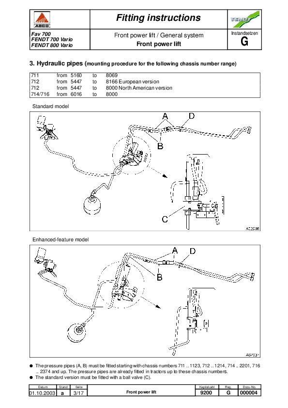
9200 - Front power lift...1027
G - Instandsetzen...1027
Front power lift...1027
9400 - Hydraulic pump assembly...1044
9420 - Hydraulic pump assembly / Transmission pump...1044
A - General...1044
Function of the LS pump (working and steering hydraulics)...1044
9430 - Hydr. pump installation / steering pump...1051
E - Testing...1051
PL - auxiliary pump...1051
9600 - Hydraulics...1054
9600 - Hydraulics / General system...1054
A - General...1054
Hydraulic system - hydraulic components...1054
Pressure control system - DR (axial-flow piston pump)...1062
22 bar control pressure...1065
C - Documents and Diagrams...1066
Hydraulic circuit diagram with key...1066
D - Component Location...1070
Pressure-measuring point overview...1070
E - Testing...1071
Test report - fax template...1071
9610 - Hydraulics / Central control block...1073
A - General...1073
Central control block...1073
9620 - Hydraulics / Valve assemblies...1076
A - General...1076
End plate (up to 09 / 2003)...1076
End plate (from 09 / 2003 onward)...1079
Control valves SB 23 LS - EHS / Emergency mode...1084
E - Testing...1090
Nitrogen diaphragm accumulator - STSP...1090
F - Setting and Calibration...1095
Setting valve number / Changing valve number...1095
G - Repair...1102
Fitting and removing SB 23 LS-EHS control valves...1102
Removing and fitting control pressure microfilter - FF...1110
Installation and removal of pilot valve...1118
Removing and fitting a shutoff valve...1123
9666 - Hydraulic systems / external pressure supply...1131
G - Repair...1131
Fitting instructions for external pressure supply...1131
9690 - Hydraulics / Valve supplement...1137
E - Testing...1137
Hydraulic oil preheater...1137
9700 - Electronics...1142
9700 - Electronics / General system...1142
A - General...1142
CAN-bus...1142
FENDT 700 / 800 Vario electronics concept...1144
Functional principle: Variotronic TI ('Teach In')...1146
Functional sensors and EST A002...1152
Function of diagnosis-capable sensors...1154
Electrical circuit diagram - Hall-effect sensor...1155
Electrical circuit diagram - switches/buttons/controls...1156
Electrical circuit diagram rotary position sensor...1157
9717 - Vehicle body / Bus system...1160
A - General...1160
ISO - BUS implement control...1160
ISO/LBS implement control...1163
9750 - Electronics / transmission actuator unit...1173
G - Repair...1173
New emergency control (dome) on old actuator...1173
9770 - Electronics / Control unit...1178
G - Repair...1178
Installation and removal of control module in A004 - control console...1178
9900 - Service...1186
9920 - Service / Special tools...1186
A - General...1186
Tilting mechanism...1186
Special tools for EMR injection system...1187
Special tools...1189
C - Documents and Diagrams...1196
Special tool - pinion shaft, ring gear, axle drive...1196
Box of Tools for Release of Plug Contacts on Electrical Line Couplings...1198
9970 - Service / FENDIAS...1214
A - General...1214
Serdia on FENDT tractors...1214
Valve diagnostics (Vendi) for Bosch EHS 23 LS valves with fault memory...1239
Fendt 700, 800 Vario Repair Service Manual (X990.005.051.010)


