CNH Case Steyr 9000-Series Tractors Factory Service & Shop Manual
Catalog:
Model:
Complete workshop repair & service manual with electrical wiring diagrams for CNH Case Steyr old 9000 Series Tractors. It's the same service manual used by dealers that guaranteed to be fully functional and intact without any missing page.
This CNH Case Steyr 9000-Series Tractors (9105, 9105a, 9115, 9115a, 9125, 9125a, 9145, 9145a, CS68, CS75, CS78, CS78a, CS86, CS86a, CS94, CS94a, CS100, CS110, CS120, CS130, CS150, M968, M975, M9078, M9078a, M9086, M9086a, M9094, M9094a, WD320, WD420) service & repair manual (including maintenance, overhaul, disassembling & assembling, adjustment, tune-up, operation, inspecting, diagnostic & troubleshooting…) is divided into different sections. Each section covers a specific component or system with detailed illustrations. A table of contents is placed at the beginning of each section. Pages are easily found by category, and each page is expandable for great detail. The printer-ready PDF documents work like a charm on all kinds of devices.
“7-96100”
Case Steyr M9078, M9086, M9094 Tractors Service - Training Manual
SVA 7-96101; 161 MB PDF
CASE / CNH / STEYR: 9105, 9115, 9125, 9145, CS68, CS75, CS78, CS78a, CS86, CS86a, CS94, CS94a, CS100, CS110, CS120, CS130, CS150, M968, M975, M9078, M9078a, M9086, M9086a, M9094, M9094a, WD320, WD420
“7-96211”
CNH Österreich 9105, 9115, 9125, 9145 Tractors Service - Training Manual
SVA 7-96212; 233 MB PDF
CASE / CNH / STEYR: 9105, 9105a, 9115, 9115a, 9125, 9125a, 9145, 9145a, CS68, CS75, CS78, CS86, CS94, CS100, CS110, CS120, CS130, CS150
EXCERPT:
2. FLYWHEEL CASING
A. Fitting the flywheel casing
The flywheel casing is centered on the cylinder block by means of two sprung dowel pins. The flywheel casings, which are also available as a spare part, are supplied with the bore holes for the pins.
1. Clean the sealing surfaces between the cylinder block and flywheel housing.
2. Apply sealant (e.g. silicone) to the points shown in the figure.
3. Lift the flywheel casing to the correct position and insert all the bolts.
4. Centre the casing and fit the sprung dowel pins using a mandrel.
5. Tighten the inner ring bolts to a torque of 60 Nm and the outer ring bolts to a torque of 110 Nm.
B. Replacing the rear crankshaft sealing ring
1. Separate the tractor between the engine and power unit.
2. Remove the flywheel.
3. Remove the sealing ring without damaging the crankshaft.
4. Clean the sealing ring seat and grind any burr.
NOTE: If the crankshaft is worn at the sealing ring seat, a 2 mm spacer ring (spare part number 162000020718 can be fitted behind the crankshaft sealing ring.
5. Carefully press the sealing ring in down to the bottom of the flywheel casing using the 1TSW 521 and 1TSW 662 fitting tools.
NOTE: THE ASSEMBLY PROCEDURE MUST BE CARRIED OUT IN A DRY AND OIL-FREE STATE.
01_General
02_Engine
03_Fuel_system
04_Electrical_system
05_Steering_system
06_Transmission
08_Hydraulic_system
7-96100...2
02_engine...3
7-69860ge_en...4
7-98510en...78
INDEX...79
SPECIAL TOOLS...82
FOR THE USER...84
Engine serial number...84
SAFETY REGULATIONS...85
ENGINE DATA...86
Lifting the engine...86
TECHNICAL DATA...87
Cylinder block...87
Cylinder liners...87
Cylinder head...87
Valves, rocker arms and push rods...88
Camshaft...89
Crankshaft...89
Flywheel...90
crankshaft inertia weight (engine type 420)...90
Camshaft drive...90
Con-rods...91
Pistons, piston rings and piston pins...91
Lubrication system...92
Lubrication oil pump (320, 420)...92
Lubrication oil pump (620)...92
Thermostat...92
Coolant temperature switch Coolant temperature transmitter...92
Cooling water pump (320, 420)...93
Cooling water pump (620)...93
Turbo charger...93
Tightening torques...94
CONSTRUCTION...95
General information...95
Cylinder block...95
Flywheel casing...95
Cylinder head...96
Valve mechanism...96
Crankshaft drive...96
Timing gears...97
Lubrication system...98
Cooling system...99
Intake / exhaust system...100
JOB INSTRUCTIONS...101
1. CYLINDER BLOCK...101
A. Measuring the cylinder liner wear...101
B. Removing the cylinder liner...101
C. Checking the cylinder block...101
D. Replacing the camshaft bush...101
E. Oversize bushes for the camshaft...102
F. Fitting the plug at the rear camshaft end...104
G. Fitting the plug at the rear camshaft end after inserting an oversize bush...104
H. Installing the oil dipstick tube...104
I. Fitting the cylinder liner...104
2. FLYWHEEL CASING...106
A. Fitting the flywheel casing...106
B. Replacing the rear crankshaft sealing ring...106
3. CYLINDER HEAD...107
A. Removing the cylinder head...107
B. Removing the valves...107
C. Checking the cylinder head...107
D. Replacing the valve guides...108
E. Machining the valve seat...109
F. Replacing the valve seat rings...109
G. Grinding the valves...109
H. Fitting the valves...109
I. Fitting the cylinder head...110
4. VALVE MECHANISM...111
A. Maintenance of the rocker arm system...111
B. Replacing the camshaft / camshaft gear wheel...111
C. Checking and adjusting the valve clearance...112
5. CRANKSHAFT...113
A. Removing the crankshaft...113
B. Checking the crankshaft...113
C. Replacing the crankshaft gear wheels...113
D. Replacement of the crankshaft ring gear (engine type 420 only)...114
E. Fitting the crankshaft...114
F. Crankshaft hub...115
G. Replacing the crankshaft belt pulley and vibration damper...115
H. Checking the rubber element in the vibration damper (620/420)...116
6. CON-RODS AND PISTONS...117
A. Removing the pistons together with the con-rods...117
B. Checking and replacing the con-rod bearings...117
C. Checking the con-rod...117
D. Con-rod weight groups...118
E. Checking and replacing the piston rings...119
F. Checking the pistons...120
G. Fitting the piston pin...120
H. Fitting the pistons and con-rods...120
7. BALANCING UNIT (420)...121
A. Removing and dismantling the balancing unit...121
B. Balancing unit maintenance...121
C. Fitting the balancing unit...121
8. FLYWHEEL...122
A. Replacing the starter ring gear on the flywheel...122
B. Fitting the flywheel...122
9. TIMING MECHANISM...123
A. Removing the timing gear case...123
B. Replacing the intermediate gear wheel bush...123
C. Fitting the timing gear case...124
D. Front power take-off / auxiliary drive...125
10. LUBRICATION SYSTEM...126
A. Checking the oil pressure valve...126
B. Removing and checking the oil pump...126
C. Assembling and fitting the oil pump...127
D. Fitting the sump...127
E. Oil cooler...127
F. Piston cooling nozzles (620)...128
G. Recommended lubrication oils...128
11. COOLING SYSTEM...129
A. Thermostat...129
B. Repairing the coolant pump...129
C. Coolant quality requirements...130
12. INTAKE / EXHAUST SYSTEM...131
A. Checking the air filter...131
B. Checking the intake / exhaust system...131
C. Checking the boost pressure...131
D. Checking the turbo charger...132
E. Fitting the turbo charger...133
03_fuel_system...134
7-97340...135
04_electrical_system...155
7-95391en...156
SPECIAL TOOLS...158
TROUBLESHOOTING USING THE DIAGNOSTIC SYSTEM...162
Plug...163
X9/1...163
Plug...164
X9/2...164
Plug...165
X9/3...165
Plug...166
X9/4...166
Plug...167
X9/5...167
Plug...168
X9/5...168
Plug...169
X9/5...169
Plug...170
X9/6...170
Plug...171
X9/6...171
TEST VALUES...172
1. Frequency to check display of rear PTO shaft speed:...172
2. Frequencies of speed signal of rear PTO shaft:...172
3. Frequency to check front PTO shaft speed signal:...172
4. Frequency to check analogue speed display:...172
5. Fuel gauge:...173
6. Engine temperature gauge:...173
7. Coolant temperature switch S32...173
8. Compressed air indicator:...173
OPERATING AND CODING OF THE DIGITAL INSTRUMENT WITH INTEGRATED OPERATING HOURS COUNTER...174
CALIBRATING THE DRIVING SPEED...175
7-96680EN...176
Index for Circuit Diagram...179
LIST OF PLUGS, LEFT...269
LIST OF PLUGS, RIGHT...270
LIST OF PLUGS, REAR...271
LIST OF PLUGS, INSTRUMENT PANEL...272
LIST OF PLUGS, RIGHT-HAND SIDE PANEL...273
LIST OF PLUGS, LEFT-HAND SIDE PANEL...274
CENTRAL PRINT A12...275
ROOF PRINT A13...277
COMPONENT CARRIER, LOW-TOP...279
COMPONENT CARRIER, ENGINE ELECTRICS...280
EHR-D PRINT, LEFT, A15...281
EHR CONTROL CONSOLE PRINT A16...281
MHR CONTROL CONSOLE PRINT A16...282
EHR OPERATION A51...282
EHR-D BOX A55...283
POWER SHIFT 'E' Box A52...283
'E' BOX MULTI – JOYSTICK A11/1...284
E-BOX, REAR PTO SHAFT A50/2...284
PRINT, SINGLE WINCH A33/1 (PRINT, DOUBLE WINCH A33/2)...285
EGE CONTROL UNIT A10...285
AIR CONDITIONING THERMOSTAT SWITCH...286
BLOWER MOTOR CONTROL A21...286
AIR CONDITIONING CONTROL A20...286
RELAYS...287
Miniature relay: (Messr's. Wehrle)...287
Miniature relay:...287
Power relay: (Messr's. Wehrle)...287
Changeover – micro-relay: (Siemens)...287
Changeover – micro-relay: (Messrs Wehrle, Siemens)...288
Changeover – micro-relay: (Bosch)...288
Timed relay 40 sec's. K4/2/2: (Messr's Wehrle u. Sohn)...288
Time relays, 3 sec., K4/1/1, K4/1/2:...288
Control unit 14km/h A9:...288
SWITCHES...289
Engine oil pressure switch (S6):...289
Switch, cooling water temperature (S32):...289
Start safety switch (S10):...289
Pressure switches:...289
Front PTO shaft (S29)...289
Power shift safety switch (S9):...289
Safety switch – Air-cond. system (S30):...289
Compressed air switch (S12):...290
Reed switches (S40/2,S42,S43):...290
Reed – changeover relay (S41/1,S41/2):...290
Stop solenoid (Y12):...290
Glow plug (E10/1):...290
Fuel pre-heating thermostatic switch:...290
POTENTIOMETERS...291
Air-cond. roof blower motor potentiometer (R11):...291
Air-cond. potentiometer (R10):...291
EHR potentiometer (R6/1,R6/2,R6/3,R6/4):...291
Stepping potentiometer EGE (R8):...291
SENSORS...292
EHR position sensor (B9/1):...292
EHR force measuring bolts (B10/1,B10/2):...292
Inductive transmitter, driving speed (B6),...292
Rear PTO shaft speed (B7):...292
Air-conditioning temperature sensor (R9):...292
Pressure sensor EGE M2 (B20):...292
SOLENOID VALVES...293
Solenoid valve 4-wheel drive (Y1) Power shift (Y3) Rear axle diff. lock (Y10) Front axle differen...293
Solenoid valve EHR control unit (Y6,Y7):...293
Solenoid valve (shut-off valve) Auxiliary control unit (Y2/4):...293
Solenoid valve (directional control valve) Auxiliary control unit (Y2/1,Y2/2,Y2/3):...293
Solenoid valve EGE (Y2/1, Y2/2):...293
(Messr's. Wandfluh)...293
Solenoid valve EGE (Y20, Y21):...293
INSTRUMENT TEST VALUES...294
LAMPS AND FUSES...295
OPERATING AND CODING OF THE DIGITAL INSTRUMENT WITH INTEGRATED OPERATING HOURS COUNTER...296
General information...296
Operating / function...296
Coding...296
General information...296
Coding the engine speed indication (operating hours)...296
Coding the rear PTO shaft speed indication...296
Coding the rear PTO front speed indication...296
CALIBRATING THE DRIVING SPEED...297
7-97390en...298
7-98691EN...416
Index for Circuit Diagram...419
M9078 - M9094 CS78 - CS94...419
List of Plugs, Left...497
List of Plugs, Right...498
List of Plugs (at rear)...499
List of Plugs – Instrument Panel...500
List of plugs, roof lining, high-top...501
List of plugs, roof lining, low-top...501
List of plugs, EHR, right-hand side panel...502
List of plugs, EHR, right-hand side panel, with EGE and EFH...503
List of plugs, MHR, right-hand side panel, with EGE and EFH...504
List of Plugs – Left-hand Side Panel...505
Central Print A12...506
ECCU A60 (Electronic Central Control Unit)...508
Print – Roof electrics A13...509
Component carrier – Low-Top...511
Component Carrier – Engine Electrics...512
Print – EHR Left, A15 (Distribution Print)...513
Print, EHR-B Operating Console A16...513
MHR – Operating Console A16...514
EHR Control Unit A25...514
EGE Control Unit A11...515
EFH print A17...515
EFH control unit A55/2...516
4-Wheel Drive Management – Control Unit A10...516
Blower motor – Control A21...517
Air-Conditioning – Control A20...517
Relays...518
Switch...519
Potentiometer for...521
Sensors...522
Solenoid Valves...524
Heating elements...526
Instrument Test Values...527
Lamps and Fuses...528
Operation and Coding the Digital Instrument with Integrated operating HoursCounter...529
Calibrating the speedometer...530
Page 37...493
Page 38...495
7-99220 EN...532
TABLE OF CONTENTS...533
GENERAL INFORMATION...534
ELECTRICAL FITTINGS...535
OPERATING INSTRUCTIONS SAFETY DEVICES AND PROTECTIVE MEASURES...536
ECCU – POWER SUPPLY...537
POWER SHIFT POWER 2 – FUNCTION...538
EHR CONTROL 'TRANSPORT'...539
EHR CONTROL 'CONTROL' (LOWER)...540
EHR CONTROL 'FAST RETRACT'...541
REAR PTO SHAFT: FUNCTION...542
REAR PTO SHAFT: SWITCHING ON AND OFF...543
REAR PTO SHAFT: MANAGEMENT...544
AUXILIARY CONTROL UNIT – PRESSURE IN CONNECTION 'A' (WITH MULTI-CONTROLLER)...545
AUXILIARY CONTROL UNIT – PRESSURE IN CONNECTION 'B' (WITH MULTI-CONTROLLER)...546
AUXILIARY CONTROL UNIT – 'FREEDOM OF MOVEMENT OR FLOATING POSITION' (WITH MULTI-CONTROLLER)...547
AUXILIARY CONTROL UNIT – PRESSURE IN CONNECTION 'A' (WITH LEVER SWITCH)...548
AUXILIARY CONTROL UNIT – PRESSURE IN CONNECTION 'B' (WITH LEVER SWITCH)...549
AUXILIARY CONTROL UNIT – 'FREEDOM OF MOVEMENT OR FLOATING POSITION' (WITH LEVER SWITCH)...550
4-WHEEL DRIVE (MFD) 'ON' (WITHOUT MANAGEMENT AND OPTISTOP)...551
4-WHEEL DRIVE (MFD) 'OFF' (WITHOUT MANAGEMENT AND OPTISTOP)...552
4-WHEEL DRIVE (MFD) 'ON' (WITH MANAGEMENT AND OPTISTOP)...553
4-WHEEL DRIVE (MFD) 'OFF' (WITH MANAGEMENT AND OPTISTOP)...553
DIFFERENTIAL LOCK(S) – MANAGEMENT – EHR IN 'CONTROL' FUNCTION...554
DIFFERENTIAL LOCK(S) – MANAGEMENT – EHR IN 'TRANSPORT' FUNCTION...554
05_steering_system...556
7-70620ge_en...557
06_transmission...595
7-97150...596
7-99240en...602
08_hydraulic_system...750
6-50640en...751
FUNCTIONAL DESCRIPTION AND TROUBLESHOOTING...751
Electronic front hitch control (EFH) M9078, M9086, M9094 CS78, CS86, CS94 from DBD0057987 onwards...751
ELECTRONIC FRONT HITCH CONTROL (EFH)...753
Functions...753
Type of control...753
General Remarks...753
COMPONENTS...754
4...754
GENERAL DESCRIPTION...755
OPERATING CONTROLS...756
1. Multi-Controller...757
1...757
2. Indicator lamp IMPLEMENT LOAD RELIEF (green)...757
2...757
3. Indicator lamp DIAGNOSIS (red)...757
3...757
4. RAISE / TRANSPORT button...758
4...758
5. LOWER / CONTROL button...758
5...758
6. Setpoint stepping switch...759
7. Potentiometer for mixed control...760
8. Potentiometer for lift limitation...761
9. Potentiometer for lowering speed...762
10. RAISE / LOWER button (in the cab)...763
10...763
11. Front operation...763
1...763
12. Changeover switch (latchable) for RAISE/AUTO (Automatic) operatingmode...763
12...763
13. Safety switch (latchable)...764
13...764
POSITION CONTROL FUNCTION...765
4...765
PRESSURE CONTROL FUNCTION...766
4...766
CALIBRATION...767
OSCILLATION DAMPING...768
EMERGENCY OPERATION...769
2...769
POSITION SENSOR...770
Construction and function...770
Characteristic curve...771
Technical Data...771
Adjusting the Position Sensor...772
PRESSURE SENSOR...773
Function:...773
Technical Data...774
RESERVOIR BLOCK (complete)...775
3...775
EFH LINE PLAN – EHR version...776
EFH LINE PLAN – MHR version...778
EFH CONTROL VALVE SB 23-OC...780
4...780
Technical data:...780
NEUTRAL function...781
4...781
RAISE function...782
2...782
LOWER function...783
3...783
EFH CONTROL VALVE SB 23-LS...784
3...784
NEUTRAL function...784
RAISE function...785
10...785
LOWER function...786
7...786
DIAGNOSIS...787
General...787
Fault code display...787
Fault code assignment...787
Minor faults...787
Fairly serious faults...787
Serious faults...787
Remedying of faults...787
Fault codes...788
MINOR FAULTS...788
FAIRLY SERIOUS FAULTS...789
SERIOUS FAULTS...790
Pin assignment, plug X55 (EFH box A55/2)...791
Plug X55...792
TROUBLESHOOTING USING THE DIAGNOSTIC SYSTEM...793
General...793
Test conditions...793
Measuring procedure (example)...793
Parts of the diagnostic system required...793
LOAD RELIEF signal...796
7-95350en...801
7-99420EN...895
EHR-B ELECTRONIC LIFTING GEAR CONTROL SYSTEM...899
Functions of the EHR-B...899
General Remarks...899
EHR-B COMPONENTS...900
EHR-B OPERATION...901
FUNCTIONAL DESCRIPTION (WITHOUT MULTI-CONTROLLER)...902
1. Raise switch (without multi-controller):...903
FUNCTIONAL DESCRIPTION (WITH MULTI-CONTROLLER)...904
1. Buttons for Transport and Control on the Multi-Controller:...905
2. Setpoint adjusting wheel:...906
3. Pulling power control:...907
4. Lift Limiting:...908
5. Lowering speed:...909
BASIC FUNCTIONS OF THE EHR FOR POSITION CONTROL...910
BASIC FUNCTIONS OF THE EHR FOR PULLING POWER CONTROL...911
OSCILLATION DAMPING...912
Deactivating oscillation damping...914
6. Light emitting diodes:...914
7. Stop button:...914
8. Safety switch:...914
9. Traction control indicator lamp:...915
10. Diagnosis display:...915
11. Rear operating position:...915
EMERGENCY OPERATION...916
DIGITAL, INDUCTIVE POSITION SENSOR...917
Position sensor – Technical Data and Characteristics...918
Adjusting the Position Sensor...919
POWER SENSORS – DESIGN AND INSTALLATION...920
Power Sensor – Technical Data and Signal Shaping...921
ELECTRONIC CONTROL UNIT (with management functions)...922
HIGH PRESSURE HYDRAULIC CIRCUIT...924
CONTROL VALVE EHR 5-OC...926
NEUTRAL FUNCTION – GRAPHIC 2...928
RAISE FUNCTION – GRAPHIC 3...930
LOWER FUNCTION – GRAPHIC 5 AND GRAPHIC 6...932
EHR-B DIAGNOSIS...934
FAULT CODE LIST...935
SERIOUS FAULTS...935
MEDIUM FAULTS...935
SLIGHT FAULTS...936
PIN ASSIGNMENT OF EHR-B BOX A25...937
TROUBLESHOOTING USING THE DIAGNOSTIC SYSTEM...938
7-96111EN...945
7-96211...946
02_engine...947
7-70670...948
7-98510en...1045
INDEX...1046
SPECIAL TOOLS...1049
FOR THE USER...1051
Engine serial number...1051
SAFETY REGULATIONS...1052
ENGINE DATA...1053
Lifting the engine...1053
TECHNICAL DATA...1054
Cylinder block...1054
Cylinder liners...1054
Cylinder head...1054
Valves, rocker arms and push rods...1055
Camshaft...1056
Crankshaft...1056
Flywheel...1057
crankshaft inertia weight (engine type 420)...1057
Camshaft drive...1057
Con-rods...1058
Pistons, piston rings and piston pins...1058
Lubrication system...1059
Lubrication oil pump (320, 420)...1059
Lubrication oil pump (620)...1059
Thermostat...1059
Coolant temperature switch Coolant temperature transmitter...1059
Cooling water pump (320, 420)...1060
Cooling water pump (620)...1060
Turbo charger...1060
Tightening torques...1061
CONSTRUCTION...1062
General information...1062
Cylinder block...1062
Flywheel casing...1062
Cylinder head...1063
Valve mechanism...1063
Crankshaft drive...1063
Timing gears...1064
Lubrication system...1065
Cooling system...1066
Intake / exhaust system...1067
JOB INSTRUCTIONS...1068
1. CYLINDER BLOCK...1068
A. Measuring the cylinder liner wear...1068
B. Removing the cylinder liner...1068
C. Checking the cylinder block...1068
D. Replacing the camshaft bush...1068
E. Oversize bushes for the camshaft...1069
F. Fitting the plug at the rear camshaft end...1071
G. Fitting the plug at the rear camshaft end after inserting an oversize bush...1071
H. Installing the oil dipstick tube...1071
I. Fitting the cylinder liner...1071
2. FLYWHEEL CASING...1073
A. Fitting the flywheel casing...1073
B. Replacing the rear crankshaft sealing ring...1073
3. CYLINDER HEAD...1074
A. Removing the cylinder head...1074
B. Removing the valves...1074
C. Checking the cylinder head...1074
D. Replacing the valve guides...1075
E. Machining the valve seat...1076
F. Replacing the valve seat rings...1076
G. Grinding the valves...1076
H. Fitting the valves...1076
I. Fitting the cylinder head...1077
4. VALVE MECHANISM...1078
A. Maintenance of the rocker arm system...1078
B. Replacing the camshaft / camshaft gear wheel...1078
C. Checking and adjusting the valve clearance...1079
5. CRANKSHAFT...1080
A. Removing the crankshaft...1080
B. Checking the crankshaft...1080
C. Replacing the crankshaft gear wheels...1080
D. Replacement of the crankshaft ring gear (engine type 420 only)...1081
E. Fitting the crankshaft...1081
F. Crankshaft hub...1082
G. Replacing the crankshaft belt pulley and vibration damper...1082
H. Checking the rubber element in the vibration damper (620/420)...1083
6. CON-RODS AND PISTONS...1084
A. Removing the pistons together with the con-rods...1084
B. Checking and replacing the con-rod bearings...1084
C. Checking the con-rod...1084
D. Con-rod weight groups...1085
E. Checking and replacing the piston rings...1086
F. Checking the pistons...1087
G. Fitting the piston pin...1087
H. Fitting the pistons and con-rods...1087
7. BALANCING UNIT (420)...1088
A. Removing and dismantling the balancing unit...1088
B. Balancing unit maintenance...1088
C. Fitting the balancing unit...1088
8. FLYWHEEL...1089
A. Replacing the starter ring gear on the flywheel...1089
B. Fitting the flywheel...1089
9. TIMING MECHANISM...1090
A. Removing the timing gear case...1090
B. Replacing the intermediate gear wheel bush...1090
C. Fitting the timing gear case...1091
D. Front power take-off / auxiliary drive...1092
10. LUBRICATION SYSTEM...1093
A. Checking the oil pressure valve...1093
B. Removing and checking the oil pump...1093
C. Assembling and fitting the oil pump...1094
D. Fitting the sump...1094
E. Oil cooler...1094
F. Piston cooling nozzles (620)...1095
G. Recommended lubrication oils...1095
11. COOLING SYSTEM...1096
A. Thermostat...1096
B. Repairing the coolant pump...1096
C. Coolant quality requirements...1097
12. INTAKE / EXHAUST SYSTEM...1098
A. Checking the air filter...1098
B. Checking the intake / exhaust system...1098
C. Checking the boost pressure...1098
D. Checking the turbo charger...1099
E. Fitting the turbo charger...1100
03_fuel_system...1101
7-96660EN...1102
SPECIAL TOOLS...1104
GENERAL INFORMATION...1105
TECHNICAL DATA...1106
Bosch injection pump...1106
Oil fill quantity (when fitting injection pump)...1106
Pump type...1106
Injection sequence...1106
Idling speed...1106
Cut-out solenoid...1106
Starting-fuel solenoid Y16 (420.80 only)...1106
Fuel pump...1106
Stanadyne injection nozzles...1106
Thermo-start unit...1106
Tightening torques...1106
Removal of the injection nozzle mounting...1107
Checking the injection nozzles...1107
Overhauling the injection nozzles...1108
Fitting the injection nozzle mounting into the cylinder head...1108
Assembly of the injection lines...1108
Removal of the injection pump...1112
Installation of the injection pump...1112
Checking start of delivery...1112
Readjustment of start of delivery...1113
B. Installation when gear wheels are fastened without spline...1113
Bleeding the fuel system of air...1114
Thermo-start system...1115
Bleeding the thermo-start system of air...1115
Measuring the fuel feed pressure...1115
Checking the overflow valve...1115
Checking the fuel delivery pump...1116
Replacing the fuel delivery pump valves...1116
Adjusting the minimum idling speed...1116
Fuel quality requirements...1117
Bio-diesel fuel...1117
INJECTION NOZZLE MOUNTING...1107
INJECTION PUMP...1109
7-99110en...1118
SPECIAL TOOLS...1121
GENERAL INFORMATION...1122
TECHNICAL DATA...1123
Stanadyne injection pump...1123
Pump type...1123
Injection sequence...1123
Cut-out solenoid...1123
Fuel pump...1123
Stanadyne injection nozzles...1123
Thermo-start unit...1123
Tightening torques...1123
FUEL SYSTEM WITH STANADYNE DISTRIBUTOR INJECTION PUMP...1124
Injection nozzles...1125
Removing the injection nozzles...1125
Checking the injection nozzles...1125
Overhauling the injection nozzles...1126
Assembly of the injection nozzles in the cylinder head...1126
Assembly of the injection lines...1126
Stanadyne distributor injection pump...1127
Construction of the Stanadyne distributor injection pump...1128
How the Stanadyne distributor injection pump works...1129
Removal of the injection pump...1130
Assembly of the injection pump and adjustment of the delivery start (static)...1130
Bleeding the fuel system...1131
Thermo-start system...1131
Bleeding the thermo-start system...1131
Adjusting the idling speed...1132
Measuring the fuel feed pressure...1132
Testing the fuel pressure...1132
Checking the delivery start using TIME TRAC (dynamic)...1133
TIME TRAC setting and check values...1134
Troubleshooting when using the TIME TRAC...1134
Fuel quality requirements...1135
Bio-diesel fuel...1135
04_electrical_system...1136
6-50950en...1137
Index for Circuit Diagram...1140
List of plugs, left...1228
List of plugs, right...1229
List of plugs (at rear)...1230
List of plugs on instrument carrier...1231
List of plugs on the right-hand side of the cab...1232
Central Electrics Print A12...1233
Print – Roof electrics A13...1236
Print A14, engine electrics...1238
Print – EHR Left, A15 (Distribution Print)...1240
EHR-D Print, operating console, A16...1240
Print, single/double winch A33/1 and A33/2...1241
Instrument carrier for low-top version...1242
Relays...1243
Components, gearbox electrics / electronics...1244
Components, electronic 3-point hitch control...1247
Components, air conditioning system...1249
Components, engine / fuel system...1251
Components, sprung front axle...1252
Components, hydraulics...1253
Components, brake...1254
Components, cab...1255
ECCU – Electronic Central Control Unit...1256
Test Values...1257
Lamps and Fuses...1258
Operation and coding of the digital instrument with integrated operating hours counter...1259
Calibrating the ”Driving speed” display...1260
7-70640...1261
7-95830...1379
Index for Circuit diagram...1382
Sheet 1...1384
Sheet 2...1386
Sheet 3...1388
Sheet 4...1390
Sheet 5...1392
Sheet 6...1394
Sheet 7...1396
Sheet 8...1398
Sheet 9...1400
Sheet 10...1402
Sheet 11...1404
Sheet 12...1406
Sheet 13...1408
Sheet 14...1410
Sheet 15...1412
Sheet 16...1414
Sheet 17...1416
Sheet 18...1418
Sheet 19...1420
Sheet 20...1422
Sheet 21...1424
Sheet 22...1426
Sheet 23...1428
Sheet 24...1430
Sheet 25...1432
Sheet 26...1434
Sheet 27...1436
Sheet 28...1438
Sheet 29...1440
Sheet 30...1442
Sheet 31...1444
Sheet 32...1446
Sheet 33...1448
Sheet 34...1450
Sheet 35...1452
Sheet 36...1454
Sheet 37...1456
Sheet 38...1458
List of Plugs...1460
List of Plugs...1461
List of Plugs (at rear)...1462
List of Plugs – Instrument Panel...1463
List of Plugs – Right-hand Side Panel...1464
Central Electrics Print...1465
Central Electrics Print...1466
Print – Roof electrics...1468
Engine Electrics Print...1470
EHR-D Print (left)...1472
EHR-D Print (operating console)...1473
Single Winch Print...1474
Relays...1475
Switches...1476
Potentiometers...1478
Sensors...1479
Solenoid Valves...1481
ECCU – Electronic Central Control Unit...1483
Instrument Test Values...1484
Lamps and Fuses...1485
Operation and Coding the Digital Instrument with Integrated operatingHours Counter...1486
Calibrating the speedometer...1487
7-97221en...1489
05_steering_system...1515
7-71500...1516
7-97101en...1556
GENERAL DESCRIPTION...1559
COMPONENTS...1560
OPERATION...1561
Main Switch, Suspension ON / OFF...1561
Auxiliary switch (pushbutton function only, pressed to the left – lower, to the right – raise)...1561
Indicator lamp on the instrument panel...1561
FUNCTION OF THE SUSPENSION...1562
Calibration procedure...1562
Control Function...1563
AXLE SENSORS...1564
General Remarks...1564
Testing the 'Sensor Settings'...1565
Adjusting the Sensors...1567
LOWERING THE FRONT AXLE MANUALLY...1568
ERROR CODES...1569
TROUBLESHOOTING USING THE DIAGNOSTIC SYSTEM...1570
Measurement table...1571
Test – solenoid valve control...1573
Circuit Diagram, Sprung Front Axle...1574
SPECIAL TOOLS...1558
7-98580en...1576
TABLE OF CONTENTS...1577
TECHNICAL DATA...1578
SPECIAL TIGHTENING TORQUES...1578
SPECIAL TOOLS...1579
GENERAL NOTES...1580
PLANETARY DRIVE...1580
Removing and Fitting...1580
Disassembly/Re-assembly...1581
WHEEL HUB...1582
Disassembly/Re-assembly...1582
Sectional drawing through the planetary gear and wheel hub...1584
PIVOT BEARING HOUSING...1585
Removing and Fitting...1585
Disassembly/Re-assembly...1586
KING PIN HOUSING...1587
Removing and Fitting...1587
Disassembly...1591
Assembly...1593
Sectional drawing, through the pivot bearing housing and thekingpinhousing...1595
DRIVE SHAFTS...1596
Disassembly/Re-assembly...1596
4-WHEEL DRIVE AXLE...1597
Removing and Fitting...1597
PIVOTED BEARING...1600
Disassembly/Re-assembly...1600
Disassembly...1601
Assembly...1603
Adjusting the Torsion Bars...1607
AXLE HOUSING...1610
Disassembly...1610
DIFFERENTIAL UNIT...1615
Disassembly...1615
Assembly...1615
Adjusting the Pinion Shaft...1617
Pinion Shaft Unit...1619
Fitting the Differential Unit...1621
Adjusting the Crown Wheel Tooth Flank Play...1623
Adjusting the Differential Bearing Pre-Tension...1624
TRACK ALIGNMENT...1626
06_transmission...1628
7-71450...1629
Index...2232
Special Tools, Category 1...2232
Disassembly...2233
Re-assembly...2237
Power shuttle – driving clutch...2237
Pre-assembling the inner disk carrier...2237
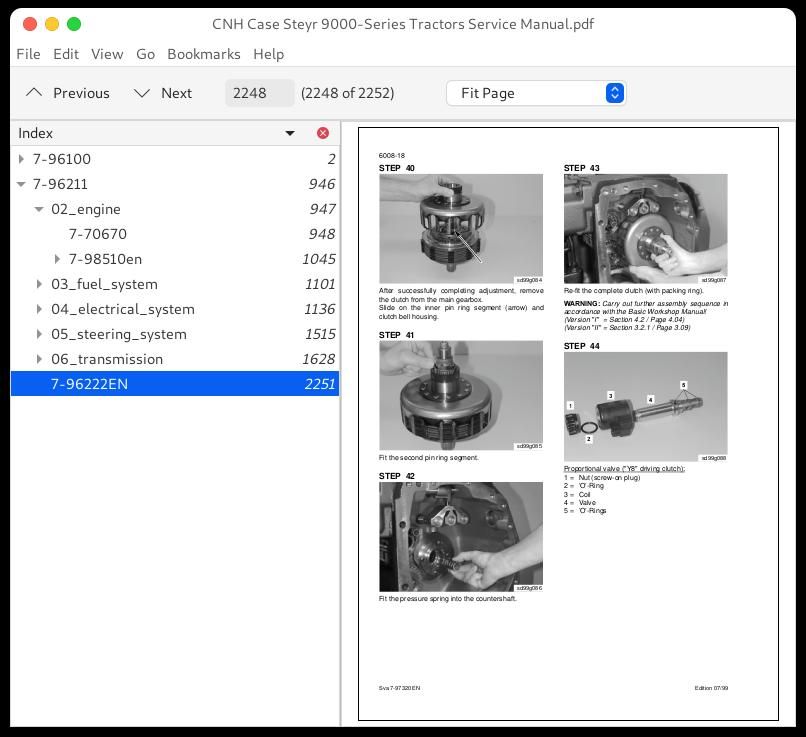
Adjusting the disk assembly air gap:...2238
Adjusting the Clutch Shaft and Crawler Gear Synchronisation...2246
7-96222EN...2251


