Freightliner Cascade Trucks Factory Service & Shop Manual
Catalog:
Model:
Complete workshop repair service manual with electrical wiring diagrams for Freightliner Cascadia Trucks. It's the same service manual used by dealers that guaranteed to be fully functional and intact without any missing page.
This Freightliner Cascadia service & repair manual (including maintenance, overhaul, disassembling & assembling, adjustment, tune-up, operation, inspecting, diagnostic & troubleshooting…) is divided into different sections. Each section covers a specific component or system with detailed illustrations. A table of contents is placed at the beginning of each section. Pages are easily found by category, and each page is expandable for great detail. The printer-ready PDF documents work like a charm on all kinds of devices.
“STI-481, S7 (9_10P).pdf”
Freightliner Cascadia Workshop Manual
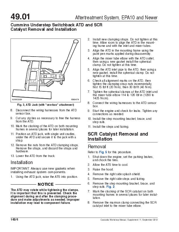
Models: CA125DC CA125SLP
STI-481, S7 (9/10P); 1,469 pages
Workshop Manual Contents
Group No. Group Title
00............. General Information
01.............. Engine
09............ Air Intake
13............. Air Compressor
15............ Alternator and Starter
20.......... Engine Cooling/Radiator
25.............. Clutch
26.................. Transmission
30............. Throttle Control
31.......... Frame and Frame Components
32....... Suspension
33........ Front Axle
35........ Rear Axle
41......... Driveline
42.............. Brakes
46............. Steering
47............ Fuel
49............. Exhaust
54..... Electrical, Instruments, and Controls
60................ Cab
72........... Doors
82.......... Windshield Wipers and Washer
88..... Hood, Grille, and CabFenders
91 ...... Seats and Restraint Systems
98............... Paint
…
— — — — — — — — — — — — — — — — — — — — — — — — — — —
“STI-478-6 (6_14).pdf”
Freightliner Cascadia Maintenance Manual
Models: CA113DC CA113SLP CA125DC CA125SLP
STI-478-6 (6/14); 140 pages
— — — — — — — — — — — — — — — — — — — — — — — — — — —
“Troubleshooting Manual.pdf”
928 pages
— — — — — — — — — — — — — — — — — — — — — — — — — — —
“Troubleshooting Manuals”
├── 1-General
│ ├── 02-Electrical System Overview
│ │ ├── 01-Electrical System and Main PDM Overview.pdf
│ │ ├── 02-Datalink Communication Structure.pdf
│ │ ├── 03-Central Gateway.pdf
│ │ ├── 04-SAM Cab.pdf
│ │ ├── 05-SAM Chassis.pdf
│ │ ├── 06-Modular Switch Field.pdf
│ │ └── 07-Common Powertrain Controller.pdf
│ ├── 03-Datalinks
│ │ ├── 01-Datalink, J1587_J1708.pdf
│ │ ├── 02-Datalink, J1939.pdf
│ │ ├── 03-Datalink, Cabin CAN.pdf
│ │ └── 04-Datalink, Diagnostic CAN.pdf
│ └── 04-Fault Codes
│ ├── 01-J1587 Fault Codes.pdf
│ ├── 02-J1939 Fault Codes.pdf
│ └── 03-CAN Fault Codes.pdf
├── 2-Powertrain Systems
│ ├── 01-Engine
│ │ └── 01-Starting and Charging.pdf
│ ├── 02-Transmission and Clutch
│ │ ├── 01-Clutch.pdf
│ │ ├── 02-Manual Transmission.pdf
│ │ ├── 03-Automated Manual Transmission with SmartShift.pdf
│ │ └── 04-Automatic Transmission.pdf
│ ├── 04-Standard Functions
│ │ └── 02-Virtual Technician.pdf
│ └── 06-Natural Gas Fuel Systems
│ └── 01-Compressed Natural Gas System.pdf
├── 3-Cab Systems
│ ├── 01-Instrument Cluster
│ │ ├── 01-ICU3 Instrument Cluster.pdf
│ │ ├── 02-ICU4_ICU4M Instrument Cluster.pdf
│ │ └── 03-ICU4Me Instrument Cluster.pdf
│ ├── 02-HVAC
│ │ ├── 01-HVAC System.pdf
│ │ └── 03-ParkSmart Auxiliary HVAC System.pdf
│ ├── 03-Audio System
│ │ └── Audio System.pdf
│ ├── 04-Exterior Lighting
│ │ ├── 01-Lighting System Overview.pdf
│ │ ├── 02-Headlight System.pdf
│ │ ├── 03-Daytime Running Lights.pdf
│ │ ├── 04-Stop, Turn, and Hazard Lights.pdf
│ │ ├── 05-Tail and Marker Lights.pdf
│ │ ├── 06-Fog Lights.pdf
│ │ └── 07-Trailer Lights.pdf
│ ├── 05-Interior Lighting
│ │ ├── 01-Dome Lighting.pdf
│ │ ├── 02-Sleeper Lighting.pdf
│ │ └── 03-Panel Backlighting.pdf
│ ├── 06-Standard Functions
│ │ ├── 01-Windshield Washer_Wiper.pdf
│ │ ├── 03-Door Locks.pdf
│ │ ├── 04-Horn.pdf
│ │ ├── 05-Heated Mirrors.pdf
│ │ ├── 06-Power Mirrors.pdf
│ │ ├── 07-Cab Power Receptacles.pdf
│ │ ├── 08-Power Windows.pdf
│ │ ├── 09-Power Management.pdf
│ │ └── 10-Ambient Air Temperature Sensor.pdf
│ ├── 07-Optional Functions
│ │ ├── 01-Backup Lights and Alarm.pdf
│ │ ├── 02-Heated Seats.pdf
│ │ ├── 03-Spare Power Feed Outputs.pdf
│ │ ├── 08-J1587_J1708 Air Bag and Rollover Protection System.pdf
│ │ ├── 11-J1939 Air Bag and Rollover Protection System.pdf
│ │ └── 12-Virtual Technician.pdf
│ ├── 08-Cruise Control & Collision Warning
│ │ ├── 01-Cruise Control.pdf
│ │ ├── 02-Predictive Cruise Control.pdf
│ │ ├── 03-VORAD Adaptive Cruise Control and Collision Warning System.pdf
│ │ └── 05-Detroit Assurance Radar.pdf
│ └── 09-Natural Gas
│ └── 01-Natural Gas Leak Detection System.pdf
├── 4-Chassis Systems
│ ├── 01-Brakes
│ │ ├── 01-ABS and Stability Control Systems.pdf
│ │ ├── 04-Low Air Pressure Warning System.pdf
│ │ ├── 05-Parking Brake Warning.pdf
│ │ ├── 06-Air Supply System.pdf
│ │ ├── 08-Service Brakes, Air System.pdf
│ │ └── 09-Parking Brake System.pdf
│ ├── 02-Steering
│ │ └── 01-Power Steering System.pdf
│ └── 03-Driveline
│ └── 01-Drivelines.pdf
├── Cascadia Guide 2009.pdf
├── Cascadia Guide 2012.pdf
├── Central Gateway Fault Codes 6.0.pdf
├── MSF Fault Codes 6.0.pdf
├── SAM Cab Fault Codes 6.0.pdf
├── SAM Chassis Fault Codes 6.0.pdf
├── SAM Wall Chart 5.0-5.4 EPA 2007.pdf
└── SAM Wall Chart 6.0 EPA 2010.pdf
EXCERPT:
Identifying Bubble Types
Vapor Bubbles
Vapor bubbles are harmless and are present in all diesel fuel systems. Vapor bubbles are often mistaken for air bubbles, but do not affect engine performance.
Vapor bubbles (see Fig. 1) may be visible in a diagnostic sight tube installed between the fuel/water separator and the fuel pump. They consist of harmless fuel vapor and trapped air, may vary from champagne-size to 1/4-inch (6-mm) diameter, and may increase in volume or size as the engine rpm increases. The lower pressure inside a fuel/water separator filter, caused by the suction of the fuel pump pulling fuel through the fuel/water separator, creates vapor bubbles. These vapor bubbles are normal and harmless to engine operation. In the fuel pump, the fuel is pressurized and the vapor bubbles dissolve. Vapor bubbles do not appear on the fuel return side of the system.
There is no troubleshooting or repair procedure required for vapor bubbles. Vapor bubbles do not cause performance issues and will not be present downstream of the fuel pump.
Air and Gas Bubbles
Air or gas bubbles indicate harmful leaks, and can cause hard starting and impaired engine performance. All diesel fuel holds some trapped air, caused by the natural splashing that occurs in the fuel tank. But excessive air bubbles, severe enough to degrade engine performance, indicate an air leak on the suction side of the fuel system, from the fuel tank into the fuel pump.
…


