JCB 2CX, 2DX, 210, 212 & Variants Backhoe Loader Factory Service & Shop Manual
Catalog:
Model:
Complete workshop repair service manual with electrical wiring diagrams for JCB Backhoe Loader 2CX, 2DX, 210, 210S, 210SL, 212, 212S & Variants. It's the same service manual used by dealers that guaranteed to be fully functional and intact without any missing page.
This JCB Backhoe Loader 2CX, 2DX, 210, 210S, 210SL, 212, 212S & Variants service & repair manual (including maintenance, overhaul, disassembling & assembling, adjustment, tune-up, operation, inspecting, diagnostic & troubleshooting…) is divided into different sections. Each section covers a specific component or system with detailed illustrations. A table of contents is placed at the beginning of each section. Pages are easily found by category, and each page is expandable for great detail. The printer-ready PDF documents work like a charm on all kinds of devices.
9802-8860 - JCB 212SU LE Backhoe Loader Part Catalog.pdf
9803-7110 - JCB 2CX, 2DX, 210, 212 & Variants Backhoe Loader Service Manual.pdf
9803-7130 - JCB 210S, 210SL, 212S Backhoe Loader Service Manual.pdf
9813-0600 - JCB 2DX BSIII India Backhoe Loader Service Manual.pdf
EXCERPT:
Section 1 - General Information
Section 2 - Care and Safety
Section 3 - Maintenance
Section B - Body and Framework
Section C - Electrics
Section D - Controls
Section E - Hydraulics
Section F - Transmissions
Section G - Brakes
Section H - Steering
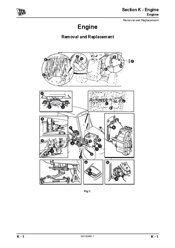
Section K - Engine
...
Removal and Replacement
Removal
1 Park the machine on firm level ground. Engage the parking brake and set the transmission to neutral.
2 Lower the loader shovel to the ground.
3 Make sure that the backhoe assembly is set central to the mainframe as shown. If necessary `sideshift' the backhoe into a central position.
4 Remove the stabiliser foot D, refit pivot pin to engage stabiliser ram.
5 K Fig 2. ( T B-68). Remove the inner leg:
a Disconnect hydraulic hoses to stabiliser ram.
b Use suitable lifting equipment, lift the inner leg clear.
c Remove the wear pads.
Replacement
Replacement is a reversal of the removal sequence.
Select suitable size upper pads A to achieve a maximum permissible float of 1 mm (0.039 in).
Make sure that the bottom pads C are held in position before guiding the inner leg into position. If the lower pads are not secured then the inner leg could dislodge the pads during assembly.
When the inner leg is in position adjust the bottom pads.
K Wear Pad - Adjustment ( T B-66).
Apply a high pressure grease such as JCB HP Grease (part number 4003/2000) to the threads of pad B.
...


