JCB WLS 434S Factory Service & Shop Manual
Catalog:
Model:
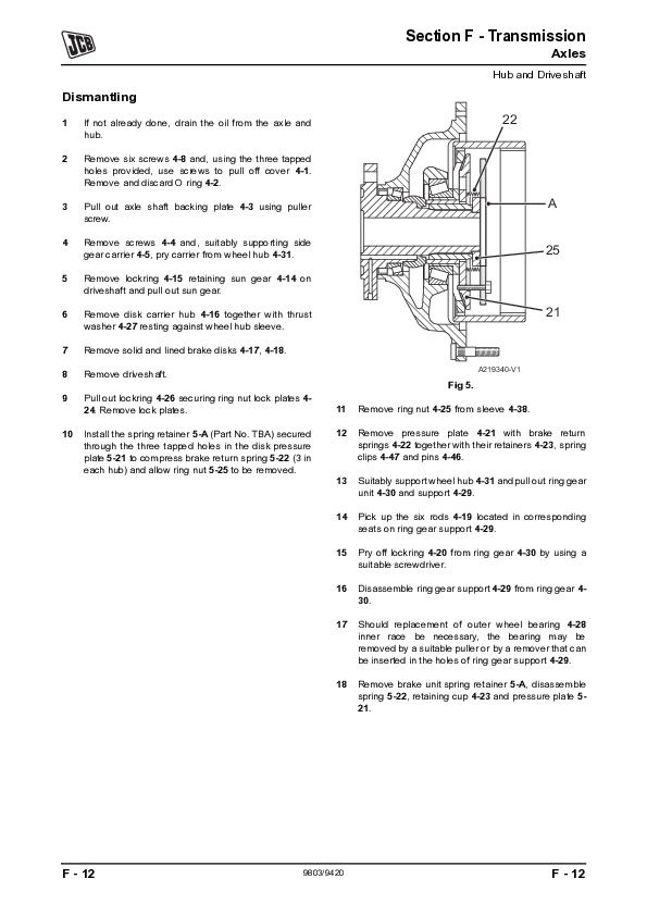
Complete workshop repair service manual with electrical wiring diagrams for JCB Wheeled Loading Shovel (WLS) 434S. It's the same service manual used by dealers that guaranteed to be fully functional and intact without any missing page.
This JCB Wheeled Loading Shovel (WLS) 434S service & repair manual (including maintenance, overhaul, disassembling & assembling, adjustment, tune-up, operation, inspecting, diagnostic & troubleshooting…) is divided into different sections. Each section covers a specific component or system with detailed illustrations. A table of contents is placed at the beginning of each section. Pages are easily found by category, and each page is expandable for great detail. The printer-ready PDF documents work like a charm on all kinds of devices.
9803-9420 - JCB Wheeled Loading Shovel (WLS) 434S Service Manual.pdf
EXCERPT:
Service Manual
Wheeled Loading Shovel - 434S
Section 1 - General Information
Section 2 - Care and Safety
Section 3 - Routine Maintenance
Section A - Attachments
Section B - Body and Framework
Section C - Electrics
Section E - Hydraulics
Section F - Transmission
Section G - Brakes
Section H - Hydraulic Steering
Section K - Engine
...
Typical Ram
Dismantle and Assembly
K Fig 66. ( T E-100). The numerical sequence shown on the illustration is intended as a guide to dismantling.
Dismantle
1 Place ram assembly on a locally manufactured strip/ rebuild bench. K Fig 65. ( T E-99).
Fig 65.
2 Use the correct size spanner to release end cap 66-1 and remove the piston rod assembly 66-9 from the cylinder.
!MWARNING
If air or hydraulic pressure is used to force out the piston assembly, ensure that the end cap is securely fitted. Severe injury can be caused by a suddenly released piston rod.
3 Position piston rod assembly on bench in place of ram cylinder. Remove seals 66-5, 66-6 and wear ring 66-4, 66-7 from piston head 66-3.
4 Extract dowel 66-2 from the piston head using the appropriate sized screw threaded into the extractorhole.
5 Use the correct size spanner, remove piston head 66- 3 from rod 66-9 and remove ‘O’ ring 66-8.
6 Remove gland bearing and end cap 66-1 from piston rod and remove the ‘O’ ring 66-10, wiper seal 66-12 and rod seal 66-11. Check end cap bearing for damage, scores or nicks. If damaged, the bearing must be replaced as part of the end cap assembly.
7 Ensure that metal components are free from scoring, nicks and burrs. A damaged piston rod will impair the life of the gland seals. Check the bore of the ram cylinder for damage.
...


