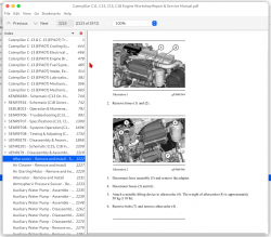
Caterpillar C13, C15 & C18 Engines Factory Service & Shop Manual
Catalog:
Model:
Complete workshop repair & service manual with electrical wiring diagrams for Caterpillar C13, C15 & C18 Engines. It's the same service manual used by dealers that guaranteed to be fully functional and intact without any missing page.
This Caterpillar C13, C15 & C18 Engines service & repair manual (including maintenance, overhaul, disassembling & assembling, adjustment, tune-up, operation, inspecting, diagnostic & troubleshooting…) is divided into different sections. Each section covers a specific component or system with detailed illustrations. A table of contents is placed at the beginning of each section. Pages are easily found by category, and each page is expandable for great detail. The printer-ready PDF documents work like a charm on all kinds of devices.
MANUAL LIST:
RENR5042 - Troubleshooting (C13, C15 & C18 Industrial Engines)
RENR7934 - Schematic (C18 Generator Set with EMCPII, EMCPII+, and EMCP3 Electrical System)
SENR9706 - Troubleshooting (C13, C15, & C18 Generator Set Engines)
SENR9707 - Specifications (C13, C15, & C18 Generator Set Engines)
SENR9708 - Systems Operation (C13, C15, & C18 Generator Set Engines)
SENR9708 - Testing & Adjusting (C13, C15, & C18 Generator Set Engines)
UENR0179 - Disassembly & Assembly (C18 Marine Engines)
UENR2648 - Schematic (C18 SCAC Marine Genset Electrical System)
UENR3201 - Schematic (C18 and C32 (Commercial) Alarm and Protection Electrical System)
UENR3226 - Schematic (C18 SCAC Marine Radiator Genset Electrical System)
UENR3426 - Specifications (C18 Marine Auxiliary & Marine Generator Set Engines)
UENR3427 - Systems Operation (C18 Marine Auxiliary and Marine Generator Set Engines)
UENR3427 - Testing & Adjusting (C18 Marine Auxiliary and Marine Generator Set Engines)
UENR5917 - Schematic (C18 SCAC Non-MCS Marine Genset Electrical System)
UENR8252 - Schematic (C18 SCAC Marine Radiator Genset Electrical System)
Caterpillar C-13 (EPA07) Cooling System (2009 Volvo VNL).pdf
Caterpillar C-13 (EPA07) Electrical System (2007 Volvo VNL).pdf
Caterpillar C-13 (EPA07) Engine Brake (2009 Volvo VNL).pdf
Caterpillar C-13 (EPA07) Fuel System (2009 Volvo VNL).pdf
Caterpillar C-13 (EPA07) Intake, Exhaust & Turbocharger.pdf
Caterpillar C-13 (EPA07) Lubrication System (2007 Volvo VNL).pdf
Caterpillar C-13 (EPA07) Mechanical (2008 Peterbilt 389).pdf
Caterpillar C-13 (EPA07) Mechanical (2009 Volvo VNL).pdf
Caterpillar C-13 & C-15 (EPA07) Troubleshooting (2007 Volvo VNL).pdf
SEBU8013 - Operation & Maintenance Manual (C18 Marine Generator Set).pdf
...
EXCERPT:
Inlet air passes through the air cleaner into the air inlet (8) of the turbocharger compressor wheel (10).
The turbocharger will supply more volume of air into the engine. This compressing of the air is referred to as boost. The compressing of air causes the air temperature to rise to about 204 °C (400 °F). As the air flows through the aftercooler (7) the temperature of the compressed air lowers to about 46 °C (115 °F).
Cooling of the inlet air causes the air to become more dense. This increases combustion efficiency and this increases horsepower output.
From the aftercooler, air enters the inlet manifold (3). Air flow from the inlet manifold (3) into the cylinders is controlled by inlet valves (1). There are two inlet valves and two exhaust valves (2) for each cylinder. The inlet valves open at the top center position before the piston moves toward the bottom center position. This is called the inlet stroke. When the inlet valves open, cooled compressed air from the inlet port enters the cylinder. The inlet valves close as the piston reaches the bottom center position.
The piston begins to travel back to the top center position on the compression stroke. The air in the cylinder is compressed to a very high temperature. When the piston is near the end of the compression stroke, fuel is injected into the cylinder and mixes with the air. This causes combustion to start in the cylinder. Once combustion starts, the combustion force pushes the piston toward the bottom center position. This is called the power stroke. The exhaust valves open when the piston moves toward the bottom center position and the exhaust gases are pushed through the exhaust port into exhaust manifold (4) as the piston travels toward top center on the exhaust stroke. The exhaust valves close and the cycle starts again. The complete cycle consists of four strokes:
...


