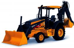
John Deere 310K Backhoe Loader Operation & Test Technical Manual (TM12435)
Catalog:
Model:
Complete technical Operation & Test Manual with electrical wiring diagrams for John Deere 310K Backhoe Loader. It's the same service manual used by dealers that guaranteed to be fully functional and intact without any missing page.
John Deere 310K Backhoe Loader Operation & Test Technical Manual (including maintenance, overhaul, disassembling & assembling, adjustment, tune-up, operation, inspecting, diagnostic & troubleshooting…) is divided into different sections. Each section covers a specific component or system with detailed illustrations. A table of contents is placed at the beginning of each section. Pages are easily found by category, and each page is expandable for great detail. The printer-ready PDF documents work like a charm on all kinds of devices.
TM12435 - John Deere 310K Backhoe Loader Operation and Test Technical Manual.pdf
EXCERPT:
TM12435 - 310K Backhoe Loader
Power Train Overview
Power Train Overview
XJ1162375-UN: Power Train Overview (shown with mechanical front wheel drive)
LEGEND:
1 - Pump Drive Shaft
2 - Mechanical Front Wheel Drive (MFWD) Output Shaft (if equipped)
3 - Mechanical Front Wheel Drive (MFWD) Clutch (if equipped)
31 - Transmission Pump
36 - Torque Converter
45 - First Speed Clutch
46 - Second Speed Clutch
59 - Low Range Forward Clutch
60 - High Range Forward Clutch
61 - Reverse Clutch
70 - Transmission
NOTE:
For locations of components, see Power Train Component Location . (Group 9020-15.)
The power train consists of the following components:
Front Axle (non-powered)
Mechanical Front Wheel Drive (MFWD) Axle (if equipped)
Drive Shaft (MFWD) (if equipped)
Torque Converter
Transmission Pump
Transmission
Drive Shaft (rear)
Rear Axle
Differential Lock
Park Brake
A single stage dual phase torque converter (36) drives a hydraulically engaged four speeds forward and two speeds reverse countershaft type power shift transmission (70).
Five clutch packs provide four forward and two reverse speeds. Two clutch packs must be engaged for movement. For forward, one directional clutch pack, either low-range forward or highrange forward, and one speed range clutch pack, either first or second. For reverse, the reverse directional clutch pack needs to be engaged and one speed range clutch pack either first or second.
The transmission pump (31) is a gear type pump. The transmission pump is driven at engine speed through the impeller drive from the torque converter. For information on how the transmission pump operates, see Transmission Pump Operation . (Group 9020-05.)
The transmission may also have an optional front axle mechanical front wheel drive (MFWD) output shaft (2) which is hydraulically applied and spring released.
The optional MFWD front axle consists of an open differential with outboard planetary final drives. For more information on how the MFWD operates, see Mechanical Front Wheel Drive (MFWD)
Operation—If Equipped . (Group 9020-05.)
The rear axle is an outboard planetary design with internal wet multi-disk service brakes that are self adjusting. Pressure oil for the service brakes is supplied by a foot operated brake valve. For information on how the differential operates, see Differential Operation . (Group 9020-05.)
The park brake is a wet multi-disk design which is spring applied and hydraulically released. For information on how the park brake operates, see Park Brake Operation . (Group 9020-05.)
The differential lock is a sliding sleeve design, which is hydraulically engaged and spring released. For information on how the differential lock operates, see Differential Lock Operation . (Group 9020-05.)
...


