Complete Repair Technical Manual for John Deere 329E and 333E Backhoe Loader. It's the same service manual used by dealers that guaranteed to be fully functional and intact without any missing page.
John Deere 329E and 333E Backhoe Loader Repair Technical Manual (including maintenance, overhaul, disassembling & assembling, adjustment, tune-up, operation, inspecting, diagnostic & troubleshooting…) is divided into different sections. Each section covers a specific component or system with detailed illustrations. A table of contents is placed at the beginning of each section. Pages are easily found by category, and each page is expandable for great detail. The printer-ready PDF documents work like a charm on all kinds of devices.
TM12808 - 329E and 333E Compact Track Loaders Technical Manual (Repair).pdf
tm12808 - 328E, 329E, 332E, and 333E Skid Steer and Compact Track Loader
Table of Contents
Foreword
Manual Identification—READ THIS FIRST!
Section 00: General Information
Group 0001: Safety
Recognize Safety Information
Follow Safety Instructions
Operate Only If Qualified
Wear Protective Equipment
Avoid Unauthorized Machine Modifications
Inspect Machine
Stay Clear of Moving Parts
Avoid High-Pressure Fluids
Avoid High-Pressure Oils
Work In Ventilated Area
Prevent Fires
Prevent Battery Explosions
Handle Chemical Products Safely
Decommissioning — Proper Recycling and Disposal of Fluids and Components
Prepare for Emergencies
Clean Debris from Machine
Use Steps and Handholds Correctly
Start Only From Operator's Seat
Use and Maintain Seat Belt
Prevent Unintended Machine Movement
Avoid Work Site Hazards
Keep Riders Off Machine
Avoid Backover Accidents
Avoid Machine Tip Over
Operating On Slopes
Operating or Traveling On Public Roads
Inspect and Maintain ROPS
Add and Operate Attachments Safely
Park and Prepare for Service Safely
Service Cooling System Safely
Remove Paint Before Welding or Heating
Make Welding Repairs Safely
Drive Metal Pins Safely
Handle Cab Door Safely
Clean Exhaust Filter Safely
Group 0003: Torque Values
Unified Inch Bolt and Screw Torque Values
Metric Bolt and Screw Torque Values
Additional Metric Cap Screw Torque Values
Check Oil Lines And Fittings
Service Recommendations for O-Ring Boss Fittings
Service Recommendations for 37° Flare and 30° Cone Seat Connectors
Service Recommendations for Flared Connections—Straight or Tapered Threads
Inch Series Four Bolt Flange Fitting For High Pressure Service Recommendations
Service Recommendations For Inch Series Four Bolt Flange Fittings
O-Ring Face Seal Fittings With SAE Inch Hex Nut and Stud End for High-Pressure Service Recommendations
O-Ring Face Seal Fittings With Metric Hex Nut And Stud End For Standard Pressure Service Recommendations
O-Ring Face Seal Fittings With Metric Hex Nut and Stud End for High-Pressure Service Recommendations
Service Recommendations for Metric Series Four Bolt Flange Fitting
Section 01: Wheels or Tracks
Group 0110: Powered Wheels and Fastenings
Wheel Remove and Install
Tire Remove and Install
Group 0130: Track System
Measure Rubber Track Height
Track Remove and Install
Track Roller Remove and Install
Drive Sprocket Remove and Install
Front or Rear Idler Remove and Install
Front Idler Yoke Assembly Remove and Install
Track Adjuster and Recoil Spring Assembly Remove and Install
Track Adjuster Recoil Spring Remove and Install
Track Adjuster Cylinder Disassemble and Assemble
Section 02: Axles and Suspension Systems
Group 0201: Drive Axle Housing and Support
Axle Housing Remove and Install
Axle Housing Disassemble and Assemble
Group 0250: Axle Shaft, Bearings, and Reduction Gears
Chain Case Access Plate Remove and Install
Drive Chain and Sprocket Remove and Install
Section 03: Transmission
Group 0315: Controls Linkage
Left and Right Joystick Remove and Install
Joystick Disassemble and Assemble
Group 0325: Flywheel Coupler
Hub Coupler Remove and Install
Group 0360: Hydraulic System
Hydrostatic and Hydraulic Start-Up Procedure
Hydrostatic Motor and Park Brake Remove and Install
Hydrostatic Motor and Park Brake Disassemble and Assemble
Hydrostatic Motor and Park Brake Disassemble and Assemble—Two Speed
Hydrostatic Motor, Park Brake, and Gear Case Repair
Hydrostatic Motor, Park Brake, and Gear Case Remove and Install
Hydrostatic Motor, Park Brake, and Gear Case Disassemble
Hydrostatic Motor, Park Brake, and Gear Case Inspection
Hydrostatic Motor, Park Brake, and Gear Case Assemble
Inspect Metal Face Seals
Gear Case Leakage Test
Hydrostatic Pump Remove and Install
Hydrostatic Pump Disassemble and Assemble
Charge Pump Remove and Install
Hydrostatic Control Valve Remove and Install
Hydrostatic Control Valve Disassemble and Assemble
Park Brake Solenoid Valve Remove and Install
Return Manifold Screen Remove and Install
Hydraulic Reservoir Return Screen Remove and Install
Section 04: Engine
Group 0400: Removal and Installation
John Deere Engine
Engine Remove and Install
Starter Motor Remove and Install
Accessory Drive Belt Tensioner Remove and Install
Damper Plate Remove and Install
Compressor Bracket Remove and Install
Engine Oil Dipstick Tube Remove and Install
Section 05: Engine Auxiliary System
Group 0510: Cooling Systems
Fan Remove and Install
Charge Air Cooler Remove and Install
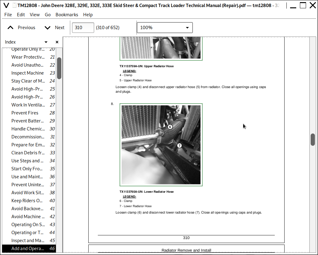
Radiator Remove and Install
Cooling Package Remove and Install
Group 0520: Intake System
Air Cleaner Remove and Install
Group 0530: External Exhaust Systems
Exhaust Tube Remove and Install
Diesel Particulate Filter (DPF) Remove and Install
Exhaust Filter Remove and Install
Group 0560: External Fuel Supply Systems
Fuel Tank Remove and Install
Low-Pressure Fuel Pump Remove and Install
Primary Fuel Filter and Water Separator Assembly Remove and Install
Final Fuel Filter Assembly Remove and Install
Section 17: Frame or Supporting Structure
Group 1740: Frame Installation
Welding On Machine
Welding Repair of Major Structure
Counterweight Remove and Install
Raising and Blocking Machine
Section 18: Operator's Station
Group 1800: Removal and Installation
Operator's Station Remove and Install
Group 1810: Operator Enclosure
Cab Door Remove and Install
Top Window Remove and Install
Rear Window Remove and Install
Side Window Remove and Install
Raising Operator's Station
Group 1821: Seat and Seat Belt
Seat Remove and Install
Seat Belt Remove and Install
Interlocking Seat Bar Remove and Install
Seat Air Spring Remove and Install
Group 1830: Heating and Air Conditioning
Refrigerant Cautions and Proper Handling
Flush and Purge Air Conditioner System
R134a Refrigerant Oil Information
R134a Refrigerant Recovery, Recycling, and Charging Station Installation Procedure
Recover R134a Refrigerant
Evacuate R134a System
Charge R134a System
Air Conditioner Compressor Remove and Install
Expansion Valve Remove and Install
Receiver-Dryer Remove and Install
Condenser Remove and Install
Air Conditioner and Heater Remove and Install
Evaporator Remove and Install
Blower Fan Remove and Install
Heater Core Remove and Install
Section 19: Sheet Metal and Styling
Group 1910: Hood or Engine Enclosure
Footwell Remove and Install
Side Panel Remove and Install
Engine Cover Remove and Install
Section 20: Safety and Convenience
Group 2001: Radio
Radio Antenna Remove and Install
Section 21: Main Hydraulic System
Group 2160: Hydraulic System
General Oil Cleanup Procedure
Hydraulic/Hydrostatic Component Failure Cleanup Procedure
Vacuum Pump Installation
Hydraulic Fan Motor Remove and Install
Hydraulic Oil Cooler Remove and Install
Hydraulic Oil Reservoir Remove and Install
Hydraulic Pump Remove and Install
Hydraulic Pump Disassemble and Assemble
High Flow Hydraulic Pump Disassemble and Assemble
Section 31: Loader
Group 3104: Attachment Coupler
Quik-Tatch™ Coupler Remove and Install
Quik-Tatch™ Actuator Remove and Install
Group 3140: Frame
Upper Boom Link Remove and Install
Lower Boom Link Remove and Install
Boom Remove and Install
Boom Lock Remove and Install
Boom Lock Disassemble and Assemble
Boom Lock
Group 3160: Hydraulic System
Control Valve Remove and Install
Control Valve Disassemble and Assemble
Self Leveling Valve Remove and Install
Ride Control Accumulator Remove and Install
Ride Control Valve Remove and Install
Ride Control Valve Disassemble and Assemble
Boom Cylinder Remove and Install
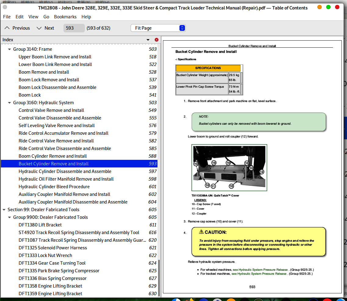
Bucket Cylinder Remove and Install
Hydraulic Cylinder Disassemble and Assemble
Hydraulic Oil Filter Manifold Remove and Install
Hydraulic Cylinder Bleed Procedure
Auxiliary Coupler Manifold Remove and Install
Auxiliary Coupler Manifold Disassemble and Assemble
Section 99: Dealer Fabricated Tools
Group 9900: Dealer Fabricated Tools
DFT1380 Lift Bracket
ST4920 Track Recoil Spring Disassembly and Assembly Tool
DFT1087 Track Recoil Spring Disassembly and Assembly Guard Tool
DFT1325 Solenoid Power Harness
DFT1333 Lock Nut Wrench
DFT1334 Gear Case Turning Tool
DFT1335 Park Brake Spring Compressor
DFT1336 Bias Spring Compressor
DFT1358 Engine Lifting Bracket
DFT1359 Engine Lifting Bracket