John Deere 524K 4WD Loader Operation & Test Technical Manual (TM10686)
Catalog:
Model:
Complete technical Operation & Test Manual with electrical wiring diagrams for John Deere 524K 4WD Loader. It's the same service manual used by dealers that guaranteed to be fully functional and intact without any missing page.
John Deere 524K 4WD Loader Operation & Test Technical Manual (including maintenance, overhaul, disassembling & assembling, adjustment, tune-up, operation, inspecting, diagnostic & troubleshooting…) is divided into different sections. Each section covers a specific component or system with detailed illustrations. A table of contents is placed at the beginning of each section. Pages are easily found by category, and each page is expandable for great detail. The printer-ready PDF documents work like a charm on all kinds of devices.
TM10686 - John Deere 524K 4WD Loader [Engine 6068HDW74 (T3)] Technical Manual (Operation & Test).pdf
CONTENTS
Foreword
9000 - General Information
9001 - Diagnostic Trouble Codes (DTC)
9005 - Operational Checkout Procedure
9010 - Engine
9015 - Electrical System
9020 - Power Train
9025 - Hydraulic System
9031 - Heating and Air Conditioning
...
!!! # Generated bmk file
Contents.....3
General Information.....5
Safety Information.....7
Recognize Safety Information.....7
Follow Safety Instructions.....7
Operate Only If Qualified.....7
Wear Protective Equipment.....8
Avoid Unauthorized Machine Modifications.....8
Add Cab Guarding For Special Uses.....8
Inspect Machine.....9
Stay Clear of Moving Parts.....9
Avoid High-Pressure Fluids.....9
Avoid High-Pressure Oils.....10
Beware of Exhaust Fumes.....10
Prevent Fires.....11
Clean Debris from Machine.....11
Prevent Battery Explosions.....12
Handle Chemical Products Safely.....12
Dispose of Waste Properly.....12
Prepare for Emergencies.....13
Use Steps and Handholds Correctly.....13
Start Only From Operator's Seat.....13
Use and Maintain Seat Belt.....13
Prevent Unintended Machine Movement.....14
Avoid Work Site Hazards.....15
Use Special Care When Operating Loader.....16
Keep Riders Off Machine.....16
Avoid Backover Accidents.....16
Avoid Machine Tip Over.....17
Operating on Slopes.....17
Operating or Traveling On Public Roads.....18
Inspect and Maintain ROPS.....18
Add and Operate Attachments Safely.....18
Park And Prepare For Service Safely.....19
Service Cooling System Safely.....19
Service Tires Safely.....20
Remove Paint Before Welding or Heating.....20
Make Welding Repairs Safely.....21
Drive Metal Pins Safely.....21
Diagnostic Trouble Codes (DTC).....34
Engine Control Unit (ECU) Diagnostic Trouble Codes.....35
Engine Control Unit (ECU) Diagnostic Trouble Codes.....35
000107.00 — Eng Air Filter Restricted.....35
Engine Air Filter Restricted Diagnostic Procedure.....35
000171.03 — Ambient Air Temperature Out of Range High.....36
Ambient Air Temperature Out of Range High Diagnostic Procedure.....36
000171.04 — Ambient Air Temperature Out of Range Low.....37
Ambient Air Temperature Out of Range Low Diagnostic Procedure.....37
000627.01 — ECU Unswitched Power Short to Ground.....38
ECU Unswitched Short to Ground Diagnostic Procedure.....38
000676.05 — Engine Heat Open or Short.....39
Engine Heat Open or Short Diagnostic Procedure.....39
001253.13 — Injector Cal Required.....41
Injector Calibration Required Diagnostic Procedure.....41
001321.31 — Starter Solenoid Open Circuit.....42
Starter Solenoid Open Circuit Diagnostic Procedure.....42
002003.09 — CAN Communication Lost for TCU.....44
CAN Communication Lost For TCU Diagnostic Procedure.....44
002033.09 — CAN Communication Lost for FLC.....45
CAN Communication Lost for FLC Diagnostic Procedure.....45
003587.05 — Ether Starting Aid Circuit Fault.....47
Ether Solenoid Open or Short Diagnostic Procedure.....47
Transmission Control Unit (TCU) Diagnostic Trouble Codes.....49
Transmission Control Unit (TCU) Diagnostic Trouble Codes.....49
000091.09 — Timeout EEC2 Message.....49
Timeout EEC2 Message Diagnostic Procedure.....49
000513.02 — Percent Torque Invalid.....50
Percent Torque Invalid Diagnostic Procedure.....50
000513.09 — Timeout EEC1 Message.....51
Timeout EEC1 Message Diagnostic Procedure.....51
000514.02 — Friction Invalid.....52
Friction Invalid Diagnostic Procedure.....52
000514.09 — Timeout EEC3 Message.....53
Timeout EEC3 Message Diagnostic Procedure.....54
000544.02 — Ref Torque Invalid.....55
Ref Torque Invalid Diagnostic Procedure.....55
000544.09 — Timeout Engine Config Message.....56
Timeout Engine Config Message Diagnostic Procedure.....56
000777.02 — TC Clutch Slippage.....57
TC Clutch Slippage Diagnostic Procedure.....57
000777.03 — TC Lockup Sol Short to Power.....59
TC Lockup Sol Short to Power Diagnostic Procedure.....59
000777.04 — TC Lockup Sol Short to Gnd.....60
TC Lockup Sol Short to Gnd Diagnostic Procedure.....60
000777.05 — TC Lockup Sol Open Circuit.....62
TC Lockup Sol Open Circuit Diagnostic Procedure.....62
000928.03 — Axle Disconnect Solenoid Short to Power.....62
Axle Disconnect Solenoid Short to Power Diagnostic Procedure.....63
000928.04 — Axle Disconnect Solenoid High Current.....64
Axle Disconnect Solenoid High Current Diagnostic Procedure.....64
000928.05 — Axle Disconnect Solenoid Open Circuit.....65
Axle Disconnect Solenoid Open Circuit Diagnostic Procedure.....65
002033.09 — CAN Communication Lost for FLC.....66
CAN Communication Lost for FLC Diagnostic Procedure.....67
002141.09 — CAN Communication Lost for SSM.....68
CAN Communication Lost for SSM Diagnostic Procedure.....69
522344.00 — Torque Converter Output Temperature Too High.....70
Torque Converter Output Temperature Too High Diagnostic Procedure.....70
522350.15 — Transmission Input Torque Overload.....71
Transmission Input Torque Overload Diagnostic Procedure.....71
522364.07 — Transmission Clutch Calibration Failed.....72
Transmission Clutch Calibration Failed Diagnostic Procedure.....72
522364.13 — Transmission Clutch Calibration Fault.....73
Transmission Clutch Calibration Fault Diagnostic Procedure.....73
522365.13 — Limp Home Mode Requested.....74
Limp Home Mode Requested Diagnostic Procedure.....74
522366.13 — Application Invalid.....74
Application Invalid Diagnostic Procedure.....75
522367.13 — TCU Configuration Invalid.....75
TCU Configuration Invalid Diagnostic Procedure.....75
522368.02 — TCU Memory Failure.....76
TCU Memory Failure Diagnostic Procedure.....76
522369.03 — Remote Display Short to Power.....76
Remote Display Short to Ground Diagnostic Procedure.....77
522370.02 — TCU Valve Power Supply 2 Short Circuit.....78
TCU Valve Power Supply 2 Short Circuit Diagnostic Procedure.....78
522371.02 — TCU Valve Power Supply 1 Short Circuit.....80
TCU Valve Power Supply 1 Short Circuit Diagnostic Procedure.....80
522373.03 — Power Supply High Voltage.....81
Power Supply High Voltage Diagnostic Procedure.....81
522373.04 — Power Supply Low Voltage.....81
Power Supply Low Voltage Diagnostic Procedure.....82
522374.03 — Sensor Supply Short to Power.....83
Sensor Supply Short to Power Diagnostic Procedure.....83
522374.04 — Sensor Supply Short to Ground.....84
Sensor Supply Short to Ground Diagnostic Procedure.....84
522375.00 — Transmission Oil Filter Restricted.....85
Transmission Oil Filter Restricted Diagnostic Procedure.....85
522376.00 — Transmission Oil Temperature Over Maximum Value.....87
Transmission Oil Temperature Over Maximum Value Diagnostic Procedure.....87
522379.03 — Park Brake Release Solenoid Short to Power.....88
Park Brake Release Solenoid Short to Power Diagnostic Procedure.....88
522379.04 — Park Brake Release Solenoid Short to Ground.....90
Park Brake Release Solenoid Short to Ground Diagnostic Procedure.....90
522379.05 — Park Brake Release Solenoid Open Circuit.....92
Park Brake Release Solenoid Open Circuit Diagnostic Procedure.....92
522382.03 — Backup Alarm Short to Power.....93
Backup Alarm Short to Power Diagnostic Procedure.....93
522382.04 — Backup Alarm Short to Ground.....94
Backup Alarm Short to Ground Diagnostic Procedure.....94
522383.02 — Transmission Clutch KR Slippage.....95
Transmission Clutch KR Slippage Diagnostic Procedure.....95
522383.03 — Clutch Reverse Solenoid Short to Power.....97
Clutch Reverse Solenoid Short to Power Diagnostic Procedure.....97
522383.04 — Clutch Reverse Solenoid Short to Ground.....99
Clutch Reverse Solenoid Short to Ground Diagnostic Procedure.....99
522383.05 — Clutch Reverse Solenoid Open Circuit.....101
Clutch Reverse Solenoid Open Circuit Diagnostic Procedure.....101
522386.02 — Transmission Clutch KV Slippage.....102
Transmission Clutch KV Slippage Diagnostic Procedure.....102
522386.03 — Clutch Forward Solenoid Short to Power.....104
Clutch Forward Solenoid Short to Power Diagnostic Procedure.....104
522386.04 — Clutch Forward Solenoid Short to Ground.....106
Clutch Forward Solenoid Short to Ground.....106
522386.05 — Clutch Forward Solenoid Open Circuit.....108
Clutch Forward Solenoid Open Circuit Diagnostic Procedure.....108
522389.02 — Transmission Clutch K4 Slippage.....109
Transmission Clutch K4 Slippage Diagnostic Procedure.....109
522389.03 — Clutch K4 Solenoid Short to Power.....111
Clutch K4 Solenoid Short to Power Diagnostic Procedure.....111
522389.04 — Clutch K4 Solenoid Short to Ground.....113
Clutch K4 Solenoid Short to Ground Diagnostic Procedure.....113
522389.05 — Clutch K4 Solenoid Open Circuit.....115
Clutch K4 Solenoid Open Circuit Diagnostic Procedure.....115
522392.02 — Transmission Clutch K3 Slippage.....116
Transmission Clutch K3 Slippage Diagnostic Procedure.....116
522392.03 — Clutch K3 Solenoid Short to Power.....118
Clutch K3 Solenoid Short to Power Diagnostic Procedure.....118
522392.04 — Clutch K3 Solenoid Short to Ground.....120
Clutch K3 Solenoid Short to Ground Diagnostic Procedure.....120
522392.05 — Clutch K3 Solenoid Open Circuit.....122
Clutch K3 Solenoid Open Circuit Diagnostic Procedure.....122
522395.02 — Transmission Clutch K2 Slippage.....123
Transmission Clutch K2 Slippage Diagnostic Procedure.....123
522395.03 — Clutch K2 Solenoid Short to Power.....125
Clutch K2 Solenoid Short to Power Diagnostic Procedure.....125
522395.04 — Clutch K2 Solenoid Short to Ground.....127
Clutch K2 Solenoid Short to Ground Diagnostic Procedure.....127
522395.05 — Clutch K2 Solenoid Open Circuit.....129
Clutch K2 Solenoid Open Circuit Diagnostic Procedure.....129
522399.02 — Transmission Clutch K1 Slippage.....130
Transmission Clutch K1 Slippage Diagnostic Procedure.....130
522399.03 — Clutch K1 Solenoid Short to Power.....132
Clutch K1 Solenoid Short to Power Diagnostic Procedure.....132
522399.04 — Clutch K1 Solenoid Short to Ground.....134
Clutch K1 Solenoid Short to Ground Diagnostic Procedure.....134
522399.05 — Clutch K1 Solenoid Open Circuit.....136
Clutch K1 Solenoid Open Circuit Diagnostic Procedure.....136
522401.02 — Output Shaft Speed Sensor Fault.....137
Output Shaft Speed Sensor Fault Diagnostic Procedure.....137
522401.03 — Output Shaft Speed Sensor Open or Short.....138
Output Shaft Speed Sensor Open or Short Diagnostic Procedure.....138
522401.04 — Output Shaft Speed Sensor Short to Ground.....140
Output Shaft Speed Sensor Short to Ground Diagnostic Procedure.....140
522401.12 — Output Shaft Speed Sensor Fault.....142
Output Shaft Speed Sensor Fault Diagnostic Procedure.....142
522401.15 — Output Shaft Speed Sensor Overspeed.....143
Output Shaft Speed Sensor Overspeed Diagnostic Procedure.....143
522402.03 — Clutch Speed Sensor Open or Short.....144
Transmission Clutch Speed Sensor Open or Short Diagnostic Procedure.....144
522402.04 — Clutch Speed Sensor Short to Ground.....145
Clutch Speed Sensor Short to Ground Diagnostic Procedure.....145
522402.12 — Clutch Speed Sensor Fault.....147
Clutch Speed Sensor Fault Diagnostic Procedure.....147
522403.03 — Converter Output Speed Sensor Open or Short.....147
Converter Output Speed Sensor Open or Short Diagnostic Procedure.....148
522403.04 — Converter Output Speed Sensor Short to Ground.....149
Converter Output Speed Sensor Short to Ground Diagnostic Procedure.....149
522403.12 — Converter Output Speed Sensor Fault.....151
Converter Output Speed Sensor Fault Diagnostic Procedure.....151
522404.03 — Converter Input Speed Sensor Open or Short.....152
Converter Input Speed Sensor Open or Short Diagnostic Procedure.....152
522404.04 — Converter Input Speed Sensor Short to Ground.....154
Converter Input Speed Sensor Short to Ground Diagnostic Procedure.....154
522404.12 — Converter Input Speed Sensor Fault.....156
Converter Input Speed Sensor Fault Diagnostic Procedure.....156
522406.03 — Transmission Oil Temperature Sensor Open or Short.....156
Transmission Oil Temperature Sensor Open or Short Diagnostic Procedure.....157
522406.04 — Transmission Oil Temperature Sensor Short to Ground.....159
Transmission Oil Temperature Sensor Short to Ground Diagnostic Procedure.....159
522407.03 — Clutch Cut-off Sensor Short to Power.....161
Clutch Cut-off Sensor Short to Power Diagnostic Procedure.....161
522407.04 — Clutch Cut-off Sensor Open or Short.....162
Clutch Cut-off Sensor Open or Short Diagnostic Procedure.....162
522409.05 — 2nd FNR Open Circuit.....163
2nd FNR Open Circuit Diagnostic Procedure (Pilot Control Joystick FNR).....164
2nd FNR Open Circuit Diagnostic Procedure (Joystick Steering FNR).....165
522409.12 — 2nd FNR Multiple Inputs.....166
2nd FNR Multiple Inputs Diagnostic Procedure (Pilot Control Joystick FNR).....166
2nd FNR Multiple Inputs Diagnostic Procedure (Joystick Steering FNR).....168
522411.05 — 1st FNR Open Circuit.....169
1st FNR Open Circuit Diagnostic Procedure (Steering Column FNR).....170
1st FNR Open Circuit Diagnostic Procedure (Pilot Control Joystick FNR).....171
522411.12 — 1st FNR Multiple Inputs.....172
1st FNR Multiple Inputs Diagnostic Procedure (Steering Column FNR).....172
1st FNR Multiple Inputs Diagnostic Procedure (Pilot Control Joystick FNR).....174
522412.12 — Gear Selection Error.....175
Gear Selection Error Diagnostic Procedure.....176
522419.02 — Clutch Cut-off Disabled.....178
Clutch Cut-off Disabled Diagnostic Procedure.....178
522420.02 — Manual Downshift Disabled.....179
Manual Downshift Disabled Diagnostic Procedure.....179
522421.02 — Auto to 1st Disabled.....179
Auto to 1st Disabled Diagnostic Procedure.....179
524048.00 — Transmission Output Torque Exceeded.....180
Transmission Output Torque Exceeded Diagnostic Procedure.....180
524049.00 — Transmission Input Torque Exceeded.....180
Transmission Input Torque Exceeded Diagnostic Procedure.....181
524287.00 — Configure Machine Model.....181
Configure Machine Model Diagnostic Procedure.....181
Flex Load Controller (FLC) Diagnostic Trouble Codes.....183
Flex Load Controller (FLC) Diagnostic Trouble Codes.....183
000096.04 — Fuel Level Short to Ground.....183
Fuel Level Short to Ground Diagnostic Procedure.....183
000096.05 — Fuel Level Open or Short.....184
Fuel Level Open or Short Diagnostic Procedure.....184
000167.16 — Alternator High Voltage.....186
Alternator High Voltage Diagnostic Procedure.....187
000167.18 — Alternator Low Voltage.....187
Alternator Low Voltage Diagnostic Procedure.....187
000168.16 — High Battery Voltage.....188
High Battery Voltage Diagnostic Procedure.....188
000234.02 — Invalid TCU Software Rev.....189
Invalid TCU Software Rev Diagnostic Procedure.....189
000444.05 — 12 Volt Center Tap Open or Short.....189
12-Volt Center Tap Open or Short Diagnostic Procedure.....190
000444.18 — Battery Voltage Imbalance.....191
Battery Voltage Imbalance Diagnostic Procedure.....191
000521.00 — Brake Pedal High Voltage.....192
Brake Pedal High Voltage Diagnostic Procedure.....192
000628.12 — Controller Not Programmed.....193
Controller Not Programmed Diagnostic Procedure.....193
000629.12 — FLC Watchdog Time Out.....193
FLC Watchdog Time Out Diagnostic Procedure.....194
000639.12 — FLC CAN Failure.....194
FLC CAN Failure Diagnostic Procedure.....194
000639.14 — FLC CAN Bus Off.....195
FLC CAN Bus Off Diagnostic Procedure.....195
000746.05 — Differential Lock Solenoid Open or Short.....196
Differential Lock Solenoid Open or Short Diagnostic Procedure.....196
000746.06 — Differential Lock Solenoid High Current.....198
Differential Lock Solenoid High Current Diagnostic Procedure.....198
000785.05 — Pilot Solenoid Open or Short.....199
Pilot Solenoid Open or Short Diagnostic Procedure.....199
000785.06 — Pilot Solenoid High Current.....202
Pilot Solenoid High Current Diagnostic Procedure.....202
000880.06 — Brake Lights High Current.....204
Brake Lights High Current Diagnostic Procedure.....204
000977.05 — Reverse Fan Solenoid Open or Short.....205
Reverse Fan Solenoid Open or Short Diagnostic Procedure.....206
000977.06 — Reverse Fan Solenoid High Current.....208
Reverse Fan Solenoid High Current Diagnostic Procedure.....208
001069.02 — Tire Size Incorrect.....209
Tire Size Incorrect Diagnostic Procedure.....209
001071.05 — Fan Speed Solenoid Open or Short.....210
Fan Speed Solenoid Open or Short Diagnostic Procedure.....210
001071.06 — Fan Speed Solenoid High Current.....212
Fan Speed Solenoid High Current Diagnostic Procedure.....212
001503.04 — Arm Rest Down Switch Short to Ground.....214
Arm Rest Down Switch Short to Ground Diagnostic Procedure.....214
001503.11 — Arm Rest Position Undetermined.....215
Arm Rest Position Undetermined Diagnostic Procedure.....215
001550.06 — AC Clutch High Current.....218
AC Clutch High Current Diagnostic Procedure.....218
001565.04 — Arm Rest Up Switch Short to Ground.....219
Arm Rest Up Switch Short to Ground Diagnostic Procedure.....219
001638.00 — Hydraulic Oil High Temperature.....221
Hydraulic Oil High Temperature Diagnostic Procedure.....221
001638.04 — Hydraulic Oil Temperature Sensor Short to Ground.....222
Hydraulic Oil Temperature Sensor Short to Ground Diagnostic Procedure.....222
001713.01 — Hydraulic Oil Filter Restricted.....223
Hydraulic Oil Filter Restricted Diagnostic Procedure.....223
001762.03 — Hydraulic Pressure Sensor Short to Power.....225
Hydraulic Pressure Sensor Short to Power Diagnostic Procedure.....225
001762.04 — Hydraulic Pressure Sensor Open or Short.....226
Hydraulic Pressure Sensor Open or Short.....226
002000.09 — CAN Communication Lost for ECU.....228
CAN Communication Lost For ECU Diagnostic Procedure.....228
002003.09 — CAN Communication Lost for TCU.....230
CAN Communication Lost For TCU Diagnostic Procedure.....230
002040.09 — CAN Communication Lost for ADU.....232
CAN Communication Lost For ADU Diagnostic Procedure.....232
002051.09 — CAN Communication Lost for TPM.....234
CAN Communication Lost for TPM Diagnostic Procedure.....234
002052.09 — CAN Communication Lost for JSC.....235
CAN Communication Lost for JSC Diagnostic Procedure.....235
002129.09 — CAN Communication Lost for JSV.....237
CAN Communication Lost for JSV Diagnostic Procedure.....237
002132.09 — CAN Communication Lost for ROD.....239
CAN Communication Lost for ROD Diagnostic Procedure.....239
002141.09 — CAN Communication Lost for SSM.....241
CAN Communication Lost For SSM Diagnostic Procedure.....241
002169.09 — CAN Communication Lost for RDR.....242
CAN Communication Lost for RDR Diagnostic Procedure.....242
002350.05 — Drive Lamps Open or Short.....244
Drive Lamps Open or Short Diagnostic Procedure.....244
002350.06 — Drive Lamps High Current.....246
Drive Lamps High Current Diagnostic Procedure.....246
002355.05 — Front Work Lights Open or Short.....247
Front Auxiliary Lights Open or Short Diagnostic Procedure.....247
002355.06 — Front Work Lights High Current.....249
Front Work Lights High Current Diagnostic Procedure.....249
002356.05 — Front Work Lights Open or Short.....251
Front Work Lights Open or Short Diagnostic Procedure.....251
002356.06 — Front Work Lights High Current.....253
Front Work Lights High Current Diagnostic Procedure.....253
002359.05 — Machine Work Lights Open Circuit.....255
002359.06 — Machine Work Lights High Current.....255
002362.05 — Rear Work Lights Open or Short.....255
Rear Work Lights Open or Short Diagnostic Procedure.....255
002362.06 — Rear Work Lights High Current.....257
Rear Work Lights High Current Diagnostic Procedure.....257
002367.04 — Left Turn Switch Short to Ground.....259
Left Turn Switch Short to Ground Diagnostic Procedure.....259
002368.05 — Left Turn Lights Open or Short.....260
Left Turn Lights Open or Short Diagnostic Procedure.....260
002368.06 — Left Turn Lights High Current.....263
Left Turn Lights High Current Diagnostic Procedure.....263
002369.04 — Right Turn Switch Short to Ground.....264
Right Turn Switch Short to Ground Diagnostic Procedure.....264
002370.05 — Right Turn Lights Open or Short.....266
Right Turn Lights Open or Short Diagnostic Procedure.....266
002370.06 — Right Turn Lights High Current.....268
Right Turn Lights High Current Diagnostic Procedure.....268
002378.06 — Marker/Tail Lights High Current.....270
Marker/Tail Lights High Current Diagnostic Procedure.....270
002386.06 — Beacon Light High Current.....272
Beacon Light High Current Diagnostic Procedure.....272
002680.05 — RTC/Float Detent Open or Short.....273
RTC/Float Detent Open or Short Diagnostic Procedure.....273
002680.06 — RTC/Float Detent High Current.....275
RTC/Float Detent High Current Diagnostic Procedure.....275
002697.02 — Timeout JSC Message.....277
Timeout JSC Message Diagnostic Procedure.....277
002717.05 — RTD Detent Open or Short.....278
RTD Detent Open or Short Diagnostic Procedure.....278
002717.06 — RTD Detent High Current.....280
RTD Detent High Current Diagnostic Procedure.....280
002754.05 — BHKO Detent Open or Short.....282
BHKO Detent Open or Short Diagnostic Procedure.....282
002754.06 — BHKO Detent High Current.....284
BHKO Detent High Current Diagnostic Procedure.....284
002875.04 — Hazard Wakeup Short to Ground.....285
Hazard Wakeup Short to Ground Diagnostic Procedure.....285
003509.04 — FLC Sensor 1 Voltage Low.....287
FLC Sensor 1 Voltage Low Diagnostic Procedure.....287
003510.04 — FLC Sensor 2 Voltage Low.....288
FLC Sensor 2 Voltage Low Diagnostic Procedure.....288
003511.04 — FLC Sensor 3 Voltage Low.....290
FLC Sensor 3 Voltage Low Diagnostic Procedure.....290
299621.02 — Machine Configuration Invalid.....291
Machine Configuration Invalid Diagnostic Procedure.....291
522280.01 — Brake Pressure Low.....292
Brake Pressure Low Diagnostic Procedure.....292
522341.05 — Heated Mirror Open or Short.....293
Heated Mirror Open or Short Diagnostic Procedure.....293
522341.06 — Heated Mirror Short to Ground.....295
Heated Mirror Short to Ground Diagnostic Procedure.....295
522426.04 — Rear Wiper Park Short to Ground.....297
Rear Wiper Park Short to Ground Diagnostic Procedure.....297
522427.04 — Front Wiper Park Short to Ground.....298
Front Wiper Park Short to Ground Diagnostic Procedure.....298
522431.02 — Memory Test Failure.....299
Memory Test Failure Diagnostic Procedure.....299
522432.06 — Rear Wiper High Speed High Current.....300
Rear Wiper High Speed High Current Diagnostic Procedure.....300
522433.05 — Rear Wiper Low Speed Open or Short.....301
Rear Wiper Low Speed Open or Short Diagnostic Procedure.....301
522433.06 — Rear Wiper Low Speed High Current.....303
Rear Wiper Low Speed High Current Diagnostic Procedure.....303
522434.05 — Front Wiper Low Speed Open or Short.....305
Front Wiper Low Speed Open or Short Diagnostic Procedure.....305
522434.06 — Front Wiper Low Speed High Current.....306
Front Wiper Low Speed High Current Diagnostic Procedure.....307
522435.06 — Front Wiper High Speed High Current.....308
Front Wiper High Speed High Current Diagnostic Procedure.....308
522436.03 — Bucket Position Short to Power.....310
Bucket Position Short to Power Diagnostic Procedure.....310
522436.04 — Bucket Position Open or Short.....311
Bucket Position Open or Short Diagnostic Procedure.....311
522437.04 — Return-to-Dig Switch Short to Ground.....313
Return-to-Dig Switch Short to Ground Diagnostic Procedure.....313
522438.05 — Pin Disconnect Solenoid Open or Short.....314
Pin Disconnect Solenoid Open or Short Diagnostic Procedure.....314
522438.06 — Pin Disconnect Solenoid High Current.....316
Pin Disconnect Solenoid High Current Diagnostic Procedure.....317
522543.03 — Boom Cyl Rod Press Open or Short.....318
Boom Cyl Rod Press Open or Short Diagnostic Procedure.....318
522543.04 — Boom Cyl Rod Press Short to Ground.....320
Boom Cyl Rod Press Short to Ground Diagnostic Procedure.....320
522544.03 — Boom Cyl Head Press Open or Short.....322
Boom Cyl Head Press Open or Short Diagnostic Procedure.....322
522544.04 — Boom Cyl Head Press Short to Ground.....323
Boom Cyl Head Press Short to Ground Diagnostic Procedure.....324
522796.05 — Rear Washer Pump Open or Short.....325
Rear Washer Pump Open or Short Diagnostic Procedure.....325
522796.06 — Rear Washer Pump High Current.....327
Rear Washer Pump High Current Diagnostic Procedure.....327
522797.05 — Front Washer Pump Open or Short.....329
Front Washer Pump Open or Short Diagnostic Procedure.....329
522797.06 — Front Washer Pump High Current.....330
Front Washer Pump High Current Diagnostic Procedure.....331
523137.01 — Steering Pressure Low.....332
Steering Pressure Low Diagnostic Procedure.....332
523137.04 — Steering Pressure Switch Short to Ground.....333
Steering Pressure Switch Short to Ground Diagnostic Procedure.....333
523219.04 — Switched Power Voltage Low.....334
Switched Power Voltage Low Diagnostic Procedure.....334
523440.04 — Unswitched Power Voltage Low.....336
Unswitched Power Voltage Low Diagnostic Procedure.....336
523489.05 — Engine Light Open Circuit.....338
Engine Light Open Circuit Diagnostic Procedure.....338
523577.05 — Secondary Steering Pump Open or Short.....339
Secondary Steering Pump Open or Short Diagnostic Procedure.....339
523577.06 — Secondary Steering Pump High Current.....340
Secondary Steering Pump High Current Diagnostic Procedure.....341
523689.04 — Differential Lock Switch Short to Ground.....342
Differential Lock Switch Short to Ground.....342
523767.04 — Joystick Steering Activation Switch Short to Ground.....343
Joystick Steering Activation Switch Short to Ground Diagnostic Procedure.....343
523767.10 — Joystick Steering Activation Switch Button Stuck.....345
Joystick Steering Activation Switch Button Stuck Diagnostic Procedure.....345
523786.03 — Boom Position Sensor Short to Power.....346
Boom Position Sensor Short to Power Diagnostic Procedure.....346
523795.05 — JSV Power Open or Short.....348
JSV Power Open or Short Diagnostic Procedure.....348
523795.06 — JSV Power High Current.....349
JSV Power High Current Diagnostic Procedure.....349
523837.01 — Brake Pressure Low—Rear.....350
Brake Pressure Low—Rear Diagnostic Procedure.....350
523837.03 — Rear Brake Pressure Sensor Short to Power.....351
Rear Brake Pressure Sensor Short to Power Diagnostic Procedure.....351
523837.04 — Rear Brake Pressure Open or Short.....352
Rear Brake Pressure Open or Short Diagnostic Procedure.....352
523840.01 — Brake Pressure Low—Front.....354
Brake Pressure Low—Front Diagnostic Procedure.....354
523840.03 — Front Brake Pressure Short to Power.....355
Front Brake Pressure Short to Power Diagnostic Procedure.....355
523840.04 — Front Brake Pressure Open or Short.....356
Front Brake Pressure Open or Short Diagnostic Procedure.....356
523865.04 — Add Truck Switch Short to Ground.....358
Add Truck Switch Short to Ground Diagnostic Procedure.....358
523867.04 — Counter Switch Short to Ground.....359
Counter Switch Short to Ground Diagnostic Procedure.....359
523868.04 — Add Bucket Switch Short to Ground.....360
Add Bucket Switch Short to Ground Diagnostic Procedure.....361
523948.05 — Ride Control Solenoid Open Circuit.....362
Ride Control Solenoid Open Circuit Diagnostic Procedure.....362
523948.06 — Ride Control Solenoid High Current.....363
Ride Control Solenoid High Current Diagnostic Procedure.....363
524044.01 — Axle Oil Filter Restricted.....365
524044.03 — Axle Oil Filter Short to Power.....365
524250.31 — Inspect Park Brake.....365
Inspect Park Brake Diagnostic Procedure.....365
524265.19 — Check Sum Error.....365
Check Sum Error Diagnostic Procedure.....365
Sealed Switch Module (SSM) Diagnostic Trouble Codes.....367
Sealed Switch Module (SSM) Diagnostic Trouble Codes.....367
000629.12 — SSM Watchdog Time Out.....367
SSM Watchdog Time Out Diagnostic Procedure.....367
002033.09 — SSM Lost Communications.....367
SSM Lost Communications Diagnostic Procedure.....368
002634.04 — SSM Ignition Relay Signal Short to Ground.....369
Sealed Switch Module (SSM) Ignition Relay Signal Short to Ground Diagnostic Procedure.....369
002634.05 — SSM Ignition Relay Signal Open Circuit.....370
Sealed Switch Module (SSM) Ignition Relay Signal Open Circuit Diagnostic Procedure.....370
520752.04 — Button 17 Keypad Stuck.....371
Button 17 Keypad Stuck Diagnostic Procedure.....371
520752.09 — Button 17 LED Message.....372
Button 17 LED Message Diagnostic Procedure.....372
520753.04 — Front Washer Keypad Stuck.....374
Front Washer Keypad Stuck Diagnostic Procedure.....374
520754.04 — Front Wiper Keypad Stuck.....375
Front Wiper Keypad Stuck Diagnostic Procedure.....375
520754.09 — Lost Front Wiper LED Message.....376
Lost Front Wiper LED Message Diagnostic Procedure.....376
520755.04 — Drive Lights Keypad Stuck.....377
Drive Lights Keypad Stuck Diagnostic Procedure.....377
520755.09 — Lost Drive Lights LED Message.....378
Lost Drive Lights LED Message Diagnostic Procedure.....378
523335.04 — Work Lights Keypad Stuck.....380
Work Lights Keypad Stuck Diagnostic Procedure.....380
523335.09 — Lost Work Lights LED Message.....381
Lost Work Lights LED Message Diagnostic Procedure.....381
523336.04 — Rear Wiper Keypad Stuck.....382
Rear Wiper Keypad Stuck Diagnostic Procedure.....382
523336.09 — Lost Rear Wiper LED Message.....383
Lost Rear Wiper LED Message Diagnostic Procedure.....383
523338.04 — Rear Washer Keypad Stuck.....385
Rear Washer Keypad Stuck Diagnostic Procedure.....385
523339.04 — Axle Disconnect Keypad Stuck.....386
Axle Disconnect Keypad Stuck Diagnostic Procedure.....386
523339.09 — Lost Axle Disconnect LED Message.....387
Lost Axle Disconnect LED Message Diagnostic Procedure.....387
523340.04 — Button 21 Keypad Stuck.....388
Button 21 Keypad Stuck Diagnostic Procedure.....388
523340.09 — Button 21 LED Message.....389
Button 21 LED Message Diagnostic Procedure.....389
523849.04 — A/C Keypad Stuck.....391
A/C Keypad Stuck Diagnostic Procedure.....391
523349.09 — Lost A/C LED Message.....392
Lost A/C LED Message Diagnostic Procedure.....392
523850.04 — Pin Disconnect Keypad Stuck.....393
Pin Disconnect Keypad Stuck Diagnostic Procedure.....393
523850.09 — Lost Pin Disconnect LED Message.....394
Lost Pin Disconnect LED Message Diagnostic Procedure.....394
523852.04 — Spin Control Keypad Stuck.....396
Spin Control Keypad Stuck Diagnostic Procedure.....396
523852.09 — Lost Spin Control LED Message.....397
Lost Spin Control LED Message Diagnostic Procedure.....397
523854.04 — Diff Lock Keypad Stuck.....398
Differential Lock Keypad Stuck Diagnostic Procedure.....398
523854.09 — Lost Diff Lock LED Message.....399
Lost Differential Lock LED Message Diagnostic Procedure.....399
523855.04 — RTCarry Keypad Stuck.....401
Return-to-Carry Keypad Stuck Diagnostic Procedure.....401
523855.09 — Lost RTC LED Message.....402
Lost Return-to-Carry LED Message Diagnostic Procedure.....402
523856.04 — BHKO Keypad Stuck.....403
Boom Height Kickout Keypad Stuck Diagnostic Procedure.....403
523856.09 — Lost BHKO LED Message.....404
Lost Boom Height Kickout LED Message Diagnostic Procedure.....404
523857.04 — Clutch Cut-off Keypad Stuck.....406
Clutch Cut-Off Keypad Stuck Diagnostic Procedure.....406
523857.09 — Lost Clutch Cut-off LED Message.....407
Lost Clutch Cut-off LED Message Diagnostic Procedure.....407
523858.04 — Ride Control Keypad Stuck.....408
Ride Control Keypad Stuck Diagnostic Procedure.....408
523858.09 — Lost Ride Control LED Message.....409
Lost Ride Control LED Message Diagnostic Procedure.....409
523860.04 — Auto Transmission Keypad Stuck.....411
Auto Transmission Keypad Stuck Diagnostic Procedure.....411
523860.09 — Lost Auto Trans LED Message.....412
Lost Auto Transmission LED Message Diagnostic Procedure.....412
523861.04 — Return to Dig Keypad Stuck.....413
Return-to-Dig Keypad Stuck Diagnostic Procedure.....413
523861.09 — Lost RTD LED Message.....414
Lost RTD LED Message Diagnostic Procedure.....414
523862.04 — Park Brake Keypad Stuck.....416
Park Brake Keypad Stuck Diagnostic Procedure.....416
523862.09 — Lost Park Brake LED Message.....417
Lost Park Brake LED Message Diagnostic Procedure.....417
523863.04 — Pilot Enable Keypad Stuck.....418
Pilot Enable Keypad Stuck Diagnostic Procedure.....418
523863.09 — Lost Pilot Enable LED Message.....419
Lost Pilot Enable LED Message Diagnostic Procedure.....419
523864.04 — Hazards Keypad Stuck.....421
Hazards Keypad Stuck Diagnostic Procedure.....421
523864.09 — Lost Hazard LED Message.....422
Lost Hazard LED Message Diagnostic Procedure.....422
523865.04 — Beacon Light Keypad Stuck.....423
Beacon Light Keypad Stuck Diagnostic Procedure.....423
523865.09 — Lost Beacon LED Message.....424
Lost Beacon LED Message Diagnostic Procedure.....424
523867.04 — Ignition Off Keypad Stuck.....426
Ignition Off Keypad Stuck Diagnostic Procedure.....426
523868.04 — Ignition On Keypad Stuck.....427
Ignition On Keypad Stuck Stuck Diagnostic Procedure.....427
523868.09 — Lost Ign On LED Message.....428
Lost Ignition On LED Message Diagnostic Procedure.....428
Advanced Display Unit (ADU) Diagnostic Trouble Codes.....431
Advanced Display Unit (ADU) Diagnostic Trouble Codes.....431
000158.03 — Switched Power Voltage High.....431
Switched Power Voltage High Diagnostic Procedure.....431
000158.04 — Switched Power Voltage Low.....432
Switched Power Voltage Low Diagnostic Procedure.....432
000168.03 — High Battery Voltage.....434
High Battery Voltage Diagnostic Procedure.....434
000168.04 — Low Battery Voltage.....435
Low Battery Voltage Diagnostic Procedure.....435
000442.00 — Display Temp High.....436
Display Temp High Diagnostic Procedure.....436
000442.01 — Display Temp Low.....437
Display Temp Low Diagnostic Procedure.....437
001491.11 — LCD Backlight Failure.....438
LCD Backlight Failure Diagnostic Procedure.....438
003597.02 — 5 Volt Power Supply Invalid.....438
5 Volt Power Supply Invalid Diagnostic Procedure.....438
003598.02 — 1.5 Volt Power Supply Invalid.....439
1.5 Volt Power Supply Invalid Diagnostic Procedure.....439
003599.02 — 3.3 Volt Power Supply Invalid.....439
3.3 Volt Power Supply Invalid Diagnostic Procedure.....439
523436.14 — ADU Watchdog Time Out.....440
ADU Watchdog Time Out Diagnostic Procedure.....440
523438.31 — Memory Error.....440
Memory Error Diagnostic Procedure.....441
523651.02 — Memory Stack Overflow.....441
Memory Stack Overflow Diagnostic Procedure.....441
523773.03 — CAN HIGH Voltage High.....442
CAN HIGH Voltage High Diagnostic Procedure.....442
523773.04 — CAN HIGH Voltage Low.....442
CAN HIGH Voltage Low Diagnostic Procedure.....442
523774.03 — CAN LOW Voltage High.....443
CAN LOW Voltage High Diagnostic Procedure.....443
523774.04 — CAN LOW Voltage Low.....444
CAN LOW Voltage Low Diagnostic Procedure.....444
524076.10 — Information Button Stuck.....445
Information Button Stuck Diagnostic Procedure.....445
524077.10 — Back Key Button Stuck.....446
Back Key Button Stuck Diagnostic Procedure.....446
524078.10 — Menu Select Button Stuck.....447
Menu Select Button Stuck Diagnostic Procedure.....447
524080.10 — Down Arrow Button Stuck.....447
Down Arrow Button Stuck Diagnostic Procedure.....448
524082.10 — Up Arrow Button Stuck.....448
Up Arrow Button Stuck Diagnostic Procedure.....448
Radar Object Detection (ROD) Diagnostic Trouble Codes.....451
Radar Object Detection (ROD) Diagnostic Trouble Codes.....451
000896.12 — ROD Unit Failure.....451
ROD Unit Failure Diagnostic Procedure.....451
Ground Speed Radar (RDR) Diagnostic Trouble Codes.....453
Ground Speed Radar (RDR) Diagnostic Trouble Codes.....453
000628.12 — Controller Not Programmed.....453
Controller Not Programmed Diagnostic Procedure.....453
523456.18 — Degraded Mode.....453
Degraded Mode Diagnostic Procedure.....453
Tire Pressure Monitoring (TPM) System Diagnostic Trouble Codes.....455
000108.12 — Ambient Pressure Fault.....455
Ambient Pressure Fault Diagnostic Procedure.....455
000241.01 — Second Level Alarm Low Pressure.....456
Second Level Alarm Low Pressure Diagnostic Procedure.....456
000241.16 — First Level Alarm High Pressure.....458
First Level Alarm High Pressure Diagnostic Procedure.....458
000241.18 — First Level Alarm Low Pressure.....459
First Level Alarm Low Pressure Diagnostic Procedure.....460
000242.16 — Tire High Temperature.....461
Tire High Temperature Diagnostic Procedure.....461
000929.12 — Sensor Fault.....463
Sensor Fault Diagnostic Procedure.....463
000929.31 — Memory Error.....464
Memory Error Diagnostic Procedure.....464
001697.04 — TPM Sensor Low Battery.....464
TPM Sensor Low Battery Diagnostic Procedure.....464
Operational Checkout Procedure.....467
Operational Checkout Procedure.....469
Operational Checkout.....469
Diagnostic Trouble Code Check.....469
Operational Checks—Ignition OFF, Engine OFF Checks.....470
Operational Checks—Ignition ON, Engine OFF Checks.....471
Operational Checks—Ignition ON, Engine ON Checks.....477
Engine.....499
Theory of Operation.....501
PowerTech E™ 6.8 L John Deere Engine.....501
Cold Start Aid System Theory of Operation—If Equipped.....501
Diagnostic Information.....503
PowerTech E™ 6.8 L John Deere Engine.....503
Engine Cranks/Will Not Start.....503
Engine Cranks/Will Not Start Diagnostic Procedure.....503
Engine Misfires/Runs Irregularly.....504
Engine Misfires/Runs Irregularly Diagnostic Procedure.....504
Engine Does Not Develop Full Power.....505
Engine Does Not Develop Full Power Diagnostic Procedure.....505
Engine Emits Excessive White Exhaust Smoke.....506
Engine Emits Excessive White Exhaust Smoke Diagnostic Procedure.....506
Engine Emits Excessive Black or Gray Exhaust Smoke.....506
Engine Emits Excessive Black or Gray Exhaust Smoke Diagnostic Procedure.....506
Engine Will Not Crank.....507
Engine Will Not Crank Diagnostic Procedure.....507
Engine Idles Poorly.....508
Engine Idles Poorly Diagnostic Procedure.....508
Abnormal Engine Noise.....509
Abnormal Engine Noise Diagnostic Procedure.....509
Low Pressure Fuel System Check.....509
Low Pressure Fuel System Diagnostic Procedure.....509
Excessive Fuel Consumption.....509
Excessive Fuel Consumption Diagnostic Procedure.....510
Fuel in Oil.....510
Fuel in Oil Diagnostic Procedure.....510
Engine Cooling System Component Location.....512
Engine Fuel System Component Location.....515
Engine Intake and Exhaust Component Location.....517
Tests.....519
PowerTech E™ 6.8 L John Deere Engine.....519
Fluid Sampling Procedure.....520
Engine Idle Speeds and Auto Shutdown Check.....524
Engine Slow Idle Speed Adjustment.....524
Intake Manifold Pressure Test—Turbocharger Boost.....525
Electrical System.....529
System Information.....531
Electrical Diagram Information.....531
Electrical Schematic Symbols.....535
System Diagrams.....539
Fuse and Relay Specifications.....539
System Functional Schematic, Wiring Diagram, and Component Location Master Legend.....542
System Functional Schematic and Section Legend.....548
JDLink™ System Functional Schematic—MIG/GTT.....607
JDLink™ System Functional Schematic—MTG/SAT.....612
Power and Ground Cables (W1) Component Location.....615
Loader Frame Harness (W2) Component Location.....616
Loader Frame Harness (W2) Wiring Diagram.....617
Load Center Harness (W3) Component Location.....621
Load Center Harness (W3) Wiring Diagram.....625
Front Console Harness (W4) Component Location.....672
Front Console Harness (W4) Wiring Diagram (S.N. —635782).....674
Front Console Harness (W4) Wiring Diagram (S.N. 635783— ).....676
Engine Frame Harness (W5) Component Location.....677
Engine Frame Harness (W5) Wiring Diagram.....679
Engine Harness (W6) Component Location.....686
Engine Harness (W6) Wiring Diagram.....689
Transmission Harness (W10) Component Location.....696
Transmission Harness (W10) Wiring Diagram.....697
Rear Frame Harness (W13) Component Location.....700
Rear Frame Harness (W13) Wiring Diagram.....703
Secondary Steering Harness (W17) Component Location.....706
Secondary Steering Harness (W17) Wiring Diagram.....707
Cab Roof Harness (W19) Component Location.....708
Cab Roof Harness (W19) Wiring Diagram.....709
Heater and Air Conditioner Harness (W20) Component Location.....712
Heater and Air Conditioner Harness (W20) Wiring Diagram.....713
Radar Object Detection Harness (W21) Component Location—If Equipped.....716
Radar Object Detection Harness (W21) Wiring Diagram.....717
Radio Harness (W23) Component Location.....720
Radio Harness (W23) Wiring Diagram.....721
JDLink™ System Harnesses Component Location—MIG/GTT.....722
JDLink™ System Harnesses Component Location—MTG/SAT.....726
JDLink™ System Wiring Diagrams—MIG/GTT.....728
JDLink™ System Wiring Diagrams—MTG/SAT.....735
Tire Pressure Monitoring (TPM) System Harness (W35) Component Location.....741
Tire Pressure Monitoring (TPM) System Harness (W35) Wiring Diagram.....742
Sub-System Diagnostics.....743
Start and Charge Circuits Theory of Operation.....743
Controller Area Network (CAN) Circuit Theory of Operation.....749
Engine Control Unit (ECU) Circuit Theory of Operation.....753
Flex Load Controller (FLC) Circuit Theory of Operation.....767
Transmission Control Unit (TCU) Circuit Theory of Operation.....797
Park Brake Circuit Theory of Operation.....813
Advanced Display Unit (ADU) Circuit Theory of Operation.....819
Radar Object Detection (ROD) Circuit Theory of Operation.....823
Auto-Differential Lock Circuit Theory of Operation—If Equipped.....827
Embedded Payload Scale (EPS) Circuit Theory of Operation.....831
Tire Pressure Monitoring (TPM) System Theory of Operation.....836
JDLink™ Circuit Theory of Operation—If Equipped.....837
Monitor Operation.....841
Advanced Display Unit (ADU)—Service Mode.....841
Advanced Display Unit (ADU)—Clear Codes.....841
Advanced Display Unit (ADU)—Auto Idle.....842
Advanced Display Unit (ADU)—Auto Shutdown.....842
Advanced Display Unit (ADU)—Enable Options.....843
Advanced Display Unit (ADU)—Tire Size.....843
Advanced Display Unit (ADU)—Fan Speed.....843
Advanced Display Unit (ADU)—Maximum High Gear.....844
Advanced Display Unit (ADU)—Transmission Clutch Calibration.....844
Advanced Display Unit (ADU)—Slow Idle Adjust.....845
Advanced Display Unit (ADU)—Hide/Unhide Main Menu.....845
References.....847
Electrical Component Specifications.....847
Service ADVISOR™ Diagnostic Application.....852
Service ADVISOR™ Connection Procedure.....852
Reading Diagnostic Trouble Codes with Service ADVISOR™ Diagnostic Application.....854
Diagnostic Trouble Codes—After Machine Repair.....857
JDLink™ System Identification.....858
JDLink™ Connection Procedure—If Equipped.....860
CAN Circuit Test.....861
Controller Area Network (CAN) Diagnostics .....861
Alternator Test.....866
Transmission Control Valve Solenoid Check.....868
Clutch Cut-Off Sensor Check.....869
Boom Height Kickout (BHKO) Adjustment.....870
Return-to-Carry (RTC) Adjustment.....871
Return-to-Dig Adjustment—Z-Bar Linkage.....872
Boom Height Kickout/Return-to-Carry (BHKO/RTC) Position Sensor Remove and Install.....873
Boom Height Kickout/Return-to-Carry (BHKO/RTC) Position Sensor Disassemble and Assemble.....874
Boom Height Kickout/Return-to-Carry (BHKO/RTC) Position Sensor Calibration.....875
Embedded Payload Scale (EPS) Diagnostics.....875
EPS Diagnostics.....876
Change Backup Alarm Volume.....878
Hydraulic Pressure Sensor Test.....879
Hydraulic Pressure Sensor Diagnostic Procedure.....879
Pressure Switches and Sensors Remove and Install.....880
Intermittent Diagnostic Trouble Code (DTC) Diagnostics.....880
Connector Terminal Test.....881
Connector Terminal Test Diagnostic Procedure.....881
Replace Metri-Pack® (Push Type) Connectors.....882
Replace Metri-Pack® Connectors.....883
Replace DEUTSCH® Circular Connectors.....884
Replace DEUTSCH® Rectangular or Triangular Connectors.....885
Install DEUTSCH® Contact.....886
Replace WEATHER PACK® Connector.....887
Install WEATHER PACK® Contact.....888
Replace CINCH™ Connectors.....889
Install CINCH™ Contact.....890
Repair 32 and 48 Way CINCH™ Connectors.....891
Remove Connector Body from Blade Terminals.....893
Engine Control Unit (ECU) Remove and Install.....894
Flex Load Controller (FLC) Remove and Install.....895
Transmission Control Unit (TCU) Remove and Install.....897
Sealed Switch Module (SSM) Remove and Install.....897
Advanced Display Unit (ADU) Remove and Install.....898
TPM—Activating Tire Pressure Monitoring System.....898
TPM—Programming Sensors with SmartWave® Advanced Maintenance Tool.....898
TPM—Programming Using Sensor Identification Numbers.....900
TPM—Cold Inflation Pressure Setup.....900
TPM—Alarm Setup.....901
TPM—Delete Sensors.....901
TPM—SmartWave® Advanced Maintenance Tool Diagnostics.....902
TPM—Tire Pressure Sensor Remove and Install.....902
Power Train.....904
Theory of Operation.....905
TeamMate™ Axles.....905
Power Train Operation.....905
Torque Converter Operation.....906
Transmission Operation.....907
Transmission Operation—First Gear Forward.....908
Transmission Clutch Pack Engagement and Solenoids Activated.....910
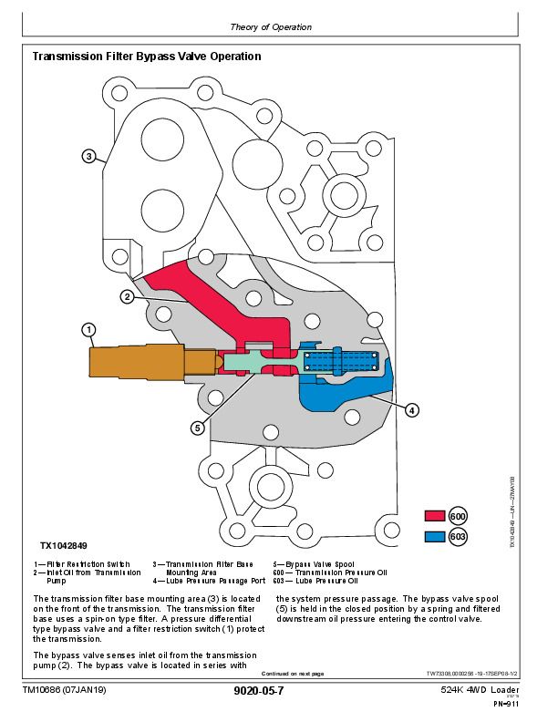
Transmission Filter Bypass Valve Operation.....911
Transmission Control Valve Component Operation.....912
Transmission Clutch Modulation Operation.....915
Thermal Bypass Valve Operation.....916
Standard Differential Operation.....918
Differential Lock Operation.....919
Rear Axle Disconnect Operation.....920
Axle Circulation Dual Pump Operation—If Equipped.....921
Park Brake Operation.....922
Diagnostic Information.....925
Transmission System Schematic—First Forward.....925
Transmission Control System.....929
Power Train Component Location.....931
Transmission Clutch Slippage.....933
Transmission Clutch Slippage Diagnostic Procedure.....933
Machine Will Not Move in Either Direction.....935
Machine Will Not Move in Either Direction Diagnostic Procedure.....935
Machine Will Not Shift Correctly.....938
Machine Will Not Shift Correctly Diagnostic Procedure.....938
Transmission System Pressure Is Low in Neutral.....941
Transmission System Pressure Is Low in Neutral Diagnostic Procedure.....941
Transmission Pressure Is Low (One or Two Gear Ranges).....942
Transmission Pressure Is Low (One or Two Gear Ranges) Diagnostic Procedure.....942
Transmission Shifts Too Slow.....943
Transmission Shifts Too Slow Diagnostic Procedure.....943
Transmission Shifts Too Fast.....945
Transmission Shifts Too Fast Diagnostic Procedure.....945
Machine Creeps in Neutral.....946
Machine Creeps in Neutral Diagnostic Procedure.....947
Transmission Hydraulic System Overheats.....948
Transmission Hydraulic System Overheats Diagnostic Procedure.....948
Transmission Excessive Noise.....950
Transmission Excessive Noise Diagnostic Procedure.....950
Rear Axle Disconnect Does Not Disengage (2WD state).....951
Rear Axle Disconnect Does Not Disengage (2WD state) Diagnostic Procedure.....952
Rear Axle Disconnect Does Not Engage (4WD state).....953
Rear Axle Disconnect Does Not Engage (4WD state) Diagnostic Procedure.....954
Oil Aerated.....955
Oil Aerated Diagnostic Procedure.....955
Oil Ejected from Filler Tube.....956
Oil Ejected from Filler Tube Diagnostic Procedure.....956
Machine Vibrates.....956
Machine Vibrates Diagnostic Procedure.....956
Machine Power and Acceleration Low.....957
Machine Power and Acceleration Low Diagnostic Procedure.....957
Torque Converter Stall RPM.....958
Torque Converter Stall RPM Diagnostic Procedure.....958
Differential Lock Will Not Engage.....960
Differential Lock Will Not Engage Diagnostic Procedure.....960
Differential Lock Slips and Chatters.....960
Differential Lock Slips and Chatters Diagnostic Procedure.....961
Differential Lock Will Not Disengage.....961
Differential Lock Will Not Disengage Diagnostic Procedure.....961
Differential Oil Level Rises.....962
Differential Oil Level Rises Diagnostic Procedure.....962
Differential Oil Level Low.....963
Differential Oil Level Low Diagnostic Procedure.....963
Differential and Axle Noise Excessive.....963
Differential and Axle Noise Excessive Diagnostic Procedure.....963
Axle Wheel Hub Face Seal Leaking.....965
Axle Wheel Hub Face Seal Leaking Diagnostic Procedure.....965
Axle Overheats.....965
Axle Overheats Diagnostic Procedure.....965
Service Brakes Poor or Do Not Apply.....966
Service Brakes Poor or Do Not Apply Diagnostic Procedure.....966
Service Brakes Aggressive.....967
Service Brakes Aggressive Diagnostic Procedure.....967
Service Brakes Dragging.....968
Service Brakes Dragging Diagnostic Procedure.....968
Service Brakes Lock Up.....969
Service Brakes Lock Up Diagnostic Procedure.....969
Service Brakes Chatter.....970
Service Brakes Chatter Diagnostic Procedure.....970
Service Brake Warning Light On.....971
Service Brake Warning Light On Diagnostic Procedure.....971
Driveline Excessive Vibration or Noise.....973
Driveline Excessive Vibration or Noise Diagnostic Procedure.....973
Park Brake Will Not Hold.....974
Park Brake Will Not Hold Diagnostic Procedure.....974
Park Brake Will Not Release.....976
Park Brake Will Not Release Diagnostic Procedure.....976
Park Brake Overheats.....977
Park Brake Overheats Diagnostic Procedure.....977
Park Brake Light Flashes When Shifting From Forward to Reverse.....978
Park Brake Light Flashes When Shifting From Forward to Reverse Diagnostic Procedure.....978
Park Brake Light Flashes During Each Shift.....979
Park Brake Light Flashes During Each Shift Diagnostic Procedure.....979
Park Brake Light Does Not Come On.....980
Park Brake Light Does Not Come On Diagnostic Procedure.....980
Park Brake Will Not Apply.....981
Park Brake Will Not Apply Diagnostic Procedure.....981
Adjustments.....983
Service Brake Bleeding Procedure.....983
External Service Brake Inspection.....984
Transmission Control Unit (TCU)—Electronic Clutch Calibration.....986
Tests.....987
Transmission Oil Sampling Procedure.....987
Transmission Oil Warmup Procedure.....987
Park Brake Pressure Test.....988
Park Brake Drag Test.....989
Transmission Pump Flow Test.....991
Transmission System Pressure Test.....992
Transmission Clutch Pressure Test.....994
Transmission Element Leakage Test.....996
Transmission Lube Pressure Test.....998
Differential Lock Pressure Test.....1000
Torque Converter—In Pressure Test.....1002
Torque Converter—Out Pressure Test.....1003
Torque Converter Relief Pressure Test.....1004
Torque Converter—Out Flow Test.....1006
Torque Converter Stall Speed Test.....1008
Transmission Oil Cooler Thermal Bypass Valve Temperature Test.....1010
Transmission Oil Cooler Thermal Bypass Valve Pressure Test.....1012
Transmission Oil Cooler Restriction Test.....1013
Axle Circulation Pump Flow Test.....1015
Axle Breather Test.....1016
Hydraulic System.....1019
Theory of Operation.....1021
Loader Hydraulic System Operation.....1021
Main Hydraulic Pump Operation.....1022
Hydraulic Pump Manifold Operation.....1026
Hydraulic Fan Operation.....1028
Hydraulic Reversing Fan Operation—If Equipped.....1030
Orbital Steering System Component Operation.....1032
Orbital Steering Valve Operation.....1033
Secondary Steering System Operation—If Equipped.....1034
Secondary Steering Valve Operation—If Equipped.....1035
Pilot Pressure Reducing Valve Operation.....1036
Service Brake Hydraulic System Operation.....1037
Service Brake Accumulator Operation.....1038
Service Brake Valve Operation.....1040
Pin Disconnect Operation.....1042
Pilot Control Lever Operation.....1044
Control Valve Pilot Orifice Check Valve Operation.....1045
Loader Control Valve Operation.....1046
Boom Section Operation—Boom Down and Steering.....1047
Bucket Section Operation—Boom Raise and Bucket Dump.....1049
Bucket Section Operation—Boom Raise and Bucket Dump (High-Lift Option).....1051
Auxiliary Section—Operating and Boom Raise.....1053
Auxiliary Section—Spool Stroke Adjuster Operation.....1055
Loader Control Valve—Outlet Section Operation.....1056
Load Sense Circuit Operation—Neutral.....1058
Load Sense Circuit Operation—Steering.....1059
Load Sense Circuit Operation—Steering and Boom Down.....1060
Load Sense Circuit Operation—Boom Raise and Bucket Dump.....1062
Main Relief Valve Operation.....1063
Load Sense Relief Valve Operation.....1065
Circuit Relief With Anticavitation Valve Operation.....1066
Anticavitation Valve Operation.....1070
Hydraulic Return Filter Operation.....1071
Ride Control Operation—If Equipped.....1073
Diagnostic Information.....1077
Hydraulic System Schematic.....1077
Hydraulic System Component Location.....1085
No Hydraulic Functions.....1111
No Hydraulic Functions Diagnostic Procedure.....1111
Hydraulic Functions Slow.....1111
Hydraulic Functions Slow Diagnostic Procedure.....1112
Main Hydraulic Pump Noisy.....1114
Main Hydraulic Pump Noisy Diagnostic Procedure.....1114
No Orbital Steering Function.....1115
No Orbital Steering Function Diagnostic Procedure.....1115
Boom Float Function Not Working.....1116
Boom Float Function Not Working Diagnostic Procedure.....1116
One Hydraulic Function Not Working.....1117
One Hydraulic Function Not Working Diagnostic Procedure.....1117
Hydraulic Function Drifts Down.....1119
Hydraulic Function Drifts Down Diagnostic Procedure.....1119
Boom Down Does Not Work (Engine Off).....1120
Boom Down Does Not Work (Engine Off) Diagnostic Procedure.....1120
Ride Control Not Working.....1121
Ride Control Not Working Procedure.....1121
Oil Overheats.....1121
Oil Overheats Diagnostic Procedure.....1121
Hydraulic Oil Foams.....1123
Hydraulic Oil Foams Diagnostic Procedure.....1123
Pin Disconnect Cylinders Will Not Retract—If Equipped.....1124
Pin Disconnect Cylinders Will Not Retract Diagnostic Procedure.....1124
Constant Steering Required to Maintain Straight Travel.....1124
Constant Steering Required to Maintain Straight Travel Diagnostic Procedure.....1124
Slow Steering Wheel Movement Will Not Cause Frame Movement.....1125
Slow Steering Wheel Movement Will Not Cause Frame Movement Diagnostic Procedure.....1125
Steering Wheel Turns Without Resistance and Causes No Frame Movement.....1125
Steering Wheel Turns Without Resistance and Causes No Frame Movement Diagnostic Procedure.....1125
Steering Erratic.....1126
Steering Erratic Diagnostic Procedure.....1126
Steering Wheel Free Play.....1126
Steering Wheel Free Play Diagnostic Procedure.....1127
Orbital Steering Valve Binds or Locks Up.....1127
Orbital Steering Valve Binds or Locks Up Diagnostic Procedure.....1127
Steering Wheel Turns by Itself.....1127
Steering Wheel Turns by Itself Diagnostic Procedure.....1127
Machine Turns in Opposite Direction as Steering Wheel.....1128
Machine Turns in Opposite Direction as Steering Wheel Diagnostic Procedure.....1128
Steering Wheel Kickback.....1128
Steering Wheel Kickback Diagnostic Procedure.....1128
Orbital Steering Jerky.....1128
Orbital Steering Jerky Diagnostic Procedure.....1128
Secondary Steering Motor Will Not Operate—If Equipped.....1129
Secondary Steering Motor Will Not Operate Diagnostic Procedure.....1129
Secondary Steering Pump Runs But Will Not Steer Machine—If Equipped.....1129
Secondary Steering Pump Runs But Will Not Steer Machine Diagnostic Procedure.....1129
Hydraulic Fan Does Not Reach Full Speed.....1130
Hydraulic Fan Does Not Reach Full Speed Diagnostic Procedure.....1130
Hydraulic Fan Runs at Full Speed Only.....1131
Hydraulic Fan Runs at Full Speed Only Diagnostic Procedure.....1131
Hydraulic Fan Does Not Spin.....1132
Hydraulic Fan Does Not Spin Diagnostic Procedure.....1132
Hydraulic Fan Will Not Reverse Direction—If Equipped.....1133
Hydraulic Fan Will Not Reverse Direction Diagnostic Procedure.....1133
Adjustments.....1135
Hydraulic Oil Cleanup Procedure Using Portable Filter Caddy.....1135
Pilot Control Lever Adjustment.....1135
Auxiliary Pilot Control Lever Adjustment.....1135
Ride Control Accumulator Gas Charge Procedure.....1136
Ride Control Accumulator Draining Procedure.....1137
Auxiliary Valve Section—Stroke Adjustment.....1138
Test.....1141
Hydraulic Oil Sampling Procedure.....1141
Hydraulic Oil Warmup Procedure.....1141
Hydraulic System Pressure and Accumulators Discharge.....1142
JT02156A Digital Pressure and Temperature Analyzer Kit Installation.....1143
Hydraulic System Operating and Standby Pressure Test.....1144
Main Hydraulic Pump Control Valve Test and Adjustment.....1146
Load Sense Relief Valve Pressure Test and Adjustment.....1152
Main Hydraulic Pump Flow Test.....1156
Main Hydraulic Pump Case Drain Test.....1160
Main Relief Valve Pressure Test.....1163
Circuit Relief With Anticavitation Valve Pressure Test.....1167
Loader Cylinder Drift Test.....1169
Boom, Bucket, and Steering Cylinder Leakage Test.....1170
Hydraulic Oil Cooler Restriction Test.....1171
Steering Cylinder Drift Test.....1173
Secondary Steering Pump Pressure Relief Valve Test—If Equipped.....1176
Secondary Steering Valve—Hydraulic System Isolation Check Valve Leakage Test—If Equipped.....1178
Secondary Steering Valve—Secondary Steering Pump Isolation Check Valve Leakage Test—If Equipped.....1181
Pilot Control Valve Pressure Test.....1183
Auxiliary Pilot Control Valve Pressure Test.....1187
Pilot Pressure Reducing Valve Pressure Test.....1190
Pilot Accumulator Gas Precharge Test.....1192
Cycle Time Test.....1194
Service Brake Accumulator Gas Precharge and Low Brake Pressure Warning Test.....1195
Service Brake Valve Pressure Test.....1197
Service Brake Valve Leakage Test.....1199
Service Brake Accumulator Inlet Check Valve Leakage Test.....1200
Pin Disconnect Pressure Test—If Equipped.....1200
Hydraulic Fan Pump Pressure Test.....1203
Hydraulic Fan Motor Speed Test.....1205
Hydraulic Fan Pump Flow Test.....1207
Hydraulic Fan Motor Case Drain Test.....1209
Hydraulic Reversing Fan Test—If Equipped.....1211
Hydraulic Oil Filter Inspection Procedure.....1211
Heating and Air Conditioning.....1213
Theory of Operation.....1215
Air Conditioning System Cycle of Operation.....1215
Diagnostic Information.....1217
Air Conditioner and Heater Component Location.....1217
Air Conditioning System Does Not Operate.....1219
Air Conditioning System Does Not Operate Diagnostic Procedure.....1219
Air Conditioner Does Not Cool Interior of Cab.....1221
Air Conditioner Does Not Cool Interior of Cab Diagnostic Procedure.....1222
Air Conditioner Runs Constantly, Too Cold.....1223
Air Conditioner Runs Constantly, Too Cold Diagnostic Procedure.....1223
Heating System Does Not Operate.....1224
Heating System Does Not Operate Diagnostic Procedure.....1224
Heater Does Not Warm Interior of Cab.....1225
Heater Does Not Warm Interior of Cab Diagnostic Procedure.....1225
Interior Windows Continue to Fog.....1226
Interior Windows Continue to Fog Diagnostic Procedure.....1226
Tests.....1227
Refrigerant Cautions and Proper Handling.....1227
R134a Refrigerant Cautions.....1227
R134a Oil Charge Capacity.....1228
R134a Refrigerant Charge Capacity.....1228
Refrigerant Hoses and Tubing Inspection.....1228
R134a Air Conditioning System Test.....1229
Operating Pressure Diagnostic Chart.....1230
Air Conditioning High/Low Pressure Switch Test.....1231
Freeze Control Switch Test.....1232
Refrigerant Leak Testing.....1232
John Deere 524K 4WD Loader Operation & Test Technical Manual (TM10686)


