John Deere 624H Loader and TC62H Tool Carrier Operation & Test Technical Manual (TM1639)
Catalog:
Model:
John Deere 624H Loader and TC62H Tool Carrier Operation & Test Technical Manual (TM1639)
TM1639 - 624H Loader and TC62H Tool Carrier Operation and Test Technical Manual.pdf
1,208 pages, bookmarked, Searchable, Printable, high quality PDF
Complete technical Operation & Test Manual with electrical wiring diagrams for John Deere 624H Loader and TC62H Tool Carrier. It's the same service manual used by dealers that guaranteed to be fully functional and intact without any missing page.
John Deere 624H Loader and TC62H Tool Carrier Operation & Test Technical Manual (including maintenance, overhaul, disassembling & assembling, adjustment, tune-up, operation, inspecting, diagnostic & troubleshooting…) is divided into different sections. Each section covers a specific component or system with detailed illustrations. A table of contents is placed at the beginning of each section. Pages are easily found by category, and each page is expandable for great detail. The printer-ready PDF documents work like a charm on all kinds of devices.
TABLE OF CONTENTS
Table of Contents
9000 - General Information . . . . 13
01 - Safety . . . . . 13
Avoid Harmful Asbestos Dust . . . 13
Avoid Heating Near Pressurized Fluid Lines . . . 14
Avoid High-Pressure Fluids . . . . 15
Dispose of Waste Properly . . . . 16
Handle Chemical Products Safely . . . 17
Handle Fluids Safely—Avoid Fires . . . 18
Keep ROPS Installed Properly . . . 19
Live With Safety . . . . 20
Park Machine Safely . . . . 21
Practice Safe Maintenance . . . . 22
Prepare for Emergencies . . . . 24
Prevent Acid Burns . . . . 25
Prevent Battery Explosions . . . . 27
Remove Paint Before Welding or Heating . . . 28
Replace Safety Signs . . . . 29
Service Machines Safely . . . . 30
Service Tires Safely . . . . 31
Support Machine Properly . . . . 33
Use Proper Lifting Equipment . . . 34
Use Proper Tools . . . . 35
Wear Protective Clothing . . . . 36
Work in Clean Area . . . . 37
Work In Ventilated Area . . . . 38
02 - General Specifications . . . . 40
624H High Lift Specifications . . . . 40
624H_TC62H Specifications . . . . 41
Drain and Refill Capacities—624H_TC62H . . . 42
Other Information—624H_TC62H . . . 43
03 - Torque Values . . . . 45
Additional Metric Cap Screw Torque Values . . . 45
Check Oil Lines And Fittings . . . . 47
Hardware Torque Specifications . . . 48
Keep ROPS Installed Properly . . . 49
Metric Bolt and Screw Torque Values . . . 50
Service Recommendations For Flat Face O-Ring Seal Fittings . . . 52
Service Recommendations For Inch Series Four Bolt Flange Fittings . . . 54
Service Recommendations for Metric Series Four Bolt Flange Fitting . . . 55
Service Recommendations for O-Ring Boss Fittings . . . 56
Unified Inch Bolt and Screw Torque Values . . . 59
04 - Fuels and Lubricants . . . . 61
Alternative and Synthetic Lubricants . . . 61Diesel Engine Oil . . . . 62
Diesel Fuel Storage . . . . 64
Diesel Fuel . . . . . 65
Fuel Tank . . . . . 66
Grease . . . . . 67
Low Sulfur Diesel Fuel Conditioner . . . 68
Lubricant Storage . . . . 69
Lubricity of Diesel Fuel . . . . 70
Mixing of Lubricants . . . . 71
Transmission, Hydraulic System, Park Brake, And Differential Oil . . . 72
9005 - Operational Checkout . . . . 73
Complete Machine Operational Checkout . . . 73
9010 - Engine . . . . . 145
05 - Theory of Operation . . . . 145
Engine—Sectional View . . . . 145
General Engine Description . . . . 146
PowerTech 4.5 L (4045) and 6.8 L (6068) John Deere Engines—Use 147 CTM104 and CTM207
15 - Diagnostic Information . . . . 148
Diagnose Engine Malfunctions . . . 148
PowerTech 4.5 L (4045) and 6.8 L (6068) John Deere Engines—Use 156
CTM 104 and CTM207
20 - Adjustments . . . . . 157
Adjust Fuel Shut-Off Solenoid . . . 157
Check And Adjust Slow and Fast Idle . . . 158
Display Monitor Tachometer . . . . 160
Monitor Display Unit-User Diagnostics Menu-Engine Sensors (d04) . . . 161
PowerTech 4.5 L (4045) and 6.8 L (6068) John Deere Engine—Use CTM104 and CTM207
Speed Control Linkage Adjustment . . . 163
25 - Tests . . . . . 165
Air Intake System Leakage Test . . . 165
Display Monitor Tachometer . . . . 167
Engine Air Heater Test Above 10°C (50°F) . . . 168
Engine Power Test Using Engine Pulldown . . . 170
Engine Power Test Using Turbocharger Boost Pressure . . . 172
Fuel Line Leakage Test . . . . 174
Injection Pump Timing . . . . 175
Monitor Display Unit-User Diagnostics Menu-Engine Sensors (d04) . . . 176
PowerTech 4.5 L (4045) and 6.8 L (6068) John Deere Engine—Use CTM104 and CTM207
9015 - Electrical System . . . . 178
05 - Theory of Operation . . . . 178
Electrical Circuit Malfunctions . . . 178
Electrical Schematic Symbols . . . 179
Electrical System Visual Inspection . . . 181Grounded Circuit . . . . 182
High Resistance Circuit . . . . 184
Multimeter . . . . . 185
Open Circuit . . . . . 186
Reading a Component Location Diagram . . . 187
Reading a Connector End View Diagram . . . 188
Reading a System Functional Schematic . . . 189
Reading a Wiring Diagram . . . . 190
Schematic, Wiring Diagram, and Component Location Information . . . 191
Sensor Circuit Shorted to Ground . . . 192
Sensor Circuit Shorted to Itself . . . 193
Sensor Circuit Shorted to Power . . . 195
Seven Step Electrical Test Procedure . . . 197
Shorted Circuit . . . . 199
10 - System Diagrams . . . . 201
Axle Disconnect Harness (W33) Component Location . . . 201
Battery (Cables) Harness (W24) Component Location . . . 202
Cab Work Lights Harness (W19) Component Location . . . 203
CAN Terminator Harness (W14) Component Location . . . 204
Component Identification Table . . . 205
Converter And Power Plug Harness (W21) Component Location . . . 207
Converter And Power Plug Harness (W21) Connectors, Wire And Pin Location
Electric Air Adjust Seat Harness (W36) Component Location . . . 209
Engine Air Heater Harness (W7) Component Location . . . 210
Engine Frame Harness (W5) Component Location . . . 211
Engine Harness (W6) And Engine Oil Pressure Switch Harness (W18) Component Location
Front Console Harness (W4) Component Location . . . 213
Functional Schematic And Component Location Legend . . . 214
Fuse (Blade-Type) Color Codes . . . 220
Fuse Specifications . . . . 221
License Plate Light Harness (W15) Component Location . . . 222
Load Center Harness (W3) Component Location . . . 223
Load Center Harness (W3) Connectors, Wire And Pin Location . . . 224
Loader Frame Harness (With Tool Carrier) (W11) Component Location
Loader Frame Harness (Without Tool Carrier) (W2) Component Location
Pin Disconnect Harness (W16) Component Location . . . 227
Radio Harness (W34) Component Location (S.N. 572399—578900) . . . 228
Radio Harness (W34) Component Location (S.N. 578901—) . . . 229
Radio Harness (W34) Component Location (S.N. —572398) . . . 230
Rear Frame Harness (W13) Component Location . . . 231
Return-to-Dig Harness (With Tool Carrier) (W12) Component
LocationReturn-to-Dig Harness (Without Tool Carrier) (W8) Component Location
Ride Control Harness (W9) Component Location . . . 234
Secondary Steering Pump Motor Harness (W23) Component Location
Secondary Steering Switch Harness (W17) Component Location . . . 236
Sump Tank Harness (W31) Component Location . . . 237
System Functional Schematic Section Legend . . . 238
System Functional Schematic . . . 239
Transmission Harness (W10) Component Location . . . 242
15 - Sub-System Diagnostics . . . . 245
Back-Up Alarm And Park Brake Sensing And Park Brake Release
Circuit Specifications
Back-Up Alarm And Park Brake Sensing And Park Brake Release
Circuit Theory Of Operation
Brake And Light Circuit Functional Schematic . . . 248
Brake And Light Circuit Operational Information . . . 249
Brake And Light Circuit Specifications . . . 250
Brake And Light Circuit Theory Of Operation . . . 251
Cab Work Light Circuit Functional Schematic . . . 252
Cab Work Light Circuit Operational Information . . . 253
Cab Work Light Circuit Theory Of Operation . . . 254
Charging Circuit Functional Schematic . . . 255
Charging Circuit Operational Information . . . 256
Charging Circuit Theory Of Operation . . . 257
Chassis Computer Unit Circuit Connector Signals For 30—Pin Connector
Chassis Computer Unit Circuit Connector Signals For 60—Pin Connector
Chassis Computer Unit Circuit Functional Schematic . . . 263
Chassis Computer Unit Circuit Operational Information . . . 264
Chassis Computer Unit Circuit Theory Of Operation . . . 265
Chassis Computer Unit—Battery Monitoring Signals . . . 266
Chassis Computer Unit—Drive Lights And Work Lights Signals . . . 267
Chassis Computer Unit—Intermittent Wipers Circuit Signals . . . 268
Chassis Computer Unit—Tail_Marker Lights Signals . . . 269
Chassis Computer Unit—Turn And Flasher Light Signals . . . 270
Converter And Radio Circuit Functional Schematic . . . 271
Differential Lock, Pin Disconnect, And Axle Disconnect Circuit Functional Schematic
Drive Light Circuit Functional Schematic . . . 273
Drive Light Circuit Theory Of Operation . . . 274
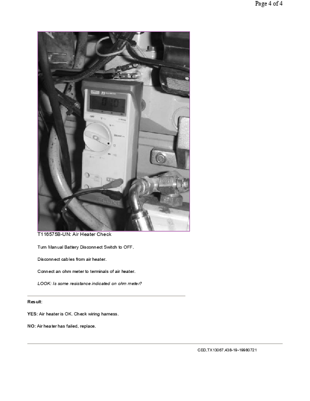
Engine Air Heater Circuit Diagnostic Procedures . . . 275
Engine Air Heater Circuit Functional Schematic . . . 279
Engine Air Heater Circuit Operation . . . 280
Engine Air Heater Circuit Operational Information . . . 281Flasher And Turn Signal Functional Schematic . . . 282
Front Wiper Circuit Functional Schematic . . . 283
Fuel Shutoff Circuit Functional Schematic . . . 284
Fuel Shutoff Circuit Operational Information . . . 285
Fuel Shutoff Circuit Theory Of Operation . . . 286
Horn Circuit Functional Schematic . . . 287
Monitor Display Unit Circuit Functional Schematic . . . 288
Monitor Display Unit Circuit Operational Information . . . 289
Monitor Display Unit Circuit Specifications—Gauge Ranges . . . 290
Monitor Display Unit Circuit Specifications—Switches And Senders . . . 292
Monitor Display Unit Circuit Theory Of Operation—Caution And Warning Lights And Gauges
Monitor Display Unit Circuit Theory Of Operation—Function . . . 295
Monitor Display Unit Circuit Theory Of Operation—Modes Of Operation
Monitor Display Unit Circuit Theory Of Operation—Switches, Sensors And Indicator Lights 297
Monitor Display Unit Gauge Sensor Specifications and Diagnostic Display 301
Monitor Display Unit Menu Structure . . . 303
Monitor Display Unit Reconfiguration—Access Service Menu . . . 304
Monitor Display Unit Reconfiguration—Delete Service Codes . . . 305
Monitor Display Unit Reconfiguration—Enable Options (S 06) . . . 306
Monitor Display Unit Reconfiguration—Machine Model (S 01) . . . 307
Monitor Display Unit Reconfiguration—Tire Size (S 03) . . . 308
Monitor Display Unit-Diagnostics Menu-Engine Sensors (d 04) . . . 309
Monitor Display Unit—Accessing Menus . . . 311
Monitor Display Unit—Accessory Menu—0.1 Hour Meter Mode (A 06) . . 312
Monitor Display Unit—Accessory Menu—Auto Mode To First (A 03) . . . 313
Monitor Display Unit—Accessory Menu—Clutch Cutoff (A 01) . . . 314
Monitor Display Unit—Accessory Menu—Job Timer Mode (A 04) . . . 316
Monitor Display Unit—Accessory Menu—Metric Units Mode (A 07) . . . 317
Monitor Display Unit—Accessory Menu—Quick Shift Mode (A 02) . . . 318
Monitor Display Unit—Accessory Menu—Stop Watch Mode (A 05) . . . 320
Monitor Display Unit—Diagnostics Menu—Battery Monitor (d 03) . . . 321
Monitor Display Unit—Diagnostics Menu—Continuity Check (d 02) . . . 322
Monitor Display Unit—Diagnostics Menu—Fuel Sensor (d 07) . . . 325
Monitor Display Unit—Diagnostics Menu—Functional Service Codes
...


