John Deere 644J Loader Repair Technical Manual (TM10246)
Catalog:
Model:
Complete Repair Technical Manual for John Deere 644J Loader. It's the same service manual used by dealers that guaranteed to be fully functional and intact without any missing page.
John Deere 644J Loader Repair Technical Manual (including maintenance, overhaul, disassembling & assembling, adjustment, tune-up, operation, inspecting, diagnostic & troubleshooting…) is divided into different sections. Each section covers a specific component or system with detailed illustrations. A table of contents is placed at the beginning of each section. Pages are easily found by category, and each page is expandable for great detail. The printer-ready PDF documents work like a charm on all kinds of devices.
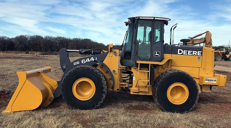
TM10246 - John Deere 644J Loader (S.N. 611232— ) Technical Manual (Repair).pdf
668 pages, bookmarked, Searchable, Printable, high quality PDF
CONTENTS
00 - General Information
01 - Tracks
02 - Axles and Suspension Systems
03 - Transmission
04 - Engine
05 - Engine Auxiliary Systems
07 - Dampener Drive
09 - Steering System
10 - Service Brakes
11 - Park Brake
17 - Frames, Chassis, or Supporting Structure
18 - Operator's Station
19 - Sheet Metal and Styling
31 - Loader
9900 - Dealer Fabricated Tools
...
tm10246 - 644J Loader (611232- )
Table of Contents
Foreword
Technical Information Feedback Form
Section 00: General Information
Group 0001: Safety Information
Recognize Safety Information
Follow Safety Instructions
Operate Only If Qualified
Wear Protective Equipment
Avoid Unauthorized Machine Modifications
Add Cab Guarding For Special Uses
Inspect Machine
Stay Clear of Moving Parts
Avoid High-Pressure Fluids
Avoid High-Pressure Oils
Beware of Exhaust Fumes
Prevent Fires
Prevent Battery Explosions
Handle Chemical Products Safely
Dispose of Waste Properly
Prepare for Emergencies
Use Steps and Handholds Correctly
Start Only From Operator's Seat
Use and Maintain Seat Belt
Prevent Unintended Machine Movement
Avoid Work Site Hazards
Use Special Care When Operating Loader
Keep Riders Off Machine
Avoid Backover Accidents
Avoid Machine Tip Over
Operating on Slopes
Operating or Traveling On Public Roads
Inspect and Maintain ROPS
Add and Operate Attachments Safely
Park And Prepare For Service Safely
Service Cooling System Safely
Remove Paint Before Welding or Heating
Make Welding Repairs Safely
Drive Metal Pins Safely
Group 0003: Torque Values
Metric Bolt and Cap Screw Torque Values
Additional Metric Cap Screw Torque Values
Unified Inch Bolt and Cap Screw Torque Values
Service Recommendations for 37° Flare and 30° Cone Seat Connectors
Service Recommendations for O-Ring Boss Fittings
O-Ring Boss Fittings in Aluminum Housing Service Recommendations—Excavators
Service Recommendations for Flared Connections—Straight or Tapered Threads
Service Recommendations for Flat Face O-Ring Seal Fittings
O-Ring Face Seal Fittings With SAE Inch Hex Nut and Stud End for High-Pressure Service Recommendations
O-Ring Face Seal Fittings With Metric Hex Nut and Stud End for Standard Pressure Service Recommendations
O-Ring Face Seal Fittings With Metric Hex Nut and Stud End for High-Pressure Service Recommendations
Service Recommendations for Metric Series Four Bolt Flange Fitting
Service Recommendations For Inch Series Four Bolt Flange Fittings
Inch Series Four Bolt Flange Fitting for High-Pressure Service Recommendations
Service Recommendations For Non-Restricted Banjo (Adjustable) Fittings
Service Recommendations For O-Ring Boss Fittings With Shoulder
Metric 24° O-Ring Seal DIN 20078 Service Recommendations
Section 01: Wheels
Group 0110: Powered Wheels And Fasteners
Wheel Remove and Install
Tire Remove and Install
Section 02: Axles And Suspension Systems
Group 0200: Removal And Installation
TeamMate™ IV Axles
Front Axle and Differential Remove and Install
Rear Axle and Differential Remove and Install
Axle Oscillating Supports Disassemble and Assemble
Group 0225: Input Drive Shafts and U-Joints
Universal Joint and Drive Shaft Remove and Install
Universal Joint and Drive Shaft Disassemble and Assemble
Group 0250: Axle Shaft, Bearings, and Reduction Gears
TeamMate™ IV Axles
Group 0260: Hydraulic System
Differential Lock Solenoid Valve Remove and Install
Axle Circulation System
Axle Oil Coolers Disassemble and Assemble
Section 03: Transmission
Group 0300: Removal And Installation
Transmission Remove and Install
Group 0350: Gears, Shafts, Bearings and Power Shift Clutch
Torque Converter And Housing Remove
Torque Converter and Housing Install
Clutches, Input and Output Shafts Remove
Clutches, Input and Output Shafts Install
Clutch Pack KV and KR Disassemble
Clutch Pack KV and KR Assemble
Input Shaft Disassemble
Input Shaft Assemble
Group 0360: Hydraulic System
Transmission Pump Remove and Install
Converter Minimum Pressure Regulator Valve Remove and Install
Transmission Control Valve Remove and Install
Transmission Control Valve Disassemble and Assemble
Converter Relief Valve Repair
Transmission Internal Oil Pipes and Tubes Remove and Install
Section 04: Engine
Group 0400: Removal and Installation
PowerTech Plus POWERTECH is a trademark of Deere & Company 4.5 L (4045) and 6.8 L (6068) John Deere Engines
Engine Remove and Install
Engine Crankshaft Dampener Remove and Install
Section 05: Engine Auxiliary Systems
Group 0505: Cold Weather Starting Aids
Engine Coolant Heater Remove and Install
Group 0510: Cooling System
Serpentine Belt Remove and Install
Fan and Fan Drive Motor Remove and Install
Fan Drive and Axle Circulation Pump Remove and Install
Intercooler Remove and Install
Radiator Remove and Install
Hydraulic Oil Cooler Remove and Install
Transmission Oil Cooler Remove and Install
Cooling Package Plenum Remove and Install
Group 0520: Intake System
Air Cleaner Remove and Install
Group 0530: External Exhaust System
Muffler Remove and Install
Group 0560: External Fuel Supply Systems
Fuel Tank Remove and Install
Section 07: Dampener Drive
Group 0752: Elements
Output Dampener Remove and Install
Section 09: Steering System
Group 0960: Hydraulic System
Steering Valve Remove and Install
Steering Column Remove and Install
Steering Column Disassemble and Assemble
Steering Cylinder Remove and Install (S.N. —618143)
Steering Cylinder Remove and Install (S.N. 618144— )
Steering Cylinder Bushings Remove and Install (S.N. —618143)
Steering Cylinder Bushings Remove and Install (S.N 618144— )
Section 10: Service Brakes
Group 1011: Active Elements
Brake Pedal and Linkage Disassemble and Assemble
Brake Assembly Remove And Install
Group 1060: Hydraulic System
Brake Valve Remove and Install
Brake Accumulator Remove and Install
Section 11: Park Brake
Group 1111: Active Elements
Park Brake Remove and Install
Park Brake Disassemble and Assemble
Group 1160: Hydraulic System
Park Brake Release Solenoid Valve Remove and Install
Park Brake Pressure Switch Remove and Install
Section 17: Frame Or Supporting Structure
Group 1740: Frame Installation
Engine and Loader Frame Separate
Remove and Install Upper Pivot Bearing and Seals
Lower Pivot Bearing and Seals Remove and Install
Group 1746: Frame Bottom Guards
Fuel Tank Guard Remove and Install
Front Axle Guard Remove and Install
Transmission Bottom Guard Remove and Install
Group 1749: Chassis Weights
Counterweights Remove and Install
Rear Counterweight Remove and Install
Section 18: Operator’s Station
Group 1800: Removal And Installation
Cab Remove
Cab Install
Group 1810: Operator Enclosure
Front Windshield Wiper Adjust
Group 1830: Heating And Air Conditioning
R134a Refrigerant Cautions
R134a Compressor Oil Charge Check
R134a Compressor Oil Removal
R134a Component Oil Charge
Leak Testing
Refrigerant Hoses and Tubing Inspection
R134a Refrigerant Recovery, Recycling and Charging Station Installation Procedure
R134a System Recover
R134a System Evacuate
R134a System Charge
Air Conditioner System Cleaning Procedures
Air Conditioner System Purge
Air Conditioner System Flush
Air Conditioning Module With Heater/Evaporator Coil
Heater/Evaporator Core Remove and Install
Expansion Valve Remove and Install
Freeze Control Switch Remove and Install
Freeze Control Switch Bench Test
Heater Control Valve Remove and Install
Heater Control Valve Leak Check
Main Blower Assembly Remove And Install
Pressurizer Motor Assembly Remove and Install
Receiver-Dryer and Condenser Remove and Install
A/C Binary Pressure Switch Remove and Install
Fresh Air Filter Remove and Install
Recirculating Air Filter Remove and Install
Compressor Remove and Install
Compressor Clutch—R134a Disassemble and Assemble
Clutch Hub Clearance—R134a Check
Compressor Manifold—R134a Inspect
Compressor—R134a Disassemble, Inspect, and Assemble
Section 19: Sheet Metal And Styling
Group 1910: Hood or Engine Enclosure
Hood Remove and Install
Engine Side Shields Remove and Install
Group 1921: Grille and Fan Housing
Grille and Fan Housing Remove and Install
Section 31: Loader
Group 3102: Bucket
Bucket Remove and Install
Welded-On Bucket Cutting Edges Remove and Install
Bolt-On Cutting Edges and Wear Plates Remove and Install
Cracked Cutting Edge Repair
Group 3140: Frames
NeverGrease™ Pin Joints
Loader Bucket Tilt Linkage Remove and Install
Bucket Linkage Seals and Bushings Remove and Install
Loader Boom Bushings and Seals Remove and Install
Boom Remove and Install
Powerllel™ Leveling Link Disassemble and Assemble
Powerllel™ Bellcrank Remove and Install
Powerllel™ Bucket Cylinder Remove and Install
Powerllel™ Bucket Link Disassemble and Assemble
Powerllel™ Guide Links Remove and Install
Powerllel™ Coupler Disassemble and Assemble
Powerllel™ Loader Boom Disassemble and Assemble
Hi-Vis Coupler Disassemble and Assemble
Group 3160: Hydraulic System
Hydraulic Oil Cleanup Procedure Using Portable Filter Caddy
Hydraulic Pump Start-Up Procedure
Hydraulic Pump Remove and Install
Hydraulic Pump Disassemble and Assemble
Hydraulic Pump Control Valve Remove and Install
Hydraulic Pump Control Valve Disassemble and Assemble
Loader Control Valve Remove and Install
Loader Control Valve Disassemble and Assemble
Auxiliary Valve Section And Bucket Section Disassemble And Assemble
Boom Valve Section Disassemble And Assemble
Relief Valve Disassemble and Assemble
Bucket Circuit Relief Valve Disassemble and Assemble
Load Sense Relief Valve Disassemble and Assemble
Anti-Cavitation Relief Valve Disassemble and Assemble
Boom Cylinder Remove and Install—185 Series
Bucket Cylinder Remove and Install—185 Series
Boom Cylinder Piston Wear Ring Configuration
Loader Start-Up Procedure
Boom and Bucket Cylinder Bushings and Seals Remove and Install
Hydraulic Reservoir Remove and Install
Pilot Control Valve Remove and Install
Pilot Control Valve Disassemble and Assemble
Boom Down Accumulator Remove and Install
Pressure Reducing Valve Manifold Remove and Install
Pressure Reducing Valve Manifold Disassemble and Assemble
Ride Control Valve Remove and Install
Ride Control Valve Disassemble and Assemble
Ride Control Accumulator Remove and Install
Pin Disconnect Valve Remove and Install
Pin Disconnect Valve Disassemble and Assemble
Section 9900: Dealer Fabricated Tools
Group 0099: Dealer Fabricated Tools
DFT1132 Hydraulic Pump Removal And Installation Tool
DFT1149 Pre-Load Clutch Pack Compression Ring Tool
DFT1158 Torque Converter Adapter Plate
DFT1063 Lifting Bracket
DFRW20 Compressor Holding Fixture
John Deere 644J Loader Repair Technical Manual (TM10246)


