John Deere 700K Operation & Test Technical Manual (TM12294)
Catalog:
Model:

Complete technical Operation & Test Manual with electrical wiring diagrams for John Deere 700K. It's the same service manual used by dealers that guaranteed to be fully functional and intact without any missing page.
John Deere 700K Operation & Test Technical Manual (including maintenance, overhaul, disassembling & assembling, adjustment, tune-up, operation, inspecting, diagnostic & troubleshooting…) is divided into different sections. Each section covers a specific component or system with detailed illustrations. A table of contents is placed at the beginning of each section. Pages are easily found by category, and each page is expandable for great detail. The printer-ready PDF documents work like a charm on all kinds of devices.
TM12294 - John Deere 700K Crawler Dozer Technical Manual - Operation and Test.pdf
TM12294 - John Deere 700K Crawler Dozer Technical Manual - Operation and Test.epub
MAIN CONTENTS
9000 - General Information
9001 - Diagnostic Trouble Codes (DTCs)
9005 - Operational Checkout Procedures
9010 - Engine
9015 - Electrical System
9025 - Hydraulic System
9026 - Hydrostatic System
9031 - Heating and Air Conditioning
...
TABLE OF CONTENTS..........1
Section 9000: General Information..........21
Group 01: Safety..........21
Recognize Safety Information..........24
Follow Safety Instructions..........25
Operate Only If Qualified..........26
Wear Protective Equipment..........27
Avoid Unauthorized Machine Modifications..........28
Inspect Machine..........29
Stay Clear of Moving Parts..........30
Avoid High-Pressure Oils..........31
Work In Ventilated Area..........32
Prevent Fires..........33
Prevent Battery Explosions..........34
Handle Chemical Products Safely..........35
Decommissioning — Proper Recycling and Disposal of Fluids and Components..........36
Exhaust Filter Ash Handling and Disposal..........37
Prepare for Emergencies..........38
Add Cab Guarding for Special Uses..........39
Clean Debris from Machine..........40
Use Steps and Handholds Correctly..........41
Start Only From Operator's Seat..........42
Use and Maintain Seat Belt..........43
Prevent Unintended Machine Movement..........44
Avoid Work Site Hazards..........45
Keep Riders Off Machine..........47
Avoid Backover Accidents..........48
Avoid Machine Tip Over..........49
Inspect and Maintain ROPS..........51
Add and Operate Attachments Safely..........52
Park and Prepare for Service Safely..........53
Service Cooling System Safely..........54
Remove Paint Before Welding or Heating..........55
Make Welding Repairs Safely..........56
Drive Metal Pins Safely..........57
Clean Exhaust Filter Safely..........58
Section 9001: Diagnostic Trouble Codes (DTCs)..........61
Group 10: Engine Control Unit (ECU) Diagnostic Trouble Codes..........72
Engine Control Unit (ECU) Diagnostic Trouble Codes..........72
000091.09 - CAN Throttle Missing From VCU..........61
000111.07 - Engine Coolant Level Invalid..........61
000111.17 - Engine Coolant Temperature Invalid..........61
000647.05 - Fan Drive Solenoid Open or Short to Power..........61
000647.06 - Fan Drive Solenoid Short to Ground..........61
001321.09 - Starter Signal Missing..........61
001321.16 - Engine Starter Engaged Too Long..........61
001321.31 - Starter Solenoid Open Circuit..........61
002000.13 - Security Violation..........61
002030.19 - Communication Error With Source Address 30..........61
003353.31 - Alternator Excitation Condition Exists..........61
005484.05 - Fan Reversing Solenoid Open or Short to Power..........61
005484.06 - Fan Reversing Solenoid Short to Ground..........61
Group 20: Standard Display Monitor (SDM) Diagnostic Trouble Codes..........106
Standard Display Monitor (SDM) Diagnostic Trouble Codes..........106
000096.03 - Fuel Level Sensor Open or Short..........61
000096.04 - Fuel Level Sensor Short to Ground..........61
002000.09 - CAN Communication No ECU Configuration..........61
002030.09 - Loss of CAN Communication With VCU..........61
002141.09 - Loss of CAN Communication With SSM..........61
003156.09 - Loss of CAN Communication With EHC..........61
Group 30: Sealed Switch Module (SSM) Diagnostic Trouble Codes..........129
Sealed Switch Module (SSM) Diagnostic Trouble Codes..........129
000444.04 - Invalid Application Configuration..........61
000629.12 - JDOS Watchdog Timeout..........61
000639.12 - Lost CAN Message..........61
000639.14 - CAN Bus Off..........61
002033.09 - No CAN Messages..........61
002634.04 - Ignition Relay Short to Ground..........61
002634.05 - Ignition Relay Open Circuit..........62
520752.04 - Keypad 7 Button Stuck..........62
520752.09 - No LED Response For Keypad 7 Button..........62
520753.04 - Washer Button Stuck..........62
520753.09 - No LED Response For Washer Button..........62
520754.04 - Keypad 9 Button Stuck..........62
520754.09 - No LED Response for Keypad 9 Button..........62
520755.04 - Transmission Speed Up Button Stuck..........62
520755.09 - No LED Response For Transmission Speed Up Button..........62
523335.04 - Transmission Speed Down Button Stuck..........62
523335.09 - No LED Response For Transmission Speed Down Button..........62
523336.04 - Rear Wiper Button Stuck..........62
523336.09 - No LED Response For Rear Wiper Button..........62
523338.04 - Front Wiper Button Stuck..........62
523338.09 - No LED Response For Front Wiper Button..........62
523339.04 - Wiper Speed Button Stuck..........62
523339.09 - No LED Response For Wiper Speed Button..........62
523340.04 - Standard Lights Button Stuck..........62
523340.09 - No LED Response For Standard Lights Button..........62
523849.04 - Work Lights Button Stuck..........62
523849.09 - No LED Response For Work Lights Button..........62
523850.04 - Boom-Height Kickout Button Stuck..........62
523850.09 - No LED Response For Boom-Height Kickout Button..........62
523852.04 - Keypad 6 Button Stuck..........62
523852.09 - No LED Response For Keypad 6 Button..........62
523854.04 - Keypad 5 Button Stuck..........62
523854.09 - No LED Response For Keypad 5 Button..........62
523855.04 - Keypad 4 Button Stuck..........62
523855.09 - No LED Response For Keypad 4 Button..........62
523856.04 - Auxiliary Power Button Stuck..........62
523856.09 - No LED Response For Auxiliary Power Button..........62
523857.04 - Return To Dig Button Stuck..........62
523857.09 - No LED Response For Return To Dig Button..........62
523858.04 - Keypad 3 Button Stuck..........63
523858.09 - No LED Response For Keypad 3 Button..........63
523860.04 - Keypad 2 Button Stuck..........63
523860.09 - No LED Response For Keypad 2 Button..........63
523861.04 - Auto-Off Button Stuck..........63
523861.09 - No LED Response For Auto-Off Button..........63
523862.04 - Reversing Fan Button Stuck..........63
523862.09 - No LED Response For Reversing Fan Button..........63
523863.04 - Hydraulic Enable Button Stuck..........63
523863.09 - No LED Response For Hydraulic Enable Button..........63
523864.04 - Undefined Button 4 Stuck..........63
523864.09 - No LED Response For Undefined Button 4..........63
523865.04 - Undefined Button 3 Stuck..........63
523865.09 - No LED Response For Undefined Button 3..........63
523867.04 - Stop Button Stuck..........63
523867.09 - No LED Response For Stop Button..........63
523868.04 - Start Button Stuck..........63
523868.09 - No LED Response For Start Button..........63
Group 40: Vehicle Control Unit (VCU) Diagnostic Trouble Codes..........248
Vehicle Control Unit (VCU) Diagnostic Trouble Codes..........248
000070.00 - Park Lock Lever Inputs Both ON..........63
000070.01 - Park Lock Lever Inputs Both OFF..........63
000091.03 - Throttle Sensor Short to Power..........63
000091.04 - Throttle Sensor Open or Short..........63
000116.00 - Brake Pressure High..........63
000116.01 - Brake Pressure Low..........63
000116.03 - Brake Pressure Short to Power..........63
000116.04 - Brake Pressure Open or Short..........63
000158.03 - Switched System Volts Too High..........63
000158.04 - Switched System Volts Too Low..........63
000168.04 - Unswitched System Volts Too Low..........63
000177.00 - Trans Oil Temp Overtemp..........63
000177.03 - Trans Oil Temp Short to Power..........63
000177.04 - Trans Oil Temp Short to Ground..........64
000177.16 - Trans Oil Temp Mod Overtemp..........64
000190.09 - CAN Comm No Engine Speed..........64
000190.19 - CAN Engine Speed Message Invalid Data..........64
000521.00 - Decel Sensor Input > Max Cal..........64
000521.01 - Decel Sensor Input < Min Cal..........64
000521.03 - Decel Sensor Short to Power..........64
000521.04 - Decel Sensor Open or Short..........64
000521.05 - Decel Sensor Brake Cal Too Lo..........64
000521.06 - Decel Sensor Brake Cal Too Hi..........64
000521.13 - Decel Sensor Not Calibrated..........64
000521.15 - Decel Sensor Min Cal Too High..........64
000521.16 - Decel Sensor Max Cal Too High..........64
000521.17 - Decel Sensor Min Cal Too Low..........64
000521.18 - Decel Sensor Max Cal Too Low..........64
000581.00 - Speed Buttons Input > Max Cal..........64
000581.01 - Speed Buttons Input < Min Cal..........64
000581.03 - Speed Buttons Short to Power..........64
000581.04 - Speed Buttons Open or Short..........64
000581.07 - Speed Buttons Stuck Button..........64
000581.13 - Speed Buttons Not Calibrated..........64
000581.15 - Speed Buttons Min Cal Too High..........64
000581.16 - Speed Buttons Max Cal Too High..........64
000581.17 - Speed Buttons Min Cal Too Low..........64
000581.18 - Speed Buttons Max Cal Too Low..........64
000604.03 - FNR Neutral Switch Open Circuit..........64
000604.04 - FNR Neutral Switch Short Circuit..........64
000604.15 - FNR Neut Switch Min Cal Too High..........64
000604.16 - FNR Neut Switch Max Cal Too High..........64
000604.17 - FNR Neut Switch Min Cal Too Low..........64
000604.18 - FNR Neut Switch Max Cal Too Low..........64
000619.05 - Brake Solenoid Open or Short to Power..........64
000619.06 - Brake Solenoid Short to Ground..........64
000629.12 - VCU Watchdog Timer Exceeded..........65
000907.04 - Left Speed Sensor Short to Ground..........65
000907.07 - Left Speed Sensor No Response..........65
000907.12 - Left Speed Sensor Open..........65
000908.04 - Right Speed Sensor Short to Ground..........65
000908.07 - Right Speed Sensor No Response..........65
000908.12 - Right Speed Sensor Open..........65
000924.06 - Aux Power Short to Ground..........65
001569.31 - Engine Derate Condition..........65
001638.00 - Hyd Oil Temp Overtemp..........65
001638.03 - Hyd Oil Temp Short to Power..........65
001638.04 - Hyd Oil Temp Short to Gnd..........65
001638.16 - Hyd Oil Temp Mod Overtemp..........65
001713.31 - Hyd Oil Filter Restricted..........65
002000.09 - Loss of CAN comm with ECU..........65
002023.09 - Loss of CAN Comm with SDM..........65
002141.09 - Loss of CAN Comm with SSM..........65
002251.09 - Communication System Message Missing..........65
002355.05 - Front Work Light Open or Short to Power..........65
002355.06 - Front Work Light Short to Ground..........65
002356.05 - Front Drive Light Open or Short to Power..........65
002356.06 - Front Drive Light Short to Ground..........65
002359.05 - Rear Drive Light Open or Short to Power..........65
002359.06 - Rear Drive Light Short to Ground..........65
002660.00 - Steer Sensor Input > Max Cal..........65
002660.01 - Steer Sensor Input < Min Cal..........65
002660.03 - Steer Sensor Short to Power..........65
002660.04 - Steer Sensor Open or Short..........65
002660.07 - Steer Sensor Neut Cal Out of Range..........65
002660.13 - Steer Sensor Not Calibrated..........65
002660.15 - Steer Sensor Min Cal Too High..........65
002660.16 - Steer Sensor Max Cal Too High..........65
002660.17 - Steer Sensor Min Cal Too Low..........65
002660.18 - Steer Sensor Max Cal Too Low..........66
002661.00 - FNR Sensor Input > Max Cal..........66
002661.01 - FNR Sensor Input < Min Cal..........66
002661.03 - FNR Sensor Short to Power..........66
002661.04 - FNR Sensor Open or Short..........66
002661.07 - FNR Sensor Neut Cal Out of Range..........66
002661.13 - FNR Sensor Not Calibrated..........66
002661.15 - FNR Sensor Min Cal Too High..........66
002661.16 - FNR Sensor Max Cal Too High..........66
002661.17 - FNR Sensor Min Cal Too Low..........66
002661.18 - FNR Sensor Max Cal Too Low..........66
003359.31 - Trans Oil Filter Restricted..........66
003509.03 - 5V Supply #1 Short to Power..........66
003509.04 - 5V Supply #1 Short to Ground..........66
003511.03 - 5V Supply #3 Short to Power..........66
003511.04 - 5V Supply #3 Short to Ground..........66
003512.03 - 5V Supply #4 Short to Power..........66
003512.04 - 5V Supply #4 Short to Ground..........66
521996.05 - Door Washer Motor Open or Short to Power..........66
521996.06 - Door Washer Motor Short to Ground..........66
521997.05 - Left Door Wiper Open or Short to Power..........66
521997.06 - Left Door Wiper Short to Ground..........66
521998.05 - Right Door Wiper Open or Short to Power..........66
521998.06 - Right Door Wiper Short to Ground..........66
521999.00 - Park Lock Lever Inputs Both On..........66
521999.01 - Park Lock Lever Inputs Both Off..........66
522312.05 - Washer Motor Open or Short to Power..........66
522312.06 - Washer Motor Short to Ground..........66
522433.05 - Rear Wiper Open or Short to Power..........66
522433.06 - Rear Wiper Short to Ground..........66
522434.05 - Front Wiper Open or Short to Power..........66
522434.06 - Front Wiper Short to Ground..........66
522444.00 - Charge Pressure High..........66
522444.01 - Charge Pressure Low..........67
522444.03 - Charge Pressure Short to Power..........67
522444.04 - Charge Pressure Open or Short..........67
522447.05 - Right Fwd Pump Coil Open or Short..........67
522447.06 - Right Fwd Pump Coil Short to Power..........67
522447.15 - Right Fwd Pump Thresh Cal High..........67
522447.16 - Right Fwd Pump Max Spd Cal High..........67
522447.17 - Right Fwd Pump Thresh Cal Low..........67
522447.18 - Right Fwd Pump Max Spd Cal Low..........67
522448.05 - Right Rev Pump Coil Open or Short..........67
522448.06 - Right Rev Pump Coil Short to Pwer..........67
522448.15 - Right Rev Pump Thresh Cal High..........67
522448.16 - Right Rev Pump Max Spd Cal High..........67
522448.17 - Right Rev Pump Thresh Cal Low..........67
522448.18 - Right Rev Pump Max Spd Cal Low..........67
522449.05 - Left Rev Pump Coil Open or Short..........67
522449.06 - Left Rev Pump Coil Short to Power..........67
522449.15 - Left Rev Pump Thresh Cal High..........67
522449.16 - Left Rev Pump Max Spd Cal High..........67
522449.17 - Left Rev Pump Thresh Cal Low..........67
522449.18 - Left Rev Pump Max Spd Cal Low..........67
522450.05 - Left Fwd Pump Coil Open or Short..........67
522450.06 - Left Fwd Pump Coil Short to Power..........67
522450.15 - Left Fwd Pump Thresh Cal High..........67
522450.16 - Left Fwd Pump Max Spd Cal High..........67
522450.17 - Left Fwd Pump Thresh Cal Low..........67
522450.18 - Left Fwd Pump Max Spd Cal Low..........67
523108.13 - Pump/Motor Not Calibrated..........67
523108.14 - VCU Not Calibrated..........67
523577.05 - Left Motor Sol Open or Short..........67
523577.06 - Left Motor Sol Short to Power..........67
523577.13 - Motor High Speed Not Calibrated..........67
523577.16 - Left Motor Max Cal Too High..........67
523577.18 - Left Motor Max Cal Too Low..........68
523578.05 - Right Motor Sol Open or Short..........68
523578.06 - Right Motor Sol Short to Power..........68
523578.16 - Right Motor Max Cal Too High..........68
523578.18 - Right Motor Max Cal Too Low..........68
524233.07 - Hydrostatic Drive System Not Responding..........68
Group 50: Blade Control Joystick (BCJ) Diagnostic Trouble Codes..........632
Blade Control Joystick (BCJ) Diagnostic Trouble Codes..........632
002697.03 - X-Axis Sensor Out of Range High..........68
002697.04 - X-Axis Sensor Out of Range Low..........68
002697.12 - X-Axis Joystick Internal Failure..........68
002697.13 - X-Axis Joystick Setup Failure..........68
002697.14 - X-Axis Joystick Sensor Failure..........68
002698.03 - Y-Axis Sensor Out of Range High..........68
002698.04 - Y-Axis Sensor Out of Range Low..........68
002698.12 - Y-Axis Joystick Internal Failure..........68
002698.13 - Y-Axis Joystick Setup Failure..........68
002698.14 - Y-Axis Joystick Sensor Failure..........68
Group 60: Electrohydraulic Controller (EHC) Diagnostic Trouble Codes..........644
Electrohydraulic Controller (EHC) Diagnostic Trouble Codes..........644
000158.03 - EHC System Volts Too High..........68
000158.04 - EHC System Volts Too Low..........68
000620.03 - Sensor Short to Power..........68
000620.04 - Sensor Short to Ground..........68
001903.00 - Auxiliary 1 PVE Open Circuit..........68
001903.01 - Auxiliary 1 PVE Low or Open Circuit..........68
001903.03 - Auxiliary 1 PVE Short to Power..........68
001903.04 - Auxiliary 1 PVE Short to Ground..........68
001903.31 - Auxiliary 1 PVE Spool Position Error..........68
001915.00 - Auxiliary 2 PVE Open Circuit..........68
001915.01 - Auxiliary 2 PVE Low or Open Circuit..........68
001915.03 - Auxiliary 2 PVE Short to Power..........68
001915.04 - Auxiliary 2 PVE Short to Gound..........68
001915.31 - Auxiliary 2 PVE Spool Position Error..........69
002697.09 - CAN Joystick Position Missing From BCJ..........69
003157.03 - Increment/Decrement Buttons Short to Power..........69
003157.04 - Increment/Decrement Buttons Open or Short..........69
003157.31 - Increment/Decrement Buttons Invalid Output..........69
522442.03 - Blade Button Short to Power..........69
522442.04 - Blade Buttons Open or Short..........69
522442.31 - Blade Buttons Invalid Output..........69
523779.00 - Blade Rotate Current Above Maximum..........69
523779.01 - Blade Rotate Current Below Minimum..........69
523780.00 - Tilt PVE Open Circuit..........69
523780.01 - Tilt PVE Low or Open Circuit..........69
523780.03 - Tilt PVE Short to Power..........69
523780.04 - Tilt PVE Short to Ground..........69
523780.31 - Tilt PVE Spool Position Error..........69
523781.00 - Height PVE Open Circuit..........69
523781.01 - Height PVE Low or Open Circuit..........69
523781.03 - Height PVE Short to Power..........69
523781.04 - Height PVE Short to Ground..........69
523781.31 - Height PVE Spool Position Error..........69
524059.00 - Auxiliary 2 Joystick Sensor 2 Volts High..........69
524059.01 - Auxiliary 2 Joystick Sensor 2 Volts Low..........69
524059.03 - Auxiliary 2 Joystick Sensor 2 Short to Power..........69
524059.04 - Auxiliary 2 Joystick Sensor 2 Short to Ground..........69
524059.31 - Auxiliary 2 Joystick Sensor 2 Invalid Output..........69
524062.00 - Auxiliary 1 Joystick Sensor 2 Volts High..........69
524062.01 - Auxiliary 1 Joystick Sensor 2 Volts Low..........69
524062.03 - Auxiliary 1 Joystick Sensor 2 Short to Power..........69
524062.04 - Auxiliary 1 Joystick Sensor 2 Short to Ground..........69
524062.31 - Auxiliary 1 Joystick Sensor 2 Invalid Output..........69
524085.00 - Auxiliary 2 Joystick Sensor 1 Volts High..........69
524085.01 - Auxiliary 2 Joystick Sensor 1 Volts Low..........69
524085.03 - Auxiliary 2 Joystick Sensor 1 Short to Power..........69
524085.04 - Auxiliary 2 Joystick Sensor 1 Short to Ground..........70
524085.14 - Auxiliary 2 Joystick Sensor Mismatch..........70
524085.31 - Auxiliary 2 Joystick Sensor 1 Invalid Output..........70
524086.00 - Auxiliary 1 Joystick Sensor 1 Volts High..........70
524086.01 - Auxiliary 1 Joystick Sensor 1 Volts Low..........70
524086.03 - Auxiliary 1 Joystick Sensor 1 Short to Power..........70
524086.04 - Auxiliary 1 Joystick Sensor 1 Short to Ground..........70
524086.14 - Auxiliary 1 Joystick Sensor Mismatch..........70
524086.31 - Auxiliary 1 Joystick Sensor 1 Invalid Output..........70
Section 9005: Operational Checkout Procedure..........755
Group 10: Operational Checkout Procedure..........755
Operational Checkout..........809
Section 9010: Engine..........862
Group 05: Theory Of Operation..........862
John Deere Engine..........878
Cold Start Aid System Theory of Operation—If Equipped..........865
Group 15: System Diagnostic Information..........862
John Deere Engine..........878
Engine Cooling System Component Location..........869
Engine Fuel System Component Location..........871
Engine Intake and Exhaust Component Location..........873
Group 20: Adjustments..........862
John Deere Engine..........878
Service Filter Cleaning..........876
Group 25: Tests..........862
John Deere Engine..........878
Fluid Sampling Procedure—If Equipped..........879
Low-Pressure Fuel Pump Pressure Test..........884
Engine Idle Speeds and Auto Shutdown Check..........886
Exhaust Emissions Test Point..........888
Section 9015: Electrical System..........890
Group 05: System Information..........890
Electrical Diagram Information..........899
Electrical Schematic Symbols..........903
Group 10: System Diagrams..........890
Fuse and Relay Specifications..........908
System Functional Schematic, Wiring Diagram, and Component Location Legend..........910
System Functional Schematic and Section Legend..........919
System Functional Schematic and Section Legend—Intergrated Grade Control (IGC)..........927
JDLink™ Functional Schematic..........936
Engine Interface Harness (W10) Component Location..........937
Engine Interface Harness (W10) Wiring Diagram..........940
Vehicle Harness (W11) Component Location..........942
Vehicle Harness (W11) Wiring Diagram..........944
Vehicle (IGC Controls) Harness (W12) Component Location..........946
Vehicle (IGC Controls) Harness (W12) Wiring Diagram..........950
Grille Harness (W13) Component Location..........956
Grille Harness (W13) Wiring Diagram..........957
Cooling Package Harness (W14) Component Location..........959
Cooling Package Harness (W14) Wiring Diagram..........960
Fan (Non-Reversing) Harness (W15) Component Location..........961
Fan (Non-Reversing) Harness (W15) Wiring Diagram..........962
Fan (Reversing) Harness (W16) Component Location..........963
Fan (Reversing) Harness (W16) Wiring Diagram..........964
Engine Compartment Light Harness (W17) Component Location..........965
Engine Compartment Light Harness (W17) Wiring Diagram..........966
Fuel Tank Harness (W21) Component Location..........967
Fuel Tank Harness (W21) Wiring Diagram..........968
Load Center Harness (W22) Component Location..........969
Load Center Harness (W22) Wiring Diagram..........971
Operator’s Station Harness (W23) Component Location..........974
Operator’s Station Harness (W23) Wiring Diagram..........976
Operator’s Station (IGC Controls) Harness (W24) Component Location..........979
Operator’s Station (IGC Controls) Harness (W24) Wiring Diagram..........981
Front Dash Harness (W25) Component Location..........983
Front Dash Harness (W25) Wiring Diagram..........984
Left Console Harness (W26) Component Location..........986
Left Console Harness (W26) Wiring Diagram..........988
Under Seat Heater Harness (W27) Component Location..........989
Under Seat Heater Harness (W27) Wiring Diagram..........990
Power Outlet Harness (W28) Component Location..........991
Power Outlet Harness (W28) Wiring Diagram..........992
Cab Roof Harness (W29) Component Location..........993
Cab Roof Harness (W29) Wiring Diagram..........995
Canopy Roof Harness (W30) Component Location..........997
Canopy Roof Harness (W30) Wiring Diagram..........999
Heater and Air Conditioner Harness (W31) Component Location..........1000
Heater and Air Conditioner Harness (W31) Wiring Diagram..........1001
Condenser Harness (W32) Component Location..........1003
Condenser Harness (W32) Wiring Diagram..........1004
Dome Light Harness (W33) Component Location..........1005
Dome Light Harness (W33) Wiring Diagram..........1006
Radio Harness (W34) Component Location..........1007
Radio Harness (W34) Wiring Diagram..........1008
Engine Harness (W35) Component Location..........1009
Engine Harness (W35) Wiring Diagram..........1012
Front Engine Harness (W36) Component Location..........1014
Front Engine Harness (W36) Wiring Diagram..........1015
Low-Pressure Fuel Pump Harness (W37) Component Location..........1016
Low-Pressure Fuel Pump Harness (W37) Wiring Diagram..........1017
Fuel Injector Harness (W38) Component Location..........1018
Fuel Injector Harness (W38) Wiring Diagram..........1019
Glow Plug Harnesses (W39 and W40) Component Location..........1020
Glow Plug Harnesses (W39 and W40) Wiring Diagrams..........1022
JDLink™ Harnesses (W6002 and W6003) Component Location..........1024
Modular Telematics Gateway (MTG) Harness (W6002) Wiring Diagram..........1025
Satellite (SAT) Harness (W6003) Wiring Diagram..........1027
Group 15: Sub-System Diagnostics..........892
Starting and Charging Circuit Theory of Operation..........1033
Park Brake Circuit Theory of Operation..........1038
Controller Area Network (CAN) Circuit Theory of Operation..........1041
Engine Control Unit (ECU) Circuit Theory of Operation..........1047
Standard Display Monitor (SDM) Circuit Theory of Operation..........1063
Vehicle Control Unit (VCU) Circuit Theory of Operation..........1066
Hydraulic System Circuit Theory of Operation..........1070
Hydrostatic System Circuit Theory of Operation..........1072
Wiper and Washer Circuits Theory of Operation..........1079
Horn, Auxiliary Power, and Lighting Circuits Theory of Operation..........1082
Air Conditioner and Heater Circuits Theory of Operation..........1085
Seat Heater and Air Seat Motor Circuits Theory of Operation..........1088
Integrated Grade Control (IGC) Circuit Theory of Operation—If Equipped..........1090
JDLink™ Circuit Theory of Operation—If Equipped..........1096
Exhaust Aftertreatment Circuit Theory of Operation..........1098
Group 16: Monitor Operation..........892
Standard Display Monitor (SDM)—Service Mode..........1102
Standard Display Monitor (SDM)—Codes..........1104
Standard Display Monitor (SDM)—Exhaust Filter..........1105
Standard Display Monitor (SDM)—Service..........1107
Standard Display Monitor (SDM)—Machine Settings..........1109
Standard Display Monitor (SDM)—Diagnostics..........1113
Standard Display Monitor (SDM)—Monitor..........1116
Standard Display Monitor (SDM)—Calibrate..........1118
Standard Display Monitor (SDM)—Vehicle Control Unit (VCU) Diagnostics..........1119
Standard Display Monitor (SDM)—Software Delivery..........1120
Group 17: Topcon® Integrated Grade Control (IGC) Operation (Factory Installation)..........892
Topcon® Integrated Grade Control (IGC) Circuit Schematic (Factory Installation)..........1125
Topcon® Integrated Grade Control (IGC) Circuit Theory of Operation (Factory Installation)..........1128
IGC Controller/Receiver Harnesses (W41 and W42) Component Location..........1131
IGC Controller/Receiver Harness 1 (W41) Wiring Diagram..........1132
IGC Controller/Receiver Harness 2 (W42) Wiring Diagram..........1133
IGC Display Unit Harness (W43) Component Location..........1134
IGC Display Unit Harness (W43) Wiring Diagram..........1135
IGC Grille Harness (W44) Component Location..........1136
IGC Grille Harness (W44) Wiring Diagram..........1137
Group 20: References..........893
Service ADVISOR™ Diagnostic Application..........1139
Service ADVISOR™ Connection Procedure..........1140
Reading Diagnostic Trouble Codes with Service ADVISOR™ Diagnostic Application..........1143
JDLink™ Connection Procedure..........1146
Alternator Test Procedure..........1147
CAN Circuit Test..........1149
Electrical Component Specifications..........1161
Vehicle Control Unit (VCU) Calibration..........1169
Integrated Grade Control (IGC) Checks—If Equipped..........893
Integrated Grade Control (IGC) Diagnose Malfunctions—If Equipped..........893
Wire Harness Test..........1201
Decelerator/Brake Pedal Adjustment..........1202
Engine Speed Control Remove and Install..........1204
Rotary Sensor Remove and Install..........1206
Exhaust Filter Sensor Installation..........1208
Transmission Control Lever (TCL) Adjustment..........1209
Controller Remove and Install..........1213
Intermittent Diagnostic Trouble Code (DTC) Diagnostics..........1214
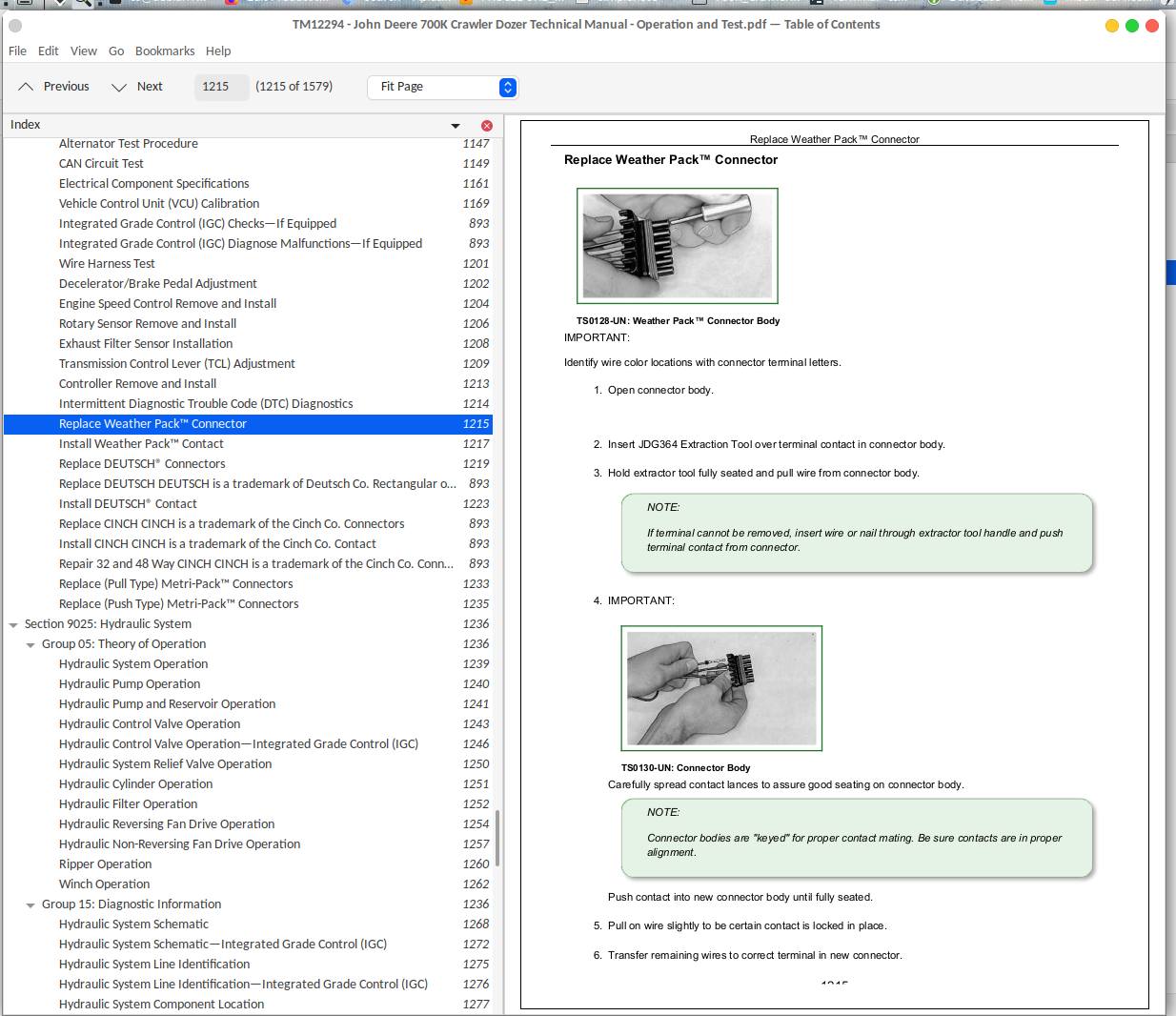
Replace Weather Pack™ Connector..........1215
Install Weather Pack™ Contact..........1217
Replace DEUTSCH® Connectors..........1219
Replace DEUTSCH DEUTSCH is a trademark of Deutsch Co. Rectangular or Triangular Connectors..........893
Install DEUTSCH® Contact..........1223
Replace CINCH CINCH is a trademark of the Cinch Co. Connectors..........893
Install CINCH CINCH is a trademark of the Cinch Co. Contact..........893
Repair 32 and 48 Way CINCH CINCH is a trademark of the Cinch Co. Connectors..........893
Replace (Pull Type) Metri-Pack™ Connectors..........1233
Replace (Push Type) Metri-Pack™ Connectors..........1235
Section 9025: Hydraulic System..........1236
Group 05: Theory of Operation..........1236
Hydraulic System Operation..........1239
Hydraulic Pump Operation..........1240
Hydraulic Pump and Reservoir Operation..........1241
Hydraulic Control Valve Operation..........1243
Hydraulic Control Valve Operation—Integrated Grade Control (IGC)..........1246
Hydraulic System Relief Valve Operation..........1250
Hydraulic Cylinder Operation..........1251
Hydraulic Filter Operation..........1252
Hydraulic Reversing Fan Drive Operation..........1254
Hydraulic Non-Reversing Fan Drive Operation..........1257
Ripper Operation..........1260
Winch Operation..........1262
Group 15: Diagnostic Information..........1236
Hydraulic System Schematic..........1268
Hydraulic System Schematic—Integrated Grade Control (IGC)..........1272
Hydraulic System Line Identification..........1275
Hydraulic System Line Identification—Integrated Grade Control (IGC)..........1276
Hydraulic System Component Location..........1277
Hydraulic System Component Location—Integrated Grade Control (IGC)..........1280
Hydraulic Reversing Fan Component Location..........1284
Hydraulic Non-Reversing Fan Component Location..........1286
Ripper Hydraulic Component Location..........1288
Winch Hydraulic Component Location..........1290
Hydraulic System Diagnose Malfunctions..........1236
Hydraulic System Diagnose Malfunctions—Integrated Grade Control (IGC)..........1236
Hydraulic Fan Does Not Reach Full Speed..........1236
Hydraulic Fan Runs at Full Speed Only..........1236
Hydraulic Fan Does Not Spin..........1236
Hydraulic Fan Will Not Reverse Direction..........1236
Group 20: Adjustments..........1236
Blade Pitch Linkage Adjustment..........1335
Blade Control Lever Linkage Adjustment..........1336
Auxiliary Hydraulic Control Lever Linkage Adjustment..........1338
Group 25: Tests..........1237
JT02156A Digital Pressure and Temperature Analyzer Kit Installation..........1341
Ultra Clean® Hand Launcher..........1342
Hydraulic Oil Warm-Up Procedure..........1343
Hydraulic Oil Sampling Procedure-If Equipped..........1344
Hydraulic Pump Flow Test..........1345
Hydraulic System Relief Valve Test..........1348
Hydraulic System Relief Valve Test—Integrated Grade Control (IGC)..........1350
Hydraulic Load Sense Circuit Bleed Procedure—Integrated Grade Control (IGC)..........1353
Circuit Relief Valve Test—With Remote Pump..........1355
Lift Cylinder Drift Test..........1358
Cylinder Leakage Test..........1360
Fan Pump Flow Test..........1362
Fan Motor Speed Test..........1365
Fan Motor Case Drain Test..........1368
Section 9026: Hydrostatic System..........1370
Group 05: Theory of Operation..........1370
Hydrostatic System Operation..........1373
Transmission Control Circuit Operation (Flow Chart)..........1374
Charge Pump Operation..........1376
Hydrostatic Charge Oil Filter Operation..........1377
Neutral Charge Relief Valve Operation..........1380
Park Brake Valve Operation..........1382
Multi-Function Valve Operation..........1383
Hydrostatic Thermal Bypass Valve Operation..........1385
Pump Pressure Control Pilot (PCP) Operation..........1387
Pump Displacement Control Valve (PDCV) Operation..........1389
Hydrostatic Pump Operation..........1391
Flushing Valve and Operating Charge Relief Valve Operation..........1393
Hydrostatic Motor Operation..........1395
Group 15: Diagnostic Information..........1370
Hydrostatic System Schematic..........1399
Hydrostatic System Line Identification..........1401
Hydrostatic System Component Location..........1403
Hydrostatic System Diagram—Neutral with Park Brake On..........1405
Hydrostatic System Diagram—Forward (Fast Speed)..........1407
Hydrostatic System Diagram—Reverse (Slow Speed)..........1409
Overheating Malfunctions..........1370
High/Low Charge Pressure Malfunctions..........1370
Mistrack/Index Malfunctions..........1370
Machine Full Speed Malfunctions..........1370
Low Power Malfunctions..........1370
Track Malfunctions..........1370
VCU Calibration Malfunctions..........1370
Group 25: Test..........1370
Transmission Oil Warm-Up Procedure..........1457
Hydrostatic Oil Sampling Procedure—If Equipped..........1460
Releasing Park Brake to Tow the Machine..........1461
Hydrostatic Pump Flushing Procedure..........1465
Pressure Control Pilot (PCP) Manual Override Test..........1467
Pressure Control Pilot (PCP) Test..........1469
Pressure Control Pilot (PCP) Internal Adjustment..........1473
Multi-Function Relief Valve Test..........1476
Transmission Efficiency Test..........1481
Neutral Charge Relief and Operating Charge Relief Pressure Test..........1486
Pump Displacement Control Valve (PDCV) Neutral (Null) Adjustment..........1489
Pump Servo Pressure Test..........1493
Motor Displacement Control Valve (MDCV) Adjustment..........1497
Hydrostatic Motor Min.-Max. Angle Servo Piston Pressure Test..........1501
Charge Pump Flow Test..........1504
Charge Pressure Sensor Test..........1507
Hydrostatic Thermal Bypass Valve Test..........1508
Section 9031: Heating and Air Conditioning..........1511
Group 05: Theory of Operation..........1511
Air Conditioning System Cycle Theory Of Operation..........1514
Group 15: Diagnostic Information..........1511
Air Conditioner and Heater Component Location..........1518
Diagnose Air Conditioning System Malfunctions..........1511
Air Conditioning System Does Not Operate..........1531
Air Conditioner Does Not Cool Interior of Cab..........1536
Air Conditioner Runs Constantly, Too Cold..........1540
Diagnose Heater System Malfunctions..........1511
Heater System Does Not Operate..........1547
Heater Does Not Warm Interior of Cab..........1551
Interior Windows Continue to Fog..........1554
Group 25: Test..........1511
Refrigerant Cautions and Proper Handling..........1556
R134a Refrigerant Cautions..........1557
R134a Oil Charge Capacity..........1558
R134a Refrigerant Charge Capacity..........1559
Air Conditioner and Heater Operational Checks..........1560
Refrigerant Leak Test..........1563
Air Conditioner Compressor Clutch Test..........1564
Air Conditioner High/Low Pressure Switch Test..........1565
Air Conditioner Freeze Control Switch Test..........1568
R134a Air Conditioning System Test..........1570
Operating Pressure Diagnostic Chart..........1573
John Deere 700K Operation & Test Technical Manual (TM12294)


