Caterpillar 308D CR Series Excavators Factory Service & Shop Manual
Catalog:
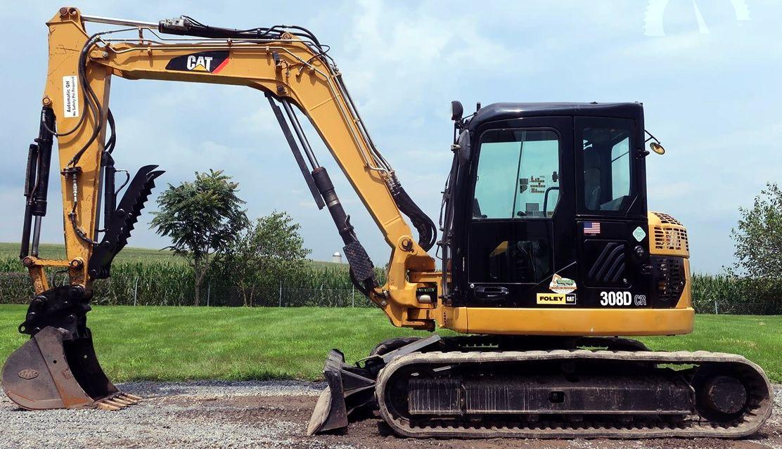
Model:
Complete workshop repair service manual with electrical wiring diagrams for Caterpillar 308D CR Series Excavators. It's the same service manual used by dealers that guaranteed to be fully functional and intact without any missing page.
Caterpillar 308D CR Series Excavators service & repair manual (including maintenance, overhaul, disassembling & assembling, adjustment, tune-up, operation, inspecting, diagnostic & troubleshooting…) is divided into different sections. Each section covers a specific component or system with detailed illustrations. A table of contents is placed at the beginning of each section. Pages are easily found by category, and each page is expandable for great detail. The printer-ready PDF documents work like a charm on all kinds of devices.
892 pages, bookmarked, Searchable, Printable, high quality PDF
MANUAL LIST:
KENR6164 - Systems Operation (308D CR Excavator Hydraulic System).pdf
KENR6165 - Testing and Adjusting (308D CR Mini Hydraulic Excavator Hydraulic System).pdf
KENR6799 - Specifications (308D, 314D, 321D and 328D Excavators Air Conditioning and Heating).pdf
KENR6799 - Systems Operation (308D, 314D, 321D and 328D Excavators Air Conditioning and Heating).pdf
KENR6799 - Testing and Adjusting (308D, 314D, 321D and 328D Excavators Air Conditioning and Heating).pdf
KENR7708 - Schematic (308D Excavator Hydraulic System).pdf
KENR8224 - Schematic (308D CR SB Excavator Electrical System).pdf
RENR9740 - Disassembly and Assembly (308D CR Excavator Engine Supplement).pdf
RENR9741 - Disassembly and Assembly (308D CR Excavator Machine Systems).pdf
...
KENR6163 - Specifications (308D Excavator Machine System)
Accumulator (Pilot)
Air Conditioner Lines
Auxiliary Hydraulic Lines - Long Stick
Auxiliary Hydraulic Lines - Medium Pressure Long Stick
Auxiliary Hydraulic Lines - Medium Pressure Medium Stick
Auxiliary Hydraulic Lines - Medium Stick
Blade Cylinder Lines
Blade Lift Cylinder
Blade Mounting
Boom - 3.39 m (11.1 ft)
Boom Cylinder Lines
Boom Cylinder
Boom Cylinder - Variable Angle
Boom Lines
Bucket Cylinder Lines
Bucket Cylinder
Bucket Linkage
Cab
Check Valve (Hydraulic Oil Cooler Bypass)
Control Manifold (Pilot Oil)
Counterweight
Cylinder (Thumb)
Engine Mounting
Fasteners
Final Drive
Front Idler
Front Lines
Fuel Lines
Fuel Tank
Handle Control (Travel)
Heater and Air Conditioner Mounting
Hydraulic Tank and Filter
Hydraulic Tank Mounting
Joystick Control
Main Hydraulic Pump Mounting
Main Hydraulic Pump
Operator Monitor
Pilot Lines
Pilot Valve (Joystick)
Pilot Valve (Travel)
Pump Coupling
Recoil Spring
Refrigerant Compressor Mounting
Sprocket
Stick Cylinder Lines
Stick Cylinder
Stick Lines - Long
Stick Lines - Medium
Stick - Long 2.21 m (7.3 ft)
Stick - Medium 1.67 m (5.5 ft)
Swing Boom Cylinder
Swing Drive
Swing Gear and Bearing
Swivel
Track Adjuster
Track Carrier Roller
Track
Track Roller (Center Flange)
Track Roller Mounting
Track Roller (Single Flange)
Travel Motor Guard
Travel Motor Lines
Upper Frame - Swing
Wiring (Battery)
KENR6164 - Systems Operation (308D CR Excavator Hydraulic System)
Accumulator (Pilot)
Blade Hydraulic System
Bucket Hydraulic System
Bypass Valve (Return) - Bypass Check Valve
Check Valve (Load)
Check Valve (Return Makeup) - Slow Return Check Valve
Control Valve (Boom Lowering)
Control Valve (Stick Lowering)
Cylinders (Boom, Stick and Bucket)
Displacement Change Valve
Final Drive
Gear Pump (Pilot)
General Information
Hydraulic Filter (Pilot)
Hydraulic Oil Cooler
Hydraulic Tank and Filter
Main Control Valve
Main Hydraulic Pump
Main Hydraulic System
Medium Pressure Hydraulic System
Oil Makeup (Swing System)
Oil Makeup (Travel System)
One-Way Flow Hydraulic System
Pilot Hydraulic System
Pilot Valve (Joystick)
Pilot Valve (Swing Parking Brake)
Pilot Valve (Travel)
Proportional Priority Pressure Compensation System - Metered Out
Pump Control (Main Hydraulic)
Relief Valve (Cushion Crossover) - Anti-Reaction Valve
Relief Valve (Line)
Relief Valve (Main)
Relief Valve (Pilot)
Relief Valve (Swing)
Return Hydraulic System
Solenoid Valve (Hydraulic Lockout)
Stick Hydraulic System
Swing Boom Hydraulic System
Swing Drive
Swing Hydraulic System
Swing Motor
Swivel
Travel Counterbalance Valve
Travel Hydraulic System
Travel Motor
Travel Parking Brake
Two-Way Flow Hydraulic System
KENR6165 - Testing and Adjusting (308D CR Mini Hydraulic Excavator Hydraulic System)
Accumulator (Pilot) - Test and Charge
Cylinder Drift - Check - Blade (If Equipped)
Cylinder Drift - Check - Empty Bucket
Cylinder Drift - Check - Loaded Bucket
Cylinder Speed - Check - Blade (If Equipped)
Cylinder Speed - Check - Boom Swing
Cylinder Speed - Check
Engine Performance - Test - Engine Speed
Event Codes
Gear Pump (Pilot) - Test
General Testing and Adjusting Information
Hydraulic System Air - Purge - Resonator Line
Hydraulic System Pressure - Release
Joystick Control - Calibrate - Slide Control
Machine Drift on a Slope - Check
Machine Tool Control System - Select
Main Hydraulic Pump Air - Purge
Main Pump (Flow) - Test
Operational Checks
Process for Setting Up the Work Tool
Pump Control (Output Flow) - Adjust
Relief Valve (Blade) - Test and Adjust - If Equipped
Relief Valve (Line) - Test and Adjust - Boom and Stick Lowering Control Valves (If Equipped)
Relief Valve (Line) - Test and Adjust
Relief Valve (Main) - Test and Adjust
Relief Valve (Pilot) - Test and Adjust
Relief Valve (Swing) - Test and Adjust
Solenoid Valve (Proportional Reducing) - Calibrate
Specifications
Swing Motor - Test - Measurement of Case Drain Oil
Swing Speed and Overswing on Level Ground - Check
Swing Speed and Swing Drift on a Slope - Check
Travel Motor - Test - Measurement of Case Drain Oil
Travel on Level Ground - Test - Optional Test
Travel on Level Ground - Test
Visual Inspection
Work Tool Parameter - Default Values
Work Tool Parameter - Program
Work Tool - Select
KENR6799 - Specifications (308D, 314D, 321D and 328D Excavators Air Conditioning and Heating)
Air Conditioner Lines
Blower Motor
Pressure Switch (Refrigerant Pressure Cutoff)
Refrigerant Compressor
System Capacities for Refrigerant (Excavators) - 308D CR-328D CR
KENR6799 - Systems Operation (308D, 314D, 321D and 328D Excavators Air Conditioning and Heating)
Actuator (Air Conditioner Control)
Air Conditioning and Heating System Sensor Operation
Air Conditioning System
Blower Motor
Control Module
Control Panel
Evaporator Coil
General Information
Heater Core (Cab)
Pressure Switch (Refrigerant Pressure Cutoff)
Refrigerant Compressor
Refrigerant Condenser
Refrigerant Expansion Valve
Refrigerant Receiver-Dryer
Speed Control - Power Transistor
KENR6799 - Testing and Adjusting (308D, 314D, 321D and 328D Excavators Air Conditioning and Heating)
Actuator Troubleshooting - Abnormal Detection
Actuator Troubleshooting - Guide for Actuators
Air Conditioning System Troubleshooting - Guide for Sensors
General Troubleshooting Information
Machine Preparation for Troubleshooting
Manifold Gauge Set (Refrigerant) - Install
Manifold Gauge Set (Refrigerant) - Remove
Refrigerant Compressor Oil - Check
Refrigerant Leakage - Test
Refrigerant Recovery
Refrigerant System - Charge
Refrigerant System - Evacuate
Refrigerant System - Flush
Required Tools
Sensor Troubleshooting
Visual Inspection
KENR7708 - Schematic (308D Excavator Hydraulic System)
Collage
Main
KENR8224 - Schematic (308D CR SB Excavator Electrical System)
Collage
Main
RENR9740 - Disassembly and Assembly (308D CR Excavator Engine Supplement)
Aftercooler - Remove and Install
Air Cleaner - Remove and Install
Alternator - Install
Alternator - Remove
Battery - Remove and Install
Electric Starting Motor - Remove and Install
Engine and Main Hydraulic Pump - Install
Engine and Main Hydraulic Pump - Remove
Engine Oil Filter and Oil Filter Base - Install
Engine Oil Filter and Oil Filter Base - Remove
Engine Oil Filter Base - Assemble
Engine Oil Filter Base - Disassemble
Fuel Filter and Water Separator Base - Remove and Install
Hood - Remove and Install
Hydraulic Oil Cooler - Remove and Install
Muffler - Remove and Install
Radiator and Hydraulic Oil Cooler - Install
Radiator and Hydraulic Oil Cooler - Remove
Radiator - Remove and Install
Refrigerant Compressor - Remove and Install
Refrigerant Condenser - Remove and Install
System Pressure - Release
Turbocharger - Install
Turbocharger - Remove
Water Temperature Regulator - Remove and Install
RENR9741 - Disassembly and Assembly (308D CR Excavator Machine Systems)
Accumulator - Remove and Install
Blade Cylinder - Remove and Install
Blade - Remove and Install
Blower Motor (Air Conditioner, Heater) - Remove and Install
Boom Cylinder - Remove and Install
Bucket Cylinder - Remove and Install
Bucket - Install
Bucket Linkage - Install
Bucket Linkage - Remove
Bucket - Remove
Cab - Install
Cab - Remove
Check Valve (Cooler Bypass) - Install
Check Valve (Cooler Bypass) - Remove
Check Valve (Slow Return) - Install
Check Valve (Slow Return) - Remove
Control Manifold (Pilot Oil) - Install
Control Manifold (Pilot Oil) - Remove
Counterweight - Remove and Install
Duo-Cone Conventional Seals - Install
Evaporator Coil - Install
Evaporator Coil - Remove
Final Drive and Travel Motor - Assemble
Final Drive and Travel Motor - Disassemble
Final Drive and Travel Motor - Install
Final Drive and Travel Motor - Remove
Front Idler and Recoil Spring - Install
Front Idler and Recoil Spring - Remove
Fuel Tank - Install
Fuel Tank - Remove
Gear Pump (Pilot) - Install
Gear Pump (Pilot) - Remove
Heater Core - Install
Heater Core - Remove
Heating and Air Conditioning Unit - Install
Heating and Air Conditioning Unit - Remove
Hydraulic Lockout Control - Install
Hydraulic Lockout Control - Remove
Hydraulic Tank - Install
Hydraulic Tank - Remove
Hydraulic Track Adjusters - Install
Hydraulic Track Adjusters - Remove
Main Control Valve - Assemble
Main Control Valve - Disassemble
Main Control Valve - Install
Main Control Valve - Remove
Main Hydraulic Pump - Assemble
Main Hydraulic Pump - Disassemble
Main Hydraulic Pump - Install
Main Hydraulic Pump - Remove
Oil Filter and Base - Remove and Install
Pilot Valve (Alternate Pattern Control) - Remove and Install
Pilot Valve (Blade) - Assemble
Pilot Valve (Blade) - Disassemble
Pilot Valve (Blade) - Install
Pilot Valve (Blade) - Remove
Pilot Valve (Joystick) - Assemble
Pilot Valve (Joystick) - Disassemble
Pilot Valve (Joystick) - Install
Pilot Valve (Joystick) - Remove
Pilot Valve (Travel) - Assemble
Pilot Valve (Travel) - Disassemble
Pilot Valve (Travel) - Install
Pilot Valve (Travel) - Remove
Receiver Dryer (Refrigerant) - Remove and Install
Recoil Spring - Assemble
Recoil Spring - Disassemble
Relief Valve (Pilot) - Remove and Install
Seat - Remove and Install
Seat Support - Remove and Install
Seat Suspension - Remove and Install
Solenoid Valve (Hydraulic Lockout) - Remove and Install
Solenoid Valve (Swing Boom) - Assemble
Solenoid Valve (Swing Boom) - Disassemble
Solenoid Valve (Swing Boom) - Install
Solenoid Valve (Swing Boom) - Remove
Solenoid Valve (Travel Speed) - Remove and Install
Solenoid Valve (Two-Way Flow and One Pump_Two Pump) - Assemble
Solenoid Valve (Two-Way Flow and One Pump_Two Pump) - Disassemble
Solenoid Valve (Two-Way Flow and One Pump_Two Pump) - Install
Solenoid Valve (Two-Way Flow and One Pump_Two Pump) - Remove
Sprocket - Remove and Install
Stick Cylinder - Remove and Install
Stick - Install
Stick - Remove
Support (Swing Boom) - Install
Support (Swing Boom) - Remove
Swing Boom Cylinder - Remove and Install
Swing Boom - Install
Swing Boom - Remove
Swing Drive - Assemble
Swing Drive - Disassemble
Swing Drive - Install
Swing Drive - Remove
Swing Gear and Bearing - Remove and Install
Swing Motor - Assemble
Swing Motor - Disassemble
Swing Motor - Install
Swing Motor - Remove
Swivel - Assemble
Swivel - Disassemble
Swivel - Install
Swivel - Remove
System Pressure - Release
Track Adjuster - Assemble
Track Adjuster - Disassemble
Track Carrier Roller - Remove and Install
Track - Remove and Install
Track Roller - Remove and Install
Undercarriage Frame - Install
Undercarriage Frame - Remove
Window Wiper Motor - Remove and Install
EXCERPT:
Blade RAISE
During a BLADE RAISE operation, the oil delivery from main pump (20) flows through line (19) to parallel feeder passage (5) in main control valve (2). Oil flows to blade control valve (12) .
Pilot pump (21) supplies oil to pilot control valve (16) through line (15). When the joystick for the blade is moved to the full BLADE RAISE position, the pilot oil flows from pilot control valve (16) through pilot line (13). The pilot oil flows to blade control valve (12) .
The pilot oil flow shifts blade control valve (12) for BLADE RAISE operation. The oil delivery from the main pump in parallel feeder passage (5) flows through passage (8) through blade control valve (12). The oil delivery from the main pump then flows through line (6) to the head end of blade cylinder (1) .
Return oil from the rod end of blade cylinder (1) flows through line (11) to blade control valve (12). The oil then flows through passage (9) and through return line (17) and line (18) to the hydraulic tank (23) .
Blade FLOAT
In the FLOAT position, no pump oil is supplied to the blade cylinder. No hydraulic control is used on the blade cylinder. The mass (size and weight) of the blade causes the blade to stay on the ground. The FLOAT position is suitable for levelling work on a soft surface.
When the blade control lever is moved forward into the detent position, the blade is placed in the FLOAT position. Blade control valve (12) shifts for the FLOAT operation. This allows oil to flow from the rod end of the cylinder and the head end of the cylinder through blade control valve (12).
...


