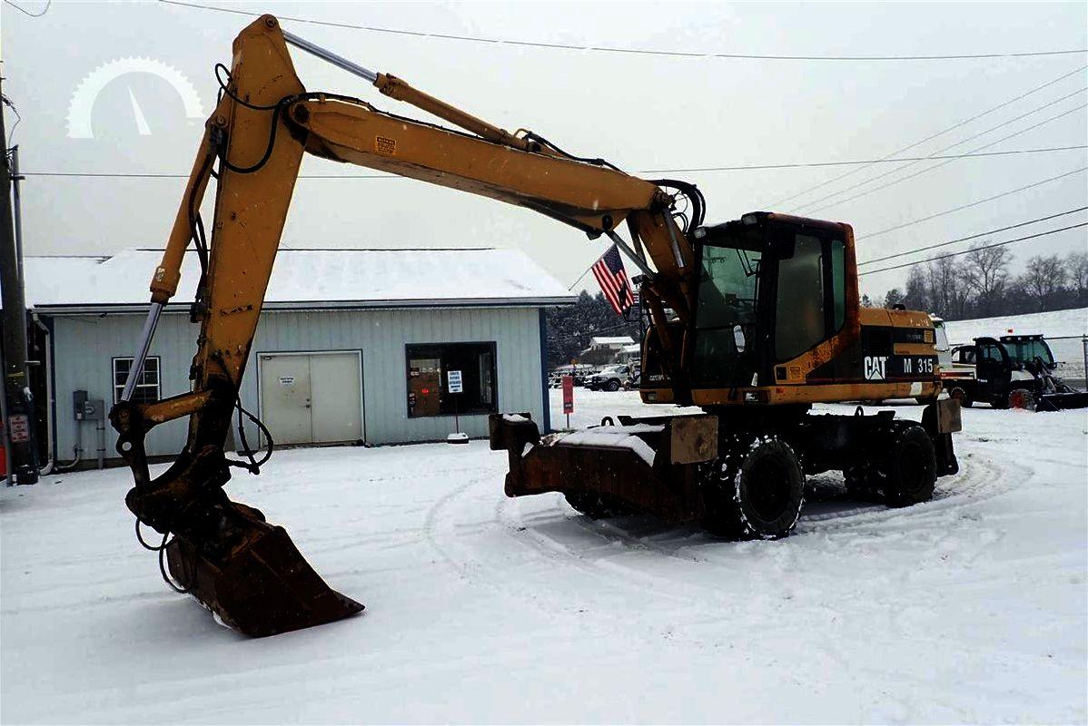
Caterpillar M315 Excavators Factory Service & Shop Manual
Catalog:
Model:
Complete workshop repair service manual with electrical wiring diagrams for Caterpillar M315 Excavators. It's the same service manual used by dealers that guaranteed to be fully functional and intact without any missing page.
This Caterpillar M315 Excavators service & repair manual (including maintenance, overhaul, disassembling & assembling, adjustment, tune-up, operation, inspecting, diagnostic & troubleshooting…) is divided into different sections. Each section covers a specific component or system with detailed illustrations. A table of contents is placed at the beginning of each section. Pages are easily found by category, and each page is expandable for great detail. The printer-ready PDF documents work like a charm on all kinds of devices.
2,176 pages, bookmarked, Searchable, Printable, high quality PDF
MANUAL LIST:
RENR1158 - Specifications (M312, M315, M318 and M320 Excavators Air Conditioning and Heating)
RENR1158 - Systems Operation (M312, M315, M318 and M320 Excavators Air Conditioning and Heating)
RENR1158 - Testing and Adjusting (M312, M315, M318 and M320 Excavators Air Conditioning and Heating)
RENR1168 - Schematic (M312, M315 and M318 Excavators Hydraulic System (Attachment) Auxitiary Circuit)
RENR1169 - Schematic (M312, M315 & M318 Excavators Hydraulic System - Attachment - Zeppelin Metal Work 123-3229)
RENR1175 - Disassembly and Assembly (M312 and M315 Excavators Machine Systems)
RENR1181 - Testing and Adjusting (M315 Excavator Hydraulic System)
RENR1185 - Schematic (M312, M315 and M318 Wheeled Excavators Hydraulic System)
RENR1186 - Schematic (M312, M315 and M318 Excavators Hydraulic System - Attachment Auxiliary Circuit)
RENR1187 - Schematic (M312, M315 and M318 Excavators Equipped with ZMW Hydraulics (Attachment))
RENR1196 - Schematic (M312 and M315 Excavator Electrical System)
RENR1197 - Schematic (M312 & M315 EXCAVATORS HYDRAULIC SYSTEM)
RENR1198 - Schematic (M312 and M315 Excavators Hydraulic System (Attachment) Auxilliary Circuit)
RENR1199 - Systems Operation (M312 and M315 Excavators Machine Electronic Control System)
RENR1199 - Testing and Adjusting (M312 and M315 Excavators Machine Electronic Control System)
RENR4023 - Disassembly and Assembly (M312 and M315 Excavators Machine Systems Supplement)
RENR4026 - Disassembly and Assembly (M312 and M315 Excavators Power Train Supplement)
RENR4033 - Schematic (M312 and M313 Wheeled Excavator Electrical System)
SENR6260 - Systems Operation (M312, M315, M318 and M320 Excavators Hydraulic System)
SENR8923 - Disassembly and Assembly (SUPPLEMENT FOR M315 EXCAVATORS - 3054 ENGINE)
SENR8924 - Disassembly and Assembly (M315 EXCAVATOR POWER TRAIN)
SENR8925 - Specifications (M315 Excavator Machine System)
SENR8926 - Systems Operation (M315 EXCAVATOR HYDRAULIC SYSTEMS).pdf
SENR8928 - Systems Operation (M315 EXCAVATOR STABILIZER_DOZER, TRAVEL, DRIVE & STEERING SY,).pdf
SENR8929 - Schematic (M312 and M315 Excavators Hydraulic System)
SENR8930 - Disassembly and Assembly (M315 EXCAVATOR MACHINE SYSTEMS)
SENR8931 - Systems Operation (ELECTRONIC CONTROL SYSTEM FOR M312 AND M315 EX.).pdf
SENR8931 - Testing And Adjusting (ELECTRONIC CONTROL SYSTEM FOR M312 AND M315 EX.).pdf
SENR8932 - Schematic (M312 and M315 Excavator Electrical System)
SENR8956 - Systems Operation (M300 SERIES EXCAVATORS ATTACHMENTS).pdf
SENR8956 - Testing And Adjusting (M300 SERIES EXCAVATORS ATTACHMENTS).pdf
EXCERPT:
8. Remove two bolts (10), the washers and nuts that hold exhaust tube assembly (9) to the mounting bracket.
Remove exhaust pipe assembly (11) and exhaust tube assembly (9), as a unit, from the machine.
9. Remove the four socket head bolts that hold the exhaust tube assembly to the exhaust pipe assembly.
Separate the exhaust tube assembly from the exhaust pipe assembly.
NOTE: The following steps are for the installation of the muffler group.
10. Connect exhaust tube assembly (9) to exhaust pipe assembly (11) using the four socket head bolts.
11. Put the exhaust tube assembly and the exhaust pipe assembly, as a unit, in position in the machine.
12. Connect exhaust pipe assembly (11) to the turbocharger using three nuts (8).
13. Install two bolts (10), the washer sand nuts that hold exhaust tube assembly to the mounting bracket.
14. Install heat shield plate assembly (7) over the turbocharger and the exhaust pipe assembly.
15. Put muffler (6) in position in the two muffler clamp assemblies. Connect the muffler to tube assembly (2).
Install two bolts (5), the four washers and two nuts that hold the muffler in the muffler clamp assemblies.
Install clamp (3).
16. Put exhaust pipe (1) in position on the muffler. Install clamp (4) that holds the exhaust pipe in position.
...


