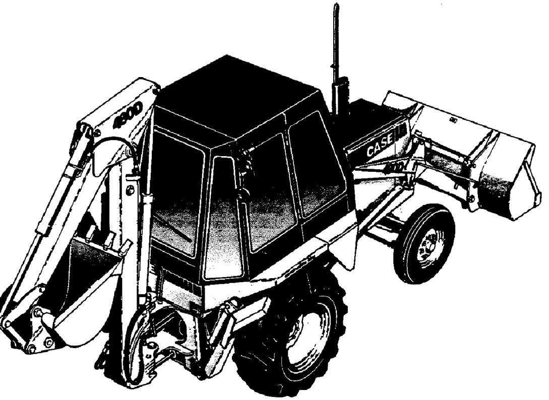
Case 480D & 480LL Factory Service & Shop Manual
Catalog:
Model:
Complete workshop repair & service manual with electrical wiring diagrams for Case 480D & 480LL . It's the same service manual used by dealers that guaranteed to be functional and intact without any missing page.
Case Construction 480D & 480LL service repair manual (including maintenance, overhaul, disassembling & assembling, adjustment, tune-up, operation, inspecting, diagnostic & troubleshooting…) is divided into different sections. Each section covers a specific component or system with detailed iLLustrations. A table of contents is placed at the beginning of each section. Pages are easily found by category, and each page is expandable for great detail. The printer-ready PDF documents work like a charm on aLL kinds of devices.
Case 480D & 480LL Service Manual.pdf; 1,200 pages
EXCERPT:
FRONT AXLE
Removal
1. Raise the front wheels high enough so that the front axle can be lowered out of the frame.
2. Put an acceptable support under each side of the frame.
3. Raise the loader frame aLL the way and engage the strut on the' loader frame with the lift cylinder.
4. Disconnect the hoses from the steering control valve at the tee fittings in the left steering cylinder.
5. InstaLL a cap on the tee fittings and a plug in the hoses.
6. Remove the snap ring and flat washer from the rear of the pivot pin for the front axle.
7. Lift one side of the front axle to remove the weight from the pivot pin.
8. Use an acceptable driver and a hammer and drive the pivot pin out of the front axle.
9. Lower the front axle while keeping the front axle in balance from front to rear.
Bushing InstaLLation
There are three bushings used in the front axle; one in the yoke and two in the beam. There is also a bushing instaLLed in the front and rear mounting plate for the front axle. See Figure 2.
1. The bushing in the yoke must be centered in the yoke. Use an acceptable driver and a hammer or portable press to drive the bushing into place.
2. The bushings in the beam must be even with the front and rear of the beam so that the bushings and pivot pin can be lubricated.
3. InstaLL the bushing in the front and rear mounting plate so that the bushing does not extend past the front axle side of the mounting plate.
InstaLLation
1. Raise the front axle into the frame.
…


