John Deere 310SL Backhoe Loader Workshop Service Repair Manual (TM13298X19)
Catalog:
Model:
John Deere 310SL Backhoe Loader Workshop Service Repair (including maintenance, overhaul, disassembling & assembling, adjustment, tune-up, operation, inspecting …) is divided into different sections. Each section covers a specific component or system with detailed illustrations. A table of contents is placed at the beginning of each section. Pages are easily found by category, and each page is expandable for great detail. The printer-ready PDF documents work like a charm on all kinds of devices.
This manual contains high quality images, instructions to help you to maintenance, troubleshoot, diagnose, and repair. This document is printable, without restrictions, contains searchable text, bookmarks, crosslinks for easy navigation.
TM13298X19 - John Deere 310SL Backhoe Loader Technical Manual (Repair).pdf
TABLE OF CONTENTS / FILE LIST:
Foreword
Manual Identification—READ THIS FIRST!
Section 00: General Information
Group 0001: Safety
Recognize Safety Information
Follow Safety Instructions
Operate Only If Qualified
Wear Protective Equipment
Avoid Unauthorized Machine Modifications
Inspect Machine
Stay Clear of Moving Parts
Avoid High-Pressure Fluids
Avoid High-Pressure Oils
Work In Ventilated Area
Avoid Static Electricity Risk When Refueling
Prevent Fires
In Case of Machine Fire
Prevent Battery Explosions
Handle Chemical Products Safely
Exhaust Filter Ash Handling and Disposal
Prepare for Emergencies
Clean Debris from Machine
Decommissioning — Proper Recycling and Disposal of Fluids and Components
Use Steps and Handholds Correctly
Start Only From Operator's Seat
Use and Maintain Seat Belt
Prevent Unintended Machine Movement
Prevent Unintended Machine Movement—If Equipped With Pilot Controls
Avoid Work Site Hazards
Keep Riders Off Machine
Avoid Backover Accidents
Avoid Machine Tipover
Operating or Traveling On Public Roads
Inspect and Maintain ROPS
Travel Safely
Prevent Acid Burns
Add and Operate Attachments Safely
Use Special Care When Operating
Park and Prepare for Service Safely
Service Cooling System Safely
Remove Paint Before Welding or Heating
Make Welding Repairs Safely
Drive Metal Pins Safely
Follow Tire Recommendations
Service Tires Safely
Clean Exhaust Filter Safely
Group 0003: Torque Values
Metric Bolt and Cap Screw Torque Values
Additional Metric Cap Screw Torque Values
Unified Inch Bolt and Cap Screw Torque Values
Service Recommendations for 37° Flare and 30° Cone Seat Connectors
Service Recommendations for O-Ring Boss Fittings
O-Ring Boss Fittings in Aluminum Housing Service Recommendations—Excavators
Service Recommendations for Flared Connections—Straight or Tapered Threads
Service Recommendations for Flat Face O-Ring Seal Fittings
O-Ring Face Seal Fittings With SAE Inch Hex Nut and Stud End for High-Pressure Service Recommendations
O-Ring Face Seal Fittings With Metric Hex Nut and Stud End for Standard Pressure Service Recommendations
O-Ring Face Seal Fittings With Metric Hex Nut and Stud End for High-Pressure Service Recommendations
Service Recommendations for Metric Series Four Bolt Flange Fitting
Service Recommendations For Inch Series Four Bolt Flange Fittings
Inch Series Four Bolt Flange Fitting for High-Pressure Service Recommendations
Service Recommendations For Non-Restricted Banjo (Adjustable) Fittings
Service Recommendations For O-Ring Boss Fittings With Shoulder
Metric 24° O-Ring Seal DIN 20078 Service Recommendations
Recognize Safety Information
Recognize Safety Information
Follow Safety Instructions
Operate Only If Qualified
Wear Protective Equipment
Avoid Unauthorized Machine Modifications
Inspect Machine
Stay Clear of Moving Parts
Avoid High-Pressure Fluids
Avoid High-Pressure Oils
Work In Ventilated Area
Avoid Static Electricity Risk When Refueling
Prevent Fires
In Case of Machine Fire
Prevent Battery Explosions
Handle Chemical Products Safely
Exhaust Filter Ash Handling and Disposal
Prepare for Emergencies
Clean Debris from Machine
Decommissioning — Proper Recycling and Disposal of Fluids and Components
Use Steps and Handholds Correctly
Start Only From Operator's Seat
Use and Maintain Seat Belt
Prevent Unintended Machine Movement
Prevent Unintended Machine Movement—If Equipped With Pilot Controls
Avoid Work Site Hazards
Keep Riders Off Machine
Avoid Backover Accidents
Avoid Machine Tipover
Operating or Traveling On Public Roads
Inspect and Maintain ROPS
Travel Safely
Prevent Acid Burns
Add and Operate Attachments Safely
Use Special Care When Operating
Park and Prepare for Service Safely
Service Cooling System Safely
Remove Paint Before Welding or Heating
Make Welding Repairs Safely
Drive Metal Pins Safely
Follow Tire Recommendations
Service Tires Safely
Clean Exhaust Filter Safely
Metric Bolt and Cap Screw Torque Values
Metric Bolt and Cap Screw Torque Values
Additional Metric Cap Screw Torque Values
Unified Inch Bolt and Cap Screw Torque Values
Service Recommendations for 37° Flare and 30° Cone Seat Connectors
Service Recommendations for O-Ring Boss Fittings
Straight Fitting
Angle Fitting
O-Ring Boss Fittings in Aluminum Housing Service Recommendations—Excavators
Service Recommendations for Flared Connections—Straight or Tapered Threads
Service Recommendations for Flat Face O-Ring Seal Fittings
O-Ring Face Seal Fittings With SAE Inch Hex Nut and Stud End for High-Pressure Service Recommendations
O-Ring Face Seal Fittings With Metric Hex Nut and Stud End for Standard Pressure Service Recommendations
O-Ring Face Seal Fittings With Metric Hex Nut and Stud End for High-Pressure Service Recommendations
Service Recommendations for Metric Series Four Bolt Flange Fitting
Service Recommendations For Inch Series Four Bolt Flange Fittings
Inch Series Four Bolt Flange Fitting for High-Pressure Service Recommendations
Service Recommendations For Non-Restricted Banjo (Adjustable) Fittings
Service Recommendations For O-Ring Boss Fittings With Shoulder
Metric 24° O-Ring Seal DIN 20078 Service Recommendations
Section 01: Wheels
Group 0110: Powered or Non-Powered Wheels and Fastenings
Rear Wheel Assembly Remove and Install
Front Wheel Assembly Remove and Install
Tire Remove and Install
Rear Wheel Assembly Remove and Install
Rear Wheel Assembly Remove and Install
Front Wheel Assembly Remove and Install
Tire Remove and Install
Section 02: Axles and Suspension Systems
Group 0225: Input Drive Shafts and U-Joints
Universal Joint and Drive Shaft Remove and Install
Group 0230: Non-Powered Wheel Axles
Hub Assembly Remove and Install
Spindle Assembly Remove and Install
Tie Rod Remove and Install
Non-Powered Front Axle Remove and Install—If Equipped
Group 0240: Powered Wheel Axle (MFWD)
Mechanical Front Wheel Drive (MFWD) Axle Remove and Install
Mechanical Front Wheel Drive (MFWD) Axle Disassembly
Mechanical Front Wheel Drive (MFWD) Axle Assemble
Limited Slip Differential Disassemble and Assemble
Group 0250: Axle Shaft, Bearings, and Reduction Gears
Service Brakes Inspection
Rear Axle Remove and Install
Rear Axle Disassemble
Rear Axle Assemble
Park Brake Disassemble and Assemble
Gear Tooth Contact Pattern Check
Universal Joint and Drive Shaft Remove and Install
Rear Drive Shaft Remove and Install
MFWD Drive Shaft Remove and Install—If Equipped
U-Joint Remove and Install
Universal Joint and Drive Shaft Remove and Install
Rear Drive Shaft Remove and Install
MFWD Drive Shaft Remove and Install—If Equipped
U-Joint Remove and Install
Hub Assembly Remove and Install
Hub Assembly Remove and Install
Spindle Assembly Remove and Install
Tie Rod Remove and Install
Nonpowered Axle
Mechanical Front Wheel Drive (MFWD) Axle
Non-Powered Front Axle Remove and Install—If Equipped
Mechanical Front Wheel Drive (MFWD) Axle Remove and Install
Mechanical Front Wheel Drive (MFWD) Axle Remove and Install
Mechanical Front Wheel Drive (MFWD) Axle Disassembly
Planetary Drive Removal
Ring Gear Removal
Planetary Gears Removal
Wheel Hub Removal and Disassembly
Tie Rods Removal
Steering Cylinder Removal
Knuckle Housing Removal
Drive Shaft Remove
Knuckle Housing Disassembly
Drive Shaft Disassembly
Axle Housing Disassemble
Mechanical Front Wheel Drive (MFWD) Axle Assemble
Axle Housing Assemble
Knuckle Housing Assemble
Drive Shaft Assemble
Drive Shaft Install
Knuckle Housing Install
Wheel Hub Assemble
Wheel Hub Install
Ring Gear Install
Planetary Gears Install
Planetary Carrier Install
Steering Cylinder Install
Tie Rods Install
Limited Slip Differential Disassemble and Assemble
Service Brakes Inspection
Service Brakes Inspection
Rear Axle Remove and Install
Rear Axle Disassemble
Rear Axle Assemble
Park Brake Disassemble and Assemble
Gear Tooth Contact Pattern Check
Section 03: Transmission
Group 0300: Removal and Installation
Transmission Remove and Install
Group 0350: Gear, Shafts, and Power Shift Clutches
Transmission Outer Components Removal
Transmission Outer Components Install
Transmission Case Disassemble—Torque Converter Side
Transmission Case Assemble—Torque Converter Side
Clutch Packs Remove
Clutch Packs Install
High Range Forward, Low Range Forward, and Reverse Clutch Packs Disassemble and Assemble
First Speed and Third Speed Clutch Disassemble and Assemble
Second Speed Clutch Disassemble and Assemble
Mechanical Front Wheel Drive (MFWD) Clutch Disassemble and Assemble
Pump Drive Shaft Install
Group 0360: Hydraulic System
Transmission Charge Pump Remove and Install
Transmission Charge Pump Disassemble and Assemble
Transmission Remove and Install
Transmission Remove and Install
Transmission Outer Components Removal
Transmission Outer Components Removal
Transmission Outer Components Install
Transmission Case Disassemble—Torque Converter Side
Transmission Case Assemble—Torque Converter Side
Clutch Packs Remove
Clutch Packs Install
High Range Forward, Low Range Forward, and Reverse Clutch Packs Disassemble and Assemble
First Speed and Third Speed Clutch Disassemble and Assemble
Second Speed Clutch Disassemble and Assemble
DISASSEMBLE
ASSEMBLE
Mechanical Front Wheel Drive (MFWD) Clutch Disassemble and Assemble
Pump Drive Shaft Install
Transmission Charge Pump Remove and Install
Transmission Charge Pump Remove and Install
Transmission Charge Pump Disassemble and Assemble
Section 04: Engine
Group 0400: Removal and Installation
John Deere Engine Operation
Engine Remove and Install
John Deere Engine Operation
John Deere Engine Operation
Engine Remove and Install
REMOVAL
INSTALLATION
Section 05: Engine Auxiliary System
Group 0505: Cold Weather Starting Aids
Coolant Heater Remove and Install—If Equipped
Group 0510: Cooling Systems
Fan Remove and Install
Fan Disassemble and Assemble
Accessory Drive Belt Remove and Install
Cooling Package Disassemble and Assemble
Cooling Package Remove and Install
Group 0520: Intake System
Air Cleaner Remove and Install
Charge Air Cooler Remove and Install
Group 0530: Exhaust Systems
Service Filter Cleaning
JDG11340 Bellows Alignment Fixture
Exhaust Bellows Alignment Procedure
Aftertreatment Assembly Remove and Install
Exhaust Filter Remove and Install
Exhaust Tube Remove and Install
Diesel Exhaust Fluid (DEF) Tank Remove and Install
Diesel Exhaust Fluid (DEF) Header Remove and Install
Diesel Exhaust Fluid (DEF) Header Disassemble and Assemble
Diesel Exhaust Fluid (DEF) Tank Cleaning Procedure
Diesel Exhaust Fluid (DEF) Dosing Unit Remove and Install
Diesel Exhaust Fluid (DEF) Dosing Injector Remove and Install
Diesel Exhaust Fluid (DEF) Decomposition Tube Remove and Install
Group 0560: External Fuel Supply Systems
Fuel Tank Remove and Install
Coolant Heater Remove and Install—If Equipped
Coolant Heater Remove and Install—If Equipped
Fan Remove and Install
REMOVAL
INSTALLATION
Fan Remove and Install
REMOVAL
INSTALLATION
Fan Disassemble and Assemble
DISASSEMBLE
ASSEMBLE
Accessory Drive Belt Remove and Install
Cooling Package Disassemble and Assemble
DISASSEMBLE
ASSEMBLE
DISASSEMBLE
ASSEMBLE
Cooling Package Remove and Install
REMOVAL
INSTALLATION
Air Cleaner Remove and Install
Machine Preparation
Additional Information
Air Cleaner Remove and Install
Machine Preparation
Additional Information
Charge Air Cooler Remove and Install
MACHINE PREPARATION
REMOVAL
INSTALLATION
Service Filter Cleaning
Service Filter Cleaning
JDG11340 Bellows Alignment Fixture
Exhaust Bellows Alignment Procedure
Tools
Machine Preparation
Exhaust Bellows Alignment Procedure
Aftertreatment Assembly Remove and Install
REMOVAL
INSTALLATION
Exhaust Filter Remove and Install
REMOVAL
INSTALLATION
Exhaust Tube Remove and Install
REMOVAL
INSTALLATION
Diesel Exhaust Fluid (DEF) Tank Remove and Install
Diesel Exhaust Fluid (DEF) Header Remove and Install
MACHINE PREPARATION
REMOVAL AND INSTALLATION (S.N. —303523)
REMOVAL AND INSTALLATION (S.N. 303524— )
Diesel Exhaust Fluid (DEF) Header Disassemble and Assemble
Diesel Exhaust Fluid (DEF) Baffle Remove and Install
Diesel Exhaust Fluid (DEF) Tank Header Suction Screen Remove and Install (S.N. —303523)
Diesel Exhaust Fluid (DEF) Tank Header Suction Filter Remove and Install (S.N. 303524— )
Diesel Exhaust Fluid (DEF) Tank Cleaning Procedure
Cleaning Procedure—DEF Tank Removed
Cleaning Procedure—DEF Tank Installed
Diesel Exhaust Fluid (DEF) Dosing Unit Remove and Install
REMOVAL
INSTALLATION
Diesel Exhaust Fluid (DEF) Dosing Injector Remove and Install
Diesel Exhaust Fluid (DEF) Decomposition Tube Remove and Install
Fuel Tank Remove and Install
REMOVAL
INSTALLATION
Fuel Tank Remove and Install
REMOVAL
INSTALLATION
Section 06: Torque Converter
Group 0651: Turbine, Gears, and Shaft
Torque Converter Remove and Install
Torque Converter Remove and Install
Torque Converter Remove and Install
Section 09: Steering System
Group 0920: Power Steering
Steering Column Remove and Install
Steering Wheel and Column Disassemble and Assemble
Group 0960: Power Steering Hydraulic System
Steering Valve Remove and Install
Steering Valve Disassemble and Assemble
Non-Powered Axle Steering Cylinder Remove and Install
Non-Powered Axle Steering Cylinder Disassemble and Assemble
Mechanical Front Wheel Drive (MFWD) Axle Steering Cylinder Remove and Install
Mechanical Front Wheel Drive (MFWD) Axle Steering Cylinder Disassemble and Assemble
Steering Column Remove and Install
Tilt Steering Column
INSTALLATION
Standard Steering Column
INSTALLATION
Steering Column Remove and Install
Tilt Steering Column
INSTALLATION
Standard Steering Column
INSTALLATION
Steering Wheel and Column Disassemble and Assemble
Steering Valve Remove and Install
REMOVAL
INSTALLATION
Steering Valve Remove and Install
REMOVAL
INSTALLATION
Steering Valve Disassemble and Assemble
Non-Powered Axle Steering Cylinder Remove and Install
Non-Powered Axle Steering Cylinder Disassemble and Assemble
Mechanical Front Wheel Drive (MFWD) Axle Steering Cylinder Remove and Install
Mechanical Front Wheel Drive (MFWD) Axle Steering Cylinder Disassemble and Assemble
Section 10: Service Brakes
Group 1011: Active Elements
Brake Disc and Pressure Plate Remove and Install
Group 1015: Controls Linkage
Brake Pedal Adjustment
Group 1060: Hydraulic System
Brake System Bleeding Procedure
Power Boost Brake Valve Remove and Install
Brake Valve Disassemble and Assemble
Brake Disc and Pressure Plate Remove and Install
Brake Disc and Pressure Plate Remove and Install
Brake Pedal Adjustment
Brake Pedal Adjustment
Brake System Bleeding Procedure
Brake System Bleeding Procedure
Power Boost Brake Valve Remove and Install
REMOVAL
INSTALLATION
Brake Valve Disassemble and Assemble
Section 11: Park Brake
Group 1111: Active Elements
Park Brake Remove and Install
Park Brake Remove and Install
Park Brake Remove and Install
Section 16: Electrical System
Group 1600: Remove and Install
Installation of Repair Wire Assembly (RWA)
Electronic Controllers Remove and Install
Remove Connector Body from Blade Terminals
CINCH™ Connector Remove and Install
CINCH™ Contact Installation
CINCH™ CP Connector Remove and Install
CINCH™ CP Contact Installation
DEUTSCH® Connector Remove and Install
DEUTSCH® Contact Installation
Metri-Pack® Connector Remove and Install
WEATHER PACK® Connector Remove and Install
WEATHER PACK® Contact Installation
Seat Position Sensor Remove and Install
Group 1675: System Controls
Multi-Function Lever (MFL) Remove and Install
Transmission Control Lever (TCL) Remove and Install
Installation of Repair Wire Assembly (RWA)
Install Repair Wire Assembly (RWA)—Method 1
Install Repair Wire Assembly (RWA)—Method 2
Installation of Repair Wire Assembly (RWA)
Install Repair Wire Assembly (RWA)—Method 1
Install Repair Wire Assembly (RWA)—Method 2
Electronic Controllers Remove and Install
Remove Connector Body from Blade Terminals
CINCH™ Connector Remove and Install
CINCH™ Contact Installation
CINCH™ CP Connector Remove and Install
Connector Removal
Connector Installation
CINCH™ CP Contact Installation
DEUTSCH® Connector Remove and Install
Circular Connectors
Rectangular or Triangular Connectors
DEUTSCH® Contact Installation
Metri-Pack® Connector Remove and Install
Pull-Type Connector
Push-Type Connector
WEATHER PACK® Connector Remove and Install
WEATHER PACK® Contact Installation
Seat Position Sensor Remove and Install
REMOVAL
INSTALLATION
Multi-Function Lever (MFL) Remove and Install
Multi-Function Lever (MFL) Remove and Install
Transmission Control Lever (TCL) Remove and Install
Section 17: Frame or Supporting Structure
Group 1740: Frame Installation
Welding Repair of Major Structures
Rivet Nut Fasteners Remove and Install
Group 1749: Chassis Weights
Counterweight Remove and Install—If Equipped
Welding Repair of Major Structures
Welding Repair of Major Structures
Rivet Nut Fasteners Remove and Install
Counterweight Remove and Install—If Equipped
Counterweight Remove and Install—If Equipped
Section 18: Operator's Station
Group 1800: Removal and Installation
Operator’s Station Remove and Install
Group 1810: Operator Enclosure
Front Window Wiper and Wiper Motor Remove and Install
Rear Window Wiper and Wiper Motor Remove and Install
Rear Window and Frame Assembly Remove and Install
Front Console Remove and Install
Fixed Window Remove and Install
Non-Fixed Window Remove and Install
Non-Fixed Window Adjustment
Non-Fixed Window Latch Adjustment
Cab Door Hinges and Latch Adjustment
Headliner Remove and Install
Cab Roof Remove and Install
Group 1821: Seat and Seat Belt
Seat Assembly Remove and Install
Mechanical Suspension Seat Disassemble and Assemble
Air Suspension Seat Disassemble and Assemble—If Equipped
Group 1830: Heating and Air Conditioning
R134a Refrigerant Cautions and Proper Handling
R134a Refrigerant Oil Information
R134a Refrigerant Recovery, Recycling, and Charging Station Installation Procedure
Recover R134a Refrigerant
Flush and Purge Air Conditioning System
Evacuate R134a System
Charge R134a System
Evaporator or Heater Core Remove and Install
Expansion Valve Remove and Install
Air Conditioner Freeze Control Switch Remove and Install
Receiver-Dryer Remove and Install
Blower Mode Door Motor Remove and Install
Condenser Remove and Install
Compressor Remove and Install
Operator’s Station Remove and Install
REMOVAL
INSTALLATION
Operator’s Station Remove and Install
REMOVAL
INSTALLATION
Front Window Wiper and Wiper Motor Remove and Install
REMOVAL
INSTALLATION
Front Window Wiper and Wiper Motor Remove and Install
REMOVAL
INSTALLATION
Rear Window Wiper and Wiper Motor Remove and Install
Rear Window and Frame Assembly Remove and Install
MACHINE PREPARATION
REMOVAL
INSTALLATION
Front Console Remove and Install
REMOVAL
INSTALLATION
Fixed Window Remove and Install
Non-Fixed Window Remove and Install
Upper and Middle Sliding Window (11 and 12)
Lower Fixed Window (13)
Cab Door Upper Window and Side Window
Non-Fixed Window Adjustment
Cab Door Upper Window
Side Windows
Non-Fixed Window Latch Adjustment
Cab Door Hinges and Latch Adjustment
Headliner Remove and Install
Cab Roof Remove and Install
Seat Assembly Remove and Install
Seat Assembly Remove and Install
Mechanical Suspension Seat Disassemble and Assemble
Air Suspension Seat Disassemble and Assemble—If Equipped
R134a Refrigerant Cautions and Proper Handling
R134a Refrigerant Cautions and Proper Handling
R134a Refrigerant Oil Information
R134a Refrigerant Recovery, Recycling, and Charging Station Installation Procedure
Recover R134a Refrigerant
Flush and Purge Air Conditioning System
Procedure Set-Up
Condenser Flush and Purge
Evaporator Flush and Purge
Procedure Wrap-Up
Evacuate R134a System
Charge R134a System
Evaporator or Heater Core Remove and Install
Expansion Valve Remove and Install
Air Conditioner Freeze Control Switch Remove and Install
Receiver-Dryer Remove and Install
Blower Mode Door Motor Remove and Install
Condenser Remove and Install
Compressor Remove and Install
MACHINE PREPARATION
REMOVAL
INSTALLATION
Section 19: Sheet Metal and Styling
Group 1910: Hood or Engine Enclosure
Hood and Engine Enclosure Remove and Install
Group 1913: Miscellaneous Shields
Battery Box Remove and Install
Hood and Engine Enclosure Remove and Install
Hood and Engine Enclosure Remove and Install
Battery Box Remove and Install
Dual Batteries
Single Battery
Battery Box Remove and Install
Dual Batteries
Single Battery
Section 20: Safety and Convenience
Group 2001: Radio
Radio and Speakers Remove and Install
Group 2004: Horn and Warning Devices
Backup Alarm Volume Adjustment
Radio and Speakers Remove and Install
Speakers
Standard Radio Package
Satellite Radio Package—If Equipped
Radio and Speakers Remove and Install
Speakers
Standard Radio Package
Satellite Radio Package—If Equipped
Backup Alarm Volume Adjustment
Backup Alarm Volume Adjustment
Section 21: Main Hydraulic System
Group 2160: Hydraulic System
General Oil Cleanup Procedure
Hydraulic Component Failure Cleanup Procedure
Apply Vacuum to Hydraulic Oil Reservoir
Hydraulic Pump Remove and Install
Hydraulic Pump Disassemble and Assemble
Hydraulic Reservoir Remove and Install
Hydraulic and Transmission Oil Coolers Remove and Install
Hydraulic Filter Assembly Remove and Install
General Oil Cleanup Procedure
General Oil Cleanup Procedure
Hydraulic Component Failure Cleanup Procedure
Apply Vacuum to Hydraulic Oil Reservoir
Hydraulic Pump Remove and Install
Hydraulic Pump Disassemble and Assemble
Hydraulic Reservoir Remove and Install
Hydraulic and Transmission Oil Coolers Remove and Install
Lower Hydraulic Oil Cooler Remove
Lower Hydraulic Oil Cooler Install
Upper Hydraulic Oil Cooler Remove—If Equipped
Upper Hydraulic Oil Cooler Install
Transmission Oil Cooler Remove
Transmission Oil Cooler Install
Hydraulic Filter Assembly Remove and Install
Section 31: Loader
Group 3102: Bucket
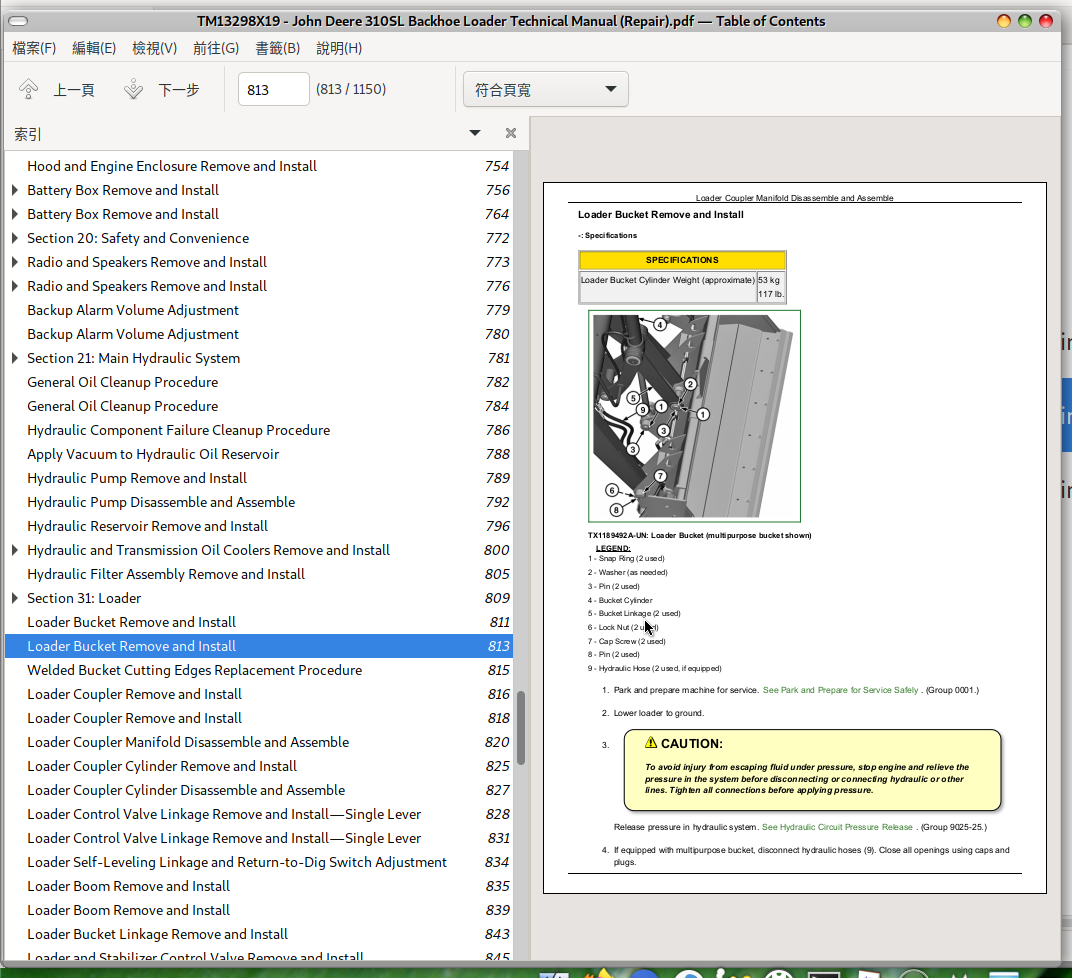
Loader Bucket Remove and Install
Welded Bucket Cutting Edges Replacement Procedure
Group 3104: Attachment Coupler
Loader Coupler Remove and Install
Loader Coupler Manifold Disassemble and Assemble
Loader Coupler Cylinder Remove and Install
Loader Coupler Cylinder Disassemble and Assemble
Group 3115: Controls Linkage
Loader Control Valve Linkage Remove and Install—Single Lever
Loader Self-Leveling Linkage and Return-to-Dig Switch Adjustment
Group 3140: Frames
Loader Boom Remove and Install
Loader Bucket Linkage Remove and Install
Group 3160: Hydraulic System
Loader and Stabilizer Control Valve Remove and Install
Loader and Stabilizer Control Valve Spool Disassemble and Assemble
Loader and Stabilizer Relief Valves Remove and Install
Loader and Stabilizer System Relief Valve Disassemble and Assemble
Loader Boom Anticavitation Check Valve Disassemble and Assemble
Loader Boom Raise and Bucket Curl Circuit Relief Valve Disassemble and Assemble
Loader Bucket Dump Circuit Relief Valve With Anticavitation Disassemble and Assemble
Loader Auxiliary Circuit Relief Valve Disassemble and Assemble—If Equipped
Loader Auxiliary Shutoff Plug Disassemble and Assemble
Loader Auxiliary Manifold Remove and Install
Loader Auxiliary Accumulator Remove and Install—If Equipped
Loader Boom Cylinder Remove and Install
Loader Bucket Cylinder Remove and Install
Loader Cylinders Disassemble and Assemble
Ride Control Valve Remove and Install
Ride Control Valve Disassemble and Assemble
Ride Control Accumulator Remove and Install
Ride Control Valve Solenoid Disassemble and Assemble
Loader Bucket Remove and Install
Loader Bucket Remove and Install
Welded Bucket Cutting Edges Replacement Procedure
Loader Coupler Remove and Install
Loader Coupler Remove and Install
Loader Coupler Manifold Disassemble and Assemble
Loader Coupler Cylinder Remove and Install
Loader Coupler Cylinder Disassemble and Assemble
Loader Control Valve Linkage Remove and Install—Single Lever
Loader Control Valve Linkage Remove and Install—Single Lever
Loader Self-Leveling Linkage and Return-to-Dig Switch Adjustment
Loader Boom Remove and Install
Loader Boom Remove and Install
Loader Bucket Linkage Remove and Install
Loader and Stabilizer Control Valve Remove and Install
Loader and Stabilizer Control Valve Remove and Install
Loader and Stabilizer Control Valve Spool Disassemble and Assemble
Stabilizer Spool Disassemble and Assemble
Boom Spool Disassemble and Assemble
Bucket Spool Disassemble and Assemble
Auxiliary Spool Disassemble and Assemble—If Equipped
Loader and Stabilizer Relief Valves Remove and Install
Loader and Stabilizer System Relief Valve Disassemble and Assemble
Loader Boom Anticavitation Check Valve Disassemble and Assemble
Loader Boom Raise and Bucket Curl Circuit Relief Valve Disassemble and Assemble
Loader Bucket Dump Circuit Relief Valve With Anticavitation Disassemble and Assemble
Loader Auxiliary Circuit Relief Valve Disassemble and Assemble—If Equipped
Loader Auxiliary Shutoff Plug Disassemble and Assemble
Loader Auxiliary Manifold Remove and Install
Loader Auxiliary Accumulator Remove and Install—If Equipped
MACHINE PREPARATION
REMOVAL
INSTALLATION
Loader Boom Cylinder Remove and Install
Loader Bucket Cylinder Remove and Install
Loader Cylinders Disassemble and Assemble
Ride Control Valve Remove and Install
Ride Control Valve Disassemble and Assemble
Ride Control Accumulator Remove and Install
Ride Control Valve Solenoid Disassemble and Assemble
Section 33: Backhoe
Group 3302: Bucket
Backhoe Bucket and Linkage Remove and Install
Backhoe Bucket Tooth Tips Remove and Install
Bucket Tooth Shank Remove and Install
Backhoe Bucket Cutting Edge Remove and Install
Group 3304: Attachment Coupler
Hydraulic Backhoe Coupler Remove and Install
Hydraulic Backhoe Coupler Disassemble and Assemble
Hydraulic Backhoe Coupler Valve Manifold Remove and Install
Hydraulic Backhoe Coupler Valve Manifold Disassemble and Assemble
Group 3315: Control Linkage
Backhoe Lever Linkage Remove and Install—Two Lever
Backhoe Lever Linkage Disassemble and Assemble—Two Lever
Backhoe Auxiliary Pedal Remove and Install—Fifth and Sixth Functions
Backhoe Auxiliary Pedal Disassemble and Assemble—Fifth and Sixth Functions
Backhoe Boom Lock Remove and Install
Backhoe Boom Lock Lever Linkage Remove and Install
Stabilizer Lever Linkage Remove and Install
Backhoe Pilot Control Valve Remove and Install
Backhoe Pilot Control Valve Disassemble and Assemble
Backhoe Pilot Control Tower Remove and Install
Backhoe Pilot Control Tower Disassemble and Assemble
Group 3340: Frames
Backhoe Boom Remove and Install
Dipperstick Remove and Install
Dipperstick Extension Remove and Install—If Equipped
Swing Frame Remove and Install
Group 3360: Hydraulic System
Backhoe Control Valve Remove and Install
Backhoe Control Valve Disassemble and Assemble
Backhoe Control Valve Spool Seals Remove and Install
Backhoe Control Valve Relief Valves Remove and Install
Backhoe Inlet Section Disassemble and Assemble
Backhoe Swing Section Disassemble and Assemble
Backhoe Boom Section Disassemble and Assemble
Backhoe Bucket Section Disassemble and Assemble
Backhoe Crowd Section Disassemble and Assemble
Backhoe Auxiliary and Extendable Dipperstick Section Disassemble and Assemble—If Equipped
Backhoe Auxiliary Selective Flow Control Section Disassemble and Assemble—If Equipped
Pilot Enable and Pattern Select (PEPS) Valve Remove and Install
Pilot Enable and Pattern Select Valve Disassemble and Assemble
Backhoe Swing Cylinder Remove and Install
Backhoe Boom Cylinder Remove and Install
Backhoe Bucket Cylinder Remove and Install
Backhoe Crowd Cylinder Remove and Install
Backhoe Extendable Dipperstick Cylinder Remove and Install
Backhoe Stabilizer Cylinder Remove and Install
Backhoe Cylinders Disassemble and Assemble
Backhoe Bucket and Linkage Remove and Install
Backhoe Bucket and Linkage Remove and Install
Backhoe Bucket Tooth Tips Remove and Install
Bucket Tooth Shank Remove and Install
Backhoe Bucket Cutting Edge Remove and Install
Hydraulic Backhoe Coupler Remove and Install
MACHINE PREPARATION
REMOVAL
INSTALLATION
Hydraulic Backhoe Coupler Remove and Install
MACHINE PREPARATION
REMOVAL
INSTALLATION
Hydraulic Backhoe Coupler Disassemble and Assemble
DISASSEMBLE
ASSEMBLE
Hydraulic Backhoe Coupler Valve Manifold Remove and Install
MACHINE PREPARATION
REMOVAL
INSTALLATION
Hydraulic Backhoe Coupler Valve Manifold Disassemble and Assemble
Backhoe Lever Linkage Remove and Install—Two Lever
Backhoe Lever Linkage Remove and Install—Two Lever
Backhoe Lever Linkage Disassemble and Assemble—Two Lever
Linkage Remove and Install
Linkage Assembly Disassemble and Assemble
Link Assembly Disassemble and Assemble
Backhoe Auxiliary Pedal Remove and Install—Fifth and Sixth Functions
Manual Controls
Pilot Controls
Backhoe Auxiliary Pedal Disassemble and Assemble—Fifth and Sixth Functions
Manual Controls
Pilot Controls
Linkage Disassemble and Assemble
Backhoe Boom Lock Remove and Install
Backhoe Boom Lock Lever Linkage Remove and Install
Manual Controls
Pilot Controls
Stabilizer Lever Linkage Remove and Install
Backhoe Pilot Control Valve Remove and Install
Backhoe Pilot Control Valve Disassemble and Assemble
Backhoe Pilot Control Valve Disassemble and Assemble (S.N. —303523)
Backhoe Pilot Control Valve Disassemble and Assemble (S.N. 303524— )
Backhoe Pilot Control Tower Remove and Install
Right Pilot Control Remove and Install
Left Pilot Control Remove and Install
Backhoe Pilot Control Tower Disassemble and Assemble
Right Pilot Control Tower Disassemble and Assemble (S.N. —303523)
Left Pilot Control Tower Disassemble and Assemble (S.N. —303523)
Right Pilot Control Tower Disassemble and Assemble (S.N. 303524— )
Left Pilot Control Tower Disassemble and Assemble (S.N. 303524— )
Backhoe Boom Remove and Install
Backhoe Boom Remove and Install
Dipperstick Remove and Install
Standard Dipperstick
Extendable Dipperstick
Dipperstick Extension Remove and Install—If Equipped
Swing Frame Remove and Install
Backhoe Control Valve Remove and Install
Manual Controls
Pilot Controls
Backhoe Control Valve Remove and Install
Manual Controls
Pilot Controls
Backhoe Control Valve Disassemble and Assemble
Backhoe Control Valve Spool Seals Remove and Install
Backhoe Control Valve Relief Valves Remove and Install
Backhoe Inlet Section Disassemble and Assemble
Inlet Section Disassemble and Assemble
System Relief Valve Disassemble and Assemble
Backhoe Swing Section Disassemble and Assemble
Backhoe Swing Section Disassemble and Assemble—Manual Controls
Backhoe Swing Section Disassemble and Assemble—Pilot Controls
Swing Circuit Relief Valve Disassemble and Assemble
Backhoe Boom Section Disassemble and Assemble
Backhoe Boom Section Disassemble and Assemble—Manual Controls
Backhoe Boom Section Disassemble and Assemble—Pilot Controls
Relief Valve Disassemble and Assemble—With Anticavitation
Relief Valve Disassemble and Assemble—No Anticavitation
Backhoe Bucket Section Disassemble and Assemble
Bucket Section Disassemble and Assemble—Manual Controls
Bucket Section Disassemble and Assemble—Pilot Controls
Relief Valve Disassemble and Assemble
Backhoe Crowd Section Disassemble and Assemble
Backhoe Crowd Section Disassemble and Assemble—Manual Controls
Backhoe Crowd Section Disassemble and Assemble—Pilot Controls
Relief Valve 22 mm (0.88 in.) Disassemble and Assemble
Relief Valve 26 mm (1 in.) Disassemble and Assemble
Backhoe Auxiliary and Extendable Dipperstick Section Disassemble and Assemble—If Equipped
Auxiliary Section Disassemble and Assemble
Relief Valve Disassemble and Assemble
Backhoe Auxiliary Selective Flow Control Section Disassemble and Assemble—If Equipped
Auxiliary Selective Flow Control Section Disassemble and Assemble
Relief Valve Disassemble and Assemble
Pilot Enable and Pattern Select (PEPS) Valve Remove and Install
Pilot Enable and Pattern Select Valve Disassemble and Assemble
Backhoe Swing Cylinder Remove and Install
REMOVAL
INSTALLATION
Backhoe Boom Cylinder Remove and Install
Backhoe Bucket Cylinder Remove and Install
Machine Preparation
Additional Information
Backhoe Crowd Cylinder Remove and Install
Backhoe Extendable Dipperstick Cylinder Remove and Install
Backhoe Stabilizer Cylinder Remove and Install
Backhoe Cylinders Disassemble and Assemble
Section 38: Grapple
Group 3800: Removal and Installation
Hydraulic Thumb Remove and Install—If Equipped
Group 3860: Hydraulic System
Hydraulic Thumb Cylinder Remove and Install—If Equipped
Hydraulic Thumb Cylinder Disassemble and Assemble—If Equipped
Hydraulic Thumb Remove and Install—If Equipped
Hydraulic Thumb Remove and Install—If Equipped
Hydraulic Thumb Cylinder Remove and Install—If Equipped
Hydraulic Thumb Cylinder Remove and Install—If Equipped
Hydraulic Thumb Cylinder Disassemble and Assemble—If Equipped
Section 99: Dealer Fabricated Tools
Group 9900: Dealer Fabricated Tools
DFT1380 Lift Bracket
DFT1285A Engine Support Bracket
DFT1286 Backlash Measurement Tool
DFT1163 MFWD Snap Ring Removal and Installation Tool
DFT1380 Lift Bracket
DFT1380 Lift Bracket
DFT1285A Engine Support Bracket
DFT1286 Backlash Measurement Tool
DFT1163 MFWD Snap Ring Removal and Installation Tool
tm13298x19 - 310SL Backhoe Loader Technical Manual MAIN SECTIONNS
Foreword
Manual Identification—READ THIS FIRST!
General Information
Safety
Torque Values
Wheels
Powered or Non-Powered Wheels and Fastenings
Axles and Suspension Systems
Input Drive Shafts and U-Joints
Non-Powered Wheel Axles
Powered Wheel Axle (MFWD)
Axle Shaft, Bearings, and Reduction Gears
Transmission
Removal and Installation
Gear, Shafts, and Power Shift Clutches
Hydraulic System
Engine
Removal and Installation
Engine Auxiliary System
Cold Weather Starting Aids
Cooling Systems
Intake System
Exhaust Systems
External Fuel Supply Systems
Torque Converter
Turbine, Gears, and Shaft
Steering System
Power Steering
Power Steering Hydraulic System
Service Brakes
Active Elements
Controls Linkage
Hydraulic System
Park Brake
Active Elements
Electrical System
Remove and Install
System Controls
Frame or Supporting Structure
Frame Installation
Chassis Weights
Operator's Station
Removal and Installation
Operator Enclosure
Seat and Seat Belt
Heating and Air Conditioning
Sheet Metal and Styling
Hood or Engine Enclosure
Miscellaneous Shields
Safety and Convenience
Radio
Horn and Warning Devices
Main Hydraulic System
Hydraulic System
Loader
Bucket
Attachment Coupler
Controls Linkage
Frames
Hydraulic System
Backhoe
Bucket
Attachment Coupler
Control Linkage
Frames
Hydraulic System
Grapple
Removal and Installation
Hydraulic System
Dealer Fabricated Tools
Dealer Fabricated Tools
John Deere 310SL Backhoe Loader Workshop Service Repair Manual (TM13298X19)


