John Deere 310SL HL & 410L Backhoe Loader Workshop Service Manual (TM13299X19)
Catalog:
Model:
John Deere 310SL HL & 410L Backhoe Loader Workshop Service Repair manual with Electrical Wiring Diagrams (including maintenance, overhaul, disassembling & assembling, adjustment, tune-up, operation, inspecting, diagnosis & troubleshooting…) is divided into different sections. Each section covers a specific component or system with detailed illustrations. A table of contents is placed at the beginning of each section. Pages are easily found by category, and each page is expandable for great detail. The printer-ready PDF documents work like a charm on all kinds of devices.
This manual contains high quality images, circuit diagrams, instructions to help you to maintenance, troubleshoot, diagnose, and repair. This document is printable, without restrictions, contains searchable text, bookmarks, crosslinks for easy navigation.
TM13299X19 (10MAY19) - John Deere 310SL HL & 410L Backhoe Loader (PIN 1T0310HL_ _F273920— ) (PIN 1T0410LX_ _F273920— ) Operation & Test Technical Manual.PDF
TM13299X19 - John Deere 310SL HL, 410L Backhoe Loader Technical Manual (Operation & Test).epub
TM13299X19 - John Deere 310SL HL, 410L Backhoe Loader Technical Manual (Operation & Test).pdf
TABLE OF CONTENTS / FILE LIST:
Foreword
Manual Identification—READ THIS FIRST!
Section 9000: General Information
Group 01: Safety
Recognize Safety Information
Follow Safety Instructions
Operate Only If Qualified
Wear Protective Equipment
Avoid Unauthorized Machine Modifications
Inspect Machine
Stay Clear of Moving Parts
Avoid High-Pressure Fluids
Avoid High-Pressure Oils
Work In Ventilated Area
Avoid Static Electricity Risk When Refueling
Prevent Fires
In Case of Machine Fire
Prevent Battery Explosions
Handle Chemical Products Safely
Exhaust Filter Ash Handling and Disposal
Prepare for Emergencies
Clean Debris from Machine
Decommissioning — Proper Recycling and Disposal of Fluids and Components
Use Steps and Handholds Correctly
Start Only From Operator's Seat
Use and Maintain Seat Belt
Prevent Unintended Machine Movement
Prevent Unintended Machine Movement—If Equipped With Pilot Controls
Avoid Work Site Hazards
Keep Riders Off Machine
Avoid Backover Accidents
Avoid Machine Tipover
Operating or Traveling On Public Roads
Inspect and Maintain ROPS
Travel Safely
Prevent Acid Burns
Add and Operate Attachments Safely
Use Special Care When Operating
Park and Prepare for Service Safely
Service Cooling System Safely
Remove Paint Before Welding or Heating
Make Welding Repairs Safely
Drive Metal Pins Safely
Follow Tire Recommendations
Service Tires Safely
Clean Exhaust Filter Safely
Recognize Safety Information
Recognize Safety Information
Follow Safety Instructions
Operate Only If Qualified
Wear Protective Equipment
Avoid Unauthorized Machine Modifications
Inspect Machine
Stay Clear of Moving Parts
Avoid High-Pressure Fluids
Avoid High-Pressure Oils
Work In Ventilated Area
Avoid Static Electricity Risk When Refueling
Prevent Fires
In Case of Machine Fire
Prevent Battery Explosions
Handle Chemical Products Safely
Exhaust Filter Ash Handling and Disposal
Prepare for Emergencies
Clean Debris from Machine
Decommissioning — Proper Recycling and Disposal of Fluids and Components
Use Steps and Handholds Correctly
Start Only From Operator's Seat
Use and Maintain Seat Belt
Prevent Unintended Machine Movement
Prevent Unintended Machine Movement—If Equipped With Pilot Controls
Avoid Work Site Hazards
Keep Riders Off Machine
Avoid Backover Accidents
Avoid Machine Tipover
Operating or Traveling On Public Roads
Inspect and Maintain ROPS
Travel Safely
Prevent Acid Burns
Add and Operate Attachments Safely
Use Special Care When Operating
Park and Prepare for Service Safely
Service Cooling System Safely
Remove Paint Before Welding or Heating
Make Welding Repairs Safely
Drive Metal Pins Safely
Follow Tire Recommendations
Service Tires Safely
Clean Exhaust Filter Safely
Section 9001: Diagnostics
Group 10: Engine Control Unit (ECU) Diagnostic Trouble Codes
Engine Control Unit (ECU) Diagnostic Trouble Codes
000029.03 - Hand Throttle
000029.04 - Hand Throttle
000029.14 - Hand Throttle
000091.03 - Foot Throttle
000091.04 - Foot Throttle
000091.14 - Foot Throttle
000237.02 - Vehicle ID
000237.13 - Vehicle ID
000237.31 - Vehicle ID
000647.05 - Engine Fan Driver
000647.06 - Engine Fan Driver
001321.05 - Starter Relay
001321.06 - Starter Relay
001321.09 - Starter Relay
001321.16 - Starter Relay
001321.31 - Starter Relay
001639.01 - Fan Speed
001761.01 - DEF LEVEL
001761.18 - DEF LEVEL
002003.09 - No CAN From TCU
002071.09 - No CAN From VCU
003031.12 - DEF Temperature
003353.31 - Alternator Output
003516.01 - Diesel Exhaust Fluid Concentration Extremely Low
003516.07 - Diesel Exhaust Fluid Concentration Invalid
003516.09 - Diesel Exhaust Fluid Tank Header Communication Fault
003516.12 - Diesel Exhaust Fluid Concentration Sensor Fault
003517.12 - Diesel Exhaust Fluid Tank Level Sensor Fault
004366.05 - DEF Tank Heater Coolant Control Valve Circuit Has High Resistance
004366.06 - DEF Tank Heater Coolant Control Valve Circuit Has Low Resistance
004366.16 - DEF Tank Temperature Moderately High
004366.18 - DEF Tank Insufficient Heating Fault
005927.05 - Coolant Pump
005927.06 - Coolant Pump
005927.07 - Coolant Pump
524225.31 - Engine Start
Group 20: Standard Display Monitor (SDM) Diagnostic Trouble Codes
Standard Display Monitor (SDM) Diagnostic Trouble Codes
000096.03 - Fuel Level Sensor
000096.04 - Fuel Level Sensor
000168.03 - Battery Voltage
000237.02 - Vehicle ID
000237.13 - Vehicle ID
000237.31 - Vehicle ID
000628.12 - Programming
000629.12 - Controller Fault
000920.12 - Alarm Output
001196.11 - Security
002000.09 - No CAN from ECU
002003.09 - No CAN from TCU
002071.09 - No CAN from VCU
002072.09 - System Message
002251.09 - No CAN from MTG
003509.03 - Sensor Supply 1
003509.04 - Sensor Supply 1
524082.07 - Display Buttons
Group 30: Transmission Control Unit (TCU) Diagnostic Trouble Codes
Transmission Control Unit (TCU) Diagnostic Trouble Codes
000070.14 - Park Brake
000177.00 - Trans Oil Temp
000177.04 - Trans Oil Temp
000191.03 - Transmission Speed
000191.04 - Transmission Speed
000525.02 - Requested Gear
000525.03 - Requested Gear
000525.05 - Requested Gear
000629.12 - Controller Fault
000734.03 - Y1 Solenoid
000734.04 - Y1 Solenoid
000734.05 - Y1 Solenoid
000734.06 - Y1 Solenoid
000735.03 - Y2 Solenoid
000735.04 - Y2 Solenoid
000735.05 - Y2 Solenoid
000735.06 - Y2 Solenoid
000736.03 - Y3 Solenoid
000736.05 - Y3 Solenoid
000736.06 - Y3 Solenoid
000737.03 - Y4 Solenoid
000737.05 - Y4 Solenoid
000737.06 - Y4 Solenoid
000738.03 - Y5 Solenoid
000738.05 - Y5 Solenoid
000738.06 - Y5 Solenoid
000739.03 - Y6 Solenoid
000739.05 - Y6 Solenoid
000739.06 - Y6 Solenoid
000746.03 - Differential Lock
000746.05 - Differential Lock
000746.06 - Differential Lock
000880.03 - Brake Lights
000880.05 - Brake Lights
000880.06 - Brake Lights
002000.09 - System Message
002023.09 - System Message
002071.09 - System Message
002072.09 - System Message
002392.03 - Reverse Alarm
002392.06 - Reverse Alarm
002612.03 - MFWD Solenoid
002612.05 - MFWD Solenoid
002612.06 - MFWD Solenoid
522379.03 - Park Brake
522379.04 - Park Brake
522379.05 - Park Brake
522379.06 - Park Brake
522411.02 - TCL Selector
522411.03 - TCL Selector
522411.05 - TCL Selector
524172.03 - Clutch Disconnect
Group 40: Vehicle Control Unit (VCU) Diagnostic Trouble Codes
Vehicle Control Unit (VCU) Diagnostic Trouble Codes
000168.03 - Battery Voltage
000237.02 - Vehicle ID
000237.13 - Vehicle ID
000237.31 - Vehicle ID
000628.12 - Programming
000629.12 - Control Unit
001321.16 - Starter Relay
001638.00 - HYD OIL TEMP
001638.04 - HYD OIL TEMP
001638.16 - HYD OIL TEMP
001713.00 - Hyd Oil Restriction
002142.09 - System Message
002228.12 - EH Watchdog
002347.03 - Front Light Switch
002347.04 - Front Light Switch
002354.06 - Front Work Lights
002356.06 - Front Work Lights
002360.06 - Rear Work Lights
002362.06 - Rear Work Lights
002366.06 - Side Work Lights
002368.03 - Left Flasher
002368.05 - Left Flasher
002368.06 - Left Flasher
002370.03 - Right Flasher
002370.05 - Right Flasher
002370.06 - Right Flasher
002378.03 - Marker Light
002378.05 - Marker Light
002378.06 - Marker Light
002863.02 - Wiper Switch
002876.04 - Turn Signal Switch
003509.03 - Sensor Supply 1
003509.04 - Sensor Supply 1
003510.03 - Sensor Supply 2
003510.04 - Sensor Supply 2
003997.03 - Accessory Relay
003997.05 - Accessory Relay
003997.06 - Accessory Relay
004086.03 - Valve LS Pressure
004086.04 - Valve LS Pressure
004086.14 - Valve LS Pressure
004088.03 - Pump LS Pressure
004088.04 - Pump LS Pressure
004089.03 - Pump Out Pressure
004089.04 - Pump Out Pressure
516859.14 - Pump Control
516860.14 - Pump Margin Pressure
517120.03 - Loader Boom Rod Press
517120.04 - Loader Boom Rod Press
520416.05 - Valve Power
520546.07 - Pilot Enable Switch
520688.03 - Pilot Enable Driver
520688.05 - Pilot Enable Driver
520688.06 - Pilot Enable Driver
520696.03 - Pattern Select Driver
520696.05 - Pattern Select Driver
520696.06 - Pattern Select Driver
520713.03 - Seat Position
520713.04 - Seat Position
520713.13 - Seat Position
522312.03 - Front Washer
522312.05 - Front Washer
522312.06 - Front Washer
522426.03 - Rear Wiper Park
522426.04 - Rear Wiper Park
522427.03 - Front Wiper Park
522427.04 - Front Wiper Park
522433.03 - Rear Wiper
522433.05 - Rear Wiper
522433.06 - Rear Wiper
522434.03 - Front Wiper Low
522434.05 - Front Wiper Low
522434.06 - Front Wiper Low
522435.03 - Front Wiper High
522435.05 - Front Wiper High
522435.06 - Front Wiper High
523307.03 - Crank Signal
523307.04 - Crank Signal
523911.03 - Pump Control
523911.04 - Pump Control
523911.05 - Pump Control
523911.06 - Pump Control
523911.13 - Pump Control
523911.16 - Pump Control
523911.18 - Pump Control
523948.03 - Ride Control
523948.05 - Ride Control
523948.06 - Ride Control
Group 50: Auxiliary Valve Controller (AVC) Diagnostic Trouble Codes
Auxiliary Valve Controller (AVC) Diagnostic Trouble Codes
000168.03 - Battery Voltage
000237.02 - Vehicle ID
000237.13 - Vehicle ID
000237.31 - Vehicle ID
000629.12 - Control Unit
002701.03 - BH Aux Roller
002701.04 - BH Aux Roller
002701.07 - BH Aux Roller
002738.03 - Extendable Roller
002738.04 - Extendable Roller
002738.07 - Extendable Roller
517276.03 - Loader Coupler
517276.05 - Loader Coupler
517276.06 - Loader Coupler
520425.07 - System Message
520426.07 - System Message
520542.03 - System Message
520543.04 - System Message
520697.03 - Loader Coupler Press
520697.05 - Loader Coupler Press
520697.06 - Loader Coupler Press
522438.03 - Loader Coupler
522438.05 - Loader Coupler
522438.06 - Loader Coupler
523934.00 - Extendable Sol A
523934.01 - Extendable Sol A
523934.03 - Extendable Sol A
523934.04 - Extendable Sol A
523934.05 - Extendable Sol A
523934.06 - Extendable Sol A
523940.00 - Extendable Sol B
523940.01 - Extendable Sol B
523940.03 - Extendable Sol B
523940.04 - Extendable Sol B
523940.05 - Extendable Sol B
523940.06 - Extendable Sol B
524010.00 - Selective Flow
524010.01 - Selective Flow
524010.03 - Selective Flow
524010.04 - Selective Flow
524010.05 - Selective Flow
524010.06 - Selective Flow
Group 60: Sealed Switch Module (SSM) Diagnostic Trouble Codes
Sealed Switch Module (SSM) Diagnostic Trouble Codes
002033.09 - System Message
002634.04 - Ignition Relay Circuit Fault
002634.05 - Ignition Relay Circuit Fault
521274.09 - System Message
523850.04 - SSM Button Stuck
523850.09 - System Message
523852.04 - SSM Button Stuck
523852.09 - System Message
523854.04 - SSM Button Stuck
523854.09 - System Message
523855.04 - SSM Button Stuck
523855.09 - System Message
523856.04 - SSM Button Stuck
523856.09 - System Message
523857.04 - SSM Button Stuck
523857.09 - System Message
523858.04 - SSM Button Stuck
523858.09 - System Message
523860.04 - SSM Button Stuck
523860.09 - System Message
523861.04 - SSM Button Stuck
523861.09 - System Message
523862.04 - SSM Button Stuck
523862.09 - System Message
523863.04 - SSM Button Stuck
523863.09 - System Message
523864.04 - SSM Button Stuck
523864.09 - System Message
523865.04 - SSM Button Stuck
523865.09 - System Message
523867.04 - SSM Button Stuck
523867.09 - System Message
523868.04 - SSM Button Stuck
523868.09 - System Message
Group 70: Vehicle Control Unit 2 (VC2) Diagnostic Trouble Codes
Vehicle Control Unit 2 (VC2) Diagnostic Trouble Codes
002664.03 - Ldr Aux Roller
002664.04 - Ldr Aux Roller
002664.07 - Ldr Aux Roller
003509.03 - SENSOR SUPPLY 1
003509.04 - SENSOR SUPPLY 1
520669.00 - Loader Aux Pressure
520669.01 - Loader Aux Pressure
520669.03 - Loader Aux Sol A
520669.04 - Loader Aux Sol A
520669.05 - Loader Aux Sol A
520669.06 - Loader Aux Sol A
520687.03 - Backhoe Coupler
520687.05 - Backhoe Coupler
520687.06 - Backhoe Coupler
523404.00 - Backhoe Aux Pressure
523404.01 - Backhoe Aux Pressure
523935.03 - Backhoe Aux Sol A
523935.04 - Backhoe Aux Sol A
523935.05 - Backhoe Aux Sol A
523935.06 - Backhoe Aux Sol A
Engine Control Unit (ECU) Diagnostic Trouble Codes
Engine Control Unit (ECU) Diagnostic Trouble Codes
Standard Display Monitor (SDM) Diagnostic Trouble Codes
Standard Display Monitor (SDM) Diagnostic Trouble Codes
Transmission Control Unit (TCU) Diagnostic Trouble Codes
Transmission Control Unit (TCU) Diagnostic Trouble Codes
Vehicle Control Unit (VCU) Diagnostic Trouble Codes
Vehicle Control Unit (VCU) Diagnostic Trouble Codes
Auxiliary Valve Controller (AVC) Diagnostic Trouble Codes
Auxiliary Valve Controller (AVC) Diagnostic Trouble Codes
Sealed Switch Module (SSM) Diagnostic Trouble Codes
Sealed Switch Module (SSM) Diagnostic Trouble Codes
Vehicle Control Unit 2 (VC2) Diagnostic Trouble Codes
Vehicle Control Unit 2 (VC2) Diagnostic Trouble Codes
Section 9005: Operational Checkout Procedure
Group 10: Operational Checkout Procedure
Operational Checkout Procedure
Operational Checkout Procedure
Operational Checkout Procedure
Section 9010: Engine
Group 05: Theory of Operation
John Deere Engine Operation
Engine Cooling System Operation
Cold Start Aid System Operation
Group 10: System Diagrams
Engine Intake and Exhaust Component Location
Engine Fuel System Component Location
Engine Cooling System Component Location
Group 15: Diagnostic Information
John Deere Engine Operation
Engine Identification
Engine Cooling Fan Continuously Runs at Engine Speed
Group 20: Adjustments
John Deere Engine Operation
Service Filter Cleaning
Group 25: Tests
John Deere Engine Operation
Fluid Sampling Procedure
Air in Fuel Test
Engine Speed Check
Engine Thermostat Test
Thermal Bypass Valve Test
Diesel Exhaust Fluid (DEF) Cooling System Test
John Deere Engine Operation
John Deere Engine Operation
Engine Cooling System Operation
Cold Start Aid System Operation
Air Intake Heater—Engines 4045HT082 and 4045HT096
Glow Plugs—Engines 4045HT083 and 4045HT084
Engine Intake and Exhaust Component Location
Engine Intake and Exhaust Component Location (S.N. —303523)
Engine Intake and Exhaust Component Location (S.N. 303524—307116)
Engine Intake and Exhaust Component Location (S.N. 307117— )
Engine Intake and Exhaust Component Location
Engine Intake and Exhaust Component Location (S.N. —303523)
Engine Intake and Exhaust Component Location (S.N. 303524—307116)
Engine Intake and Exhaust Component Location (S.N. 307117— )
Engine Fuel System Component Location
Engine Cooling System Component Location
Engine Cooling System Component Location (S.N. —303523)
Engine Cooling System Component Location (S.N. 303524—307116)
Engine Cooling System Component Location (S.N. 307117— )
John Deere Engine Operation
John Deere Engine Operation
Engine Identification
Engine Serial and Model Number Identification
Engine Component Identification
John Deere Engine Operation
John Deere Engine Operation
Service Filter Cleaning
John Deere Engine Operation
John Deere Engine Operation
Fluid Sampling Procedure
Machine Preparation
Priming Sample Valve
Obtaining Fluid Sample
Air in Fuel Test
Engine Speed Check
Engine Thermostat Test
Thermal Bypass Valve Test
Diesel Exhaust Fluid (DEF) Cooling System Test
Diesel Exhaust Fluid (DEF) Cooling System Test (S.N. —303523)
Diesel Exhaust Fluid (DEF) Cooling System Test (S.N. 303524—307116)
Section 9015: Electrical System
Group 05: Theory of Operation
Controller Area Network (CAN) Circuit Theory of Operation
Local Interconnect Network (LIN) Circuit Theory of Operation
Engine Control Unit (ECU) Circuit Theory of Operation
Vehicle Control Unit (VCU) Circuit Theory of Operation
Standard Display Monitor (SDM) Circuit Theory of Operation
Start and Charge Circuit Theory of Operation
Hydraulic System Circuit Theory of Operation
Transmission Control Circuit Theory of Operation
Exhaust Aftertreatment Circuit Theory of Operation
Auxiliary Valve Controller (AVC) Circuit Theory of Operation
Horn, Lights, and Beacon Circuit Theory of Operation
Wiper and Washer Circuit Theory of Operation
JDLink™ Circuit Theory of Operation
Group 10: System Diagrams
Electrical Diagram Information
Electrical Schematic Symbols
System Functional Schematic and Section Legend
System Functional Schematic, Wiring Diagram, and Component Location Legend
Fuse and Relay Location and Specifications
Horn and Coolant Level Harness (W7) Wiring Diagram
Horn and Coolant Level Harness (W7) Component Location
Air Intake Heater Harness (W8) Wiring Diagram (S.N. 292654— )
Air Intake Heater Harness (W8) Component Location (S.N. 292654— )
Glow Plug Harness (W9) Wiring Diagram (S.N. —292661)
Glow Plug Harness (W9) Component Location (S.N. —292661)
Engine Harness (W10) Wiring Diagram
Engine Harness (W10) Component Location
Engine Interface Harness (W11) Wiring Diagram
Engine Interface Harness (W11) Component Location
Transmission Harness (W13) Wiring Diagram
Transmission Harness (W13) Component Location
Cab Harness (W14) Wiring Diagram
Cab Harness (W14) Component Location
Canopy Harness (W15) Wiring Diagram
Canopy Harness (W15) Component Location
Roof Harness (W17) Wiring Diagram
Roof Harness (W17) Component Location
Heater and Air Conditioner Harness (W19) Wiring Diagram
Heater and Air Conditioner Harness (W19) Component Location
Auxiliary Valve Control Harness (W23) Wiring Diagram
Auxiliary Valve Control Harness (W23) Component Location
Loader Coupler Solenoid Harness (W26) Wiring Diagram
Loader Coupler Solenoid Harness (W26) Component Location
Ride Control Solenoid Harness (W27) Wiring Diagram
Ride Control Solenoid Harness (W27) Component Location
Selective Flow Solenoid Harness (W28) Wiring Diagram
Selective Flow Solenoid Harness (W28) Component Location
Loader Auxiliary Solenoid Harness (W29) Wiring Diagram
Loader Auxiliary Solenoid Harness (W29) Component Location
Pilot Enable Pattern Select Valve Harness (W30) Wiring Diagram
Pilot Enable Pattern Select Valve Harness (W30) Component Location
Pilot Enable Switch Harness (W31) Wiring Diagram
Pilot Enable Switch Harness (W31) Component Location
Return-to-Dig Harness (W32) Wiring Diagram
Return-to-Dig Harness (W32) Component Location
Air Conditioner Compressor Clutch Harness (W39) Wiring Diagram
Air Conditioner Compressor Clutch Harness (W39) Component Location
Pilot Control and Selective Flow Harness (W41) Wiring Diagram
Pilot Control and Selective Flow Harness (W41) Component Location
Extendable Dipperstick Harness (W45) Wiring Diagram
Extendable Dipperstick Harness (W45) Component Location
Backhoe Auxiliary Harness (W46) Wiring Diagram
Backhoe Auxiliary Harness (W46) Component Location
Auxiliary Hydraulic Foot Switch Harness (W47) Wiring Diagram—If Equipped
Auxiliary Hydraulic Foot Switch Harness (W47) Component Location—If Equipped
Variable Speed Fan Harness (W48) Wiring Diagram
Variable Speed Fan Harness (W48) Component Location
Diesel Exhaust Fluid (DEF) Harness (W49) Wiring Diagram
Diesel Exhaust Fluid (DEF) Harness (W49) Component Location
Aftertreatment Harness (W50) Wiring Diagram
Aftertreatment Harness (W50) Component Location
Radio Harnesses (W51, W52, W53, and W54) Wiring Diagrams
Radio Harnesses (W51, W52, W53, W54, and W55) Component Location
Blower Mode Door Motor Harness (W56) Wiring Diagram
Blower Mode Door Motor Harness (W56) Component Location
Fuel Injector Harness (W57) Wiring Diagram
Fuel Injector Harness (W57) Component Location
Coolant Control Valve (CCV) Harness (W59) Wiring Diagram (S.N. 303524— )
Coolant Control Valve (CCV) Harness (W59) Component Location (S.N. 303524— )
Loader Cylinder Pressure Sensor Harness 1 (W60) Wiring Diagram (S.N. 303524— )
Loader Cylinder Pressure Sensor Harness 1 (W60) Component Location (S.N. 303524— )
Loader Cylinder Pressure Sensor Harness 2 (W61) Wiring Diagram (S.N. 303524— )
Loader Cylinder Pressure Sensor Harness 2 (W61) Component Location (S.N. 303524— )
Loader and Backhoe Coupler Harness (W62) Wiring Diagram—If Equipped
Loader and Backhoe Coupler Harness (W62) Component Location—If Equipped
Modular Telematics Gateway (MTG) Harness (W6002) Wiring Diagram
Modular Telematics Gateway (MTG) Harness (W6002) Component Location
Satellite (SAT) Harness (W6003) Wiring Diagram
Satellite (SAT) Harness (W6003) Component Location
Group 15: Diagnostic Information
Electrical Component Specifications
Service ADVISOR™ Diagnostic Application
Service ADVISOR™ Connection Procedure
Reading Diagnostic Trouble Codes (DTCs) With Service ADVISOR™ Diagnostic Application
Intermittent Diagnostic Trouble Code (DTC) Diagnostics
Using Service ADVISOR™ Remote
JDLink™ Connection Procedure
Group 16: Monitor Operation
Service Mode
Operation—Exhaust Filter Service Cleaning
Operation—Software Delivery
Diagnostics—Clear Stored Diagnostic Trouble Codes (DTCs)
Diagnostics—Engine
Diagnostics—Electrical, Lights
Diagnostics—Transmission
Diagnostics—Hydraulics
Diagnostics—Buttons
Diagnostics—Service Advisor
Diagnostics—Sensors
Setup—Monitor
Setup—Auto-Idle
Setup—Auto-Shutdown
Setup—Calibrations
Setup—Hydraulics
Setup—Ignition Shutdown
Setup—High Altitude Mode
Setup—Transmission
Group 17: Diagnostic Test Box
Setup and Functional Test
Two Wire Sensor Circuit Check—Out of Range High
Two Wire Sensor Circuit Check—Out of Range Low
Three Wire Sensor Circuit Check—Out of Range High
Three Wire Sensor Circuit Check—Out of Range Low
Group 20: Adjustments
Load Sense Generation Valve Calibration
Auxiliary Selective Flow Control Valve Calibration—If Equipped
Backhoe Auxiliary Calibration—If Equipped
Loader Auxiliary Calibration—If Equipped
Extendable Dipperstick Calibration—If Equipped
Group 25: Tests
CAN Circuit Test
Controller Area Network (CAN) Resistor Test
Auxiliary Selective Flow Control Circuit Test
Throttle Position Sensor Test
Alternator Test
Relay Test
Wire Harness Test
Sensor Circuit Test
Engine Speed Control Pedal Test
Controller Area Network (CAN) Circuit Theory of Operation
Controller Area Network (CAN) Circuit Theory of Operation
Local Interconnect Network (LIN) Circuit Theory of Operation
Engine Control Unit (ECU) Circuit Theory of Operation
Vehicle Control Unit (VCU) Circuit Theory of Operation
Standard Display Monitor (SDM) Circuit Theory of Operation
Start and Charge Circuit Theory of Operation
Start and Charge Circuit Theory of Operation (Engines 4045HT082, 4045HT083, and 4045HT096)
Hydraulic System Circuit Theory of Operation
Transmission Control Circuit Theory of Operation
Exhaust Aftertreatment Circuit Theory of Operation
Diesel Exhaust Fluid (DEF) System (S.N. —303523)
Diesel Exhaust Fluid (DEF) System (S.N. 303524— )
Auxiliary Valve Controller (AVC) Circuit Theory of Operation
If Equipped
Horn, Lights, and Beacon Circuit Theory of Operation
Wiper and Washer Circuit Theory of Operation
Wiper and Washer Circuit Theory of Operation (S.N. —303523)
Wiper and Washer Circuit Theory of Operation (S.N. 303524— )
JDLink™ Circuit Theory of Operation
Electrical Diagram Information
System Functional Schematic Diagram
Wiring Diagram
Component Location Diagram
Connector End View Diagram
Electrical Diagram Information
System Functional Schematic Diagram
Wiring Diagram
Component Location Diagram
Connector End View Diagram
Electrical Schematic Symbols
System Functional Schematic and Section Legend
System Functional Schematic, Wiring Diagram, and Component Location Legend
Fuse and Relay Location and Specifications
Fuse Panel (S.N. —303523)
Fuse Panel (S.N. 303524— )
Fuse Panel Location
Engine Fuses
Switched Power Relay and Accessory Relay
Blower Motor Fuse
Main, Vehicle Control Unit (VCU), Operator’s Station, Accessory Relay, and Start Relay Fuses
Horn and Coolant Level Harness (W7) Wiring Diagram
(S.N. —303523)
(S.N. 303524—307116)
(S.N. 307117— )
Horn and Coolant Level Harness (W7) Component Location
Air Intake Heater Harness (W8) Wiring Diagram (S.N. 292654— )
Air Intake Heater Harness (W8) Component Location (S.N. 292654— )
Glow Plug Harness (W9) Wiring Diagram (S.N. —292661)
Glow Plug Harness (W9) Component Location (S.N. —292661)
Engine Harness (W10) Wiring Diagram
Engine Harness (W10) Wiring Diagram (S.N. —303523)
Engine Harness (W10) Wiring Diagram (S.N. 303524— )
Engine Harness (W10) Component Location
Engine Harness (W10) Component Location (S.N. —303523)
Engine Harness (W10) Component Location (S.N. 303524— )
Engine Interface Harness (W11) Wiring Diagram
Engine Interface Harness (W11) Component Location
Transmission Harness (W13) Wiring Diagram
Transmission Harness (W13) Component Location
Cab Harness (W14) Wiring Diagram
Cab Harness (W14) Wiring Diagram (S.N. —303523)
Cab Harness (W14) Wiring Diagram (S.N. 303524— )
Cab Harness (W14) Component Location
Cab Harness (W14) Component Location (S.N. —303523)
Cab Harness (W14) Component Location (S.N. 303524— )
Canopy Harness (W15) Wiring Diagram
Canopy Harness (W15) Wiring Diagram (S.N. —303523)
Canopy Harness (W15) Wiring Diagram (S.N. 303524— )
Canopy Harness (W15) Component Location
Canopy Harness (W15) Component Location (S.N. —303523)
Canopy Harness (W15) Component Location (S.N. 303524— )
Roof Harness (W17) Wiring Diagram
Roof Harness (W17) Component Location
Heater and Air Conditioner Harness (W19) Wiring Diagram
Heater and Air Conditioner Harness (W19) Component Location
Auxiliary Valve Control Harness (W23) Wiring Diagram
Auxiliary Valve Control Harness (W23) Component Location
Loader Coupler Solenoid Harness (W26) Wiring Diagram
Loader Coupler Solenoid Harness (W26) Wiring Diagram (S.N. —303523)
Loader Coupler Solenoid Harness (W26) Wiring Diagram (S.N. 303524— )
Loader Coupler Solenoid Harness (W26) Component Location
Loader Coupler Solenoid Harness (W26) Component Location (S.N. —303523)
Loader Coupler Solenoid Harness (W26) Component Location (S.N. 303524— )
Ride Control Solenoid Harness (W27) Wiring Diagram
Ride Control Solenoid Harness (W27) Component Location
Selective Flow Solenoid Harness (W28) Wiring Diagram
Selective Flow Solenoid Harness (W28) Component Location
Loader Auxiliary Solenoid Harness (W29) Wiring Diagram
Loader Auxiliary Solenoid Harness (W29) Component Location
Pilot Enable Pattern Select Valve Harness (W30) Wiring Diagram
Pilot Enable Pattern Select Valve Harness (W30) Component Location
Pilot Enable Switch Harness (W31) Wiring Diagram
Pilot Enable Switch Harness (W31) Component Location
Return-to-Dig Harness (W32) Wiring Diagram
Return-to-Dig Harness (W32) Component Location
Air Conditioner Compressor Clutch Harness (W39) Wiring Diagram
Air Conditioner Compressor Clutch Harness (W39) Component Location
Pilot Control and Selective Flow Harness (W41) Wiring Diagram
Pilot Control and Selective Flow Harness (W41) Component Location
Extendable Dipperstick Harness (W45) Wiring Diagram
Extendable Dipperstick Harness (W45) Component Location
Backhoe Auxiliary Harness (W46) Wiring Diagram
Backhoe Auxiliary Harness (W46) Component Location
Auxiliary Hydraulic Foot Switch Harness (W47) Wiring Diagram—If Equipped
Auxiliary Hydraulic Foot Switch Harness (W47) Component Location—If Equipped
Variable Speed Fan Harness (W48) Wiring Diagram
Variable Speed Fan Harness (W48) Wiring Diagram (S.N. —303523)
Variable Speed Fan Harness (W48) Wiring Diagram (S.N. 303524— )
Variable Speed Fan Harness (W48) Component Location
Variable Speed Fan Harness (W48) Component Location (S.N. —303523)
Variable Speed Fan Harness (W48) Component Location (S.N. 303524— )
Diesel Exhaust Fluid (DEF) Harness (W49) Wiring Diagram
Diesel Exhaust Fluid (DEF) Harness (W49) Wiring Diagram (S.N. —303523)
Diesel Exhaust Fluid (DEF) Harness (W49) Wiring Diagram (S.N. 303524— )
Diesel Exhaust Fluid (DEF) Harness (W49) Component Location
Diesel Exhaust Fluid (DEF) Harness (W49) Component Location (S.N. —303523)
Diesel Exhaust Fluid (DEF) Harness (W49) Component Location (S.N. 303524— )
Aftertreatment Harness (W50) Wiring Diagram
(S.N. —292661)
(S.N. 292654— )
Aftertreatment Harness (W50) Component Location
Radio Harnesses (W51, W52, W53, and W54) Wiring Diagrams
Satellite Radio Module Harness (W51) Wiring Diagram
Auxiliary Radio Input Harness (W52) Wiring Diagram
Radio Harness (W53) Wiring Diagram—Satellite (If Equipped)
Radio Harness (W54) Wiring Diagram—Standard (If Equipped)
Radio Harnesses (W51, W52, W53, W54, and W55) Component Location
Radio Harness (W54) Component Location—Standard (If Equipped)
Radio Harness (W53) Component Location—Satellite (If Equipped)
Blower Mode Door Motor Harness (W56) Wiring Diagram
Blower Mode Door Motor Harness (W56) Component Location
Fuel Injector Harness (W57) Wiring Diagram
Fuel Injector Harness (W57) Component Location
Coolant Control Valve (CCV) Harness (W59) Wiring Diagram (S.N. 303524— )
Coolant Control Valve (CCV) Harness (W59) Component Location (S.N. 303524— )
Loader Cylinder Pressure Sensor Harness 1 (W60) Wiring Diagram (S.N. 303524— )
Loader Cylinder Pressure Sensor Harness 1 (W60) Component Location (S.N. 303524— )
Loader Cylinder Pressure Sensor Harness 2 (W61) Wiring Diagram (S.N. 303524— )
Loader Cylinder Pressure Sensor Harness 2 (W61) Component Location (S.N. 303524— )
Loader and Backhoe Coupler Harness (W62) Wiring Diagram—If Equipped
Loader and Backhoe Coupler Harness (W62) Component Location—If Equipped
Modular Telematics Gateway (MTG) Harness (W6002) Wiring Diagram
Modular Telematics Gateway (MTG) Harness (W6002) Wiring Diagram—If Equipped With SAT
Modular Telematics Gateway (MTG) Harness (W6002) Wiring Diagram—Without SAT
Modular Telematics Gateway (MTG) Harness (W6002) Component Location
Modular Telematics Gateway (MTG) Harness Component Location—If Equipped With SAT
Modular Telematics Gateway (MTG) Harness (W6002) Component Location—Without SAT
Satellite (SAT) Harness (W6003) Wiring Diagram
Satellite (SAT) Harness (W6003) Component Location
Electrical Component Specifications
Electrical Component Specifications
Service ADVISOR™ Diagnostic Application
Service ADVISOR™ Connection Procedure
Reading Diagnostic Trouble Codes (DTCs) With Service ADVISOR™ Diagnostic Application
Intermittent Diagnostic Trouble Code (DTC) Diagnostics
Using Service ADVISOR™ Remote
Service ADVISOR™ Remote (SAR) Connection Procedure
JDLink™ Connection Procedure
Service Mode
To enter service mode:
Service Mode
To enter service mode:
Operation—Exhaust Filter Service Cleaning
Service Cleaning
Operation—Software Delivery
Diagnostics—Clear Stored Diagnostic Trouble Codes (DTCs)
Diagnostics—Engine
Diagnostics—Electrical, Lights
Diagnostics—Transmission
Diagnostics—Hydraulics
SWITCHES
PRESSURES
VALVE DATA
JOYSTICKS
PILOT ENABLE
RIDE CONTROL
HYD PUMP CONTROL
PATTERN SELECT
LOADER COUPLER
BACKHOE COUPLER
Diagnostics—Buttons
Diagnostics—Service Advisor
Diagnostics—Sensors
Setup—Monitor
Setup—Auto-Idle
Setup—Auto-Shutdown
Setup—Calibrations
Setup—Hydraulics
Setup—Ignition Shutdown
Setup—High Altitude Mode
Setup—Transmission
Setup and Functional Test
Diagnostic Test Box—Overview and Functionality
Before Connecting JDG10273 Diagnostic Test Box
JDG10273 Diagnostic Test Box—User Instructions
JDG10273 Diagnostic Test Box—Operational Test Procedure
Test Leads
Setup and Functional Test
Diagnostic Test Box—Overview and Functionality
Before Connecting JDG10273 Diagnostic Test Box
JDG10273 Diagnostic Test Box—User Instructions
JDG10273 Diagnostic Test Box—Operational Test Procedure
Test Leads
Two Wire Sensor Circuit Check—Out of Range High
Two Wire Sensor Circuit Check—Out of Range Low
Three Wire Sensor Circuit Check—Out of Range High
Three Wire Sensor Circuit Check—Out of Range Low
Load Sense Generation Valve Calibration
Load Sense Generation Valve Calibration
Auxiliary Selective Flow Control Valve Calibration—If Equipped
Backhoe Auxiliary Calibration—If Equipped
Loader Auxiliary Calibration—If Equipped
Extendable Dipperstick Calibration—If Equipped
CAN Circuit Test
Controller Area Network (CAN) Circuit Schematic (310L and 310L EP)
Controller Area Network (CAN) Circuit Schematic (310SL, 315SL, 325SL, 310SL HL, 410L, and 710L)
Engine Controller Area Network (CAN) and Aftertreatment CAN Theory of Operation Schematic (4045HT082, 4045HT083, 4045HT084, and 4045HT096 engines)
Generic CAN Circuit Schematic
Controller Area Network (CAN) Resistor Test
Auxiliary Selective Flow Control Circuit Test
Foot Switch Circuit Test
Solenoid Circuit Test
Throttle Position Sensor Test
Alternator Test
Relay Test
Wire Harness Test
Sensor Circuit Test
Engine Speed Control Pedal Test
Section 9020: Power Train
Group 05: Theory of Operation
Power Train Overview
Transmission Pump Operation
Torque Converter Operation
Clutch Modulation Operation
Clutch Pack Operation
Clutch Engagement and Solenoid Activation
Transmission Gear Flow
Differential Operation
Differential Lock Operation
Mechanical Front Wheel Drive (MFWD) Operation—If Equipped
Mechanical Front Wheel Drive (MFWD) Differential Operation—If Equipped
Park Brake Operation
Power Boost Service Brake Valve Operation
Service Brake Operation
Transmission Filter Operation
Thermal Bypass Valve Operation
Group 10: System Diagrams
Power Train Component Location
Power Train Schematic—First Forward
Power Train Schematic—Neutral
Group 15: Diagnostic Information
Diagnose Transmission Malfunctions
Transmission Overheats
Transmission Slippage
Excessive Power Train Noise
No Differential Lock Operation
Differential Lock Slips or Chatters When Engaged
Differential Lock Will Not Release
Machine Lacks Power or Moves Slow
No Power to Mechanical Front Wheel Drive (MFWD)
No Power to One Wheel of Mechanical Front Wheel Drive (MFWD)
Park Brake Will Not Hold
Park Brake Will Not Release
Poor Service Brakes
Brake Pedal Hard to Push
Service Brakes Chatter or Noisy
Service Brakes Will Not Release
Rear Axle Overfilled With Oil
Group 20: Adjustments
Mechanical Park Brake Release—Towing
Service Brake Bleed Procedure
Service Brake Pedal Adjustment
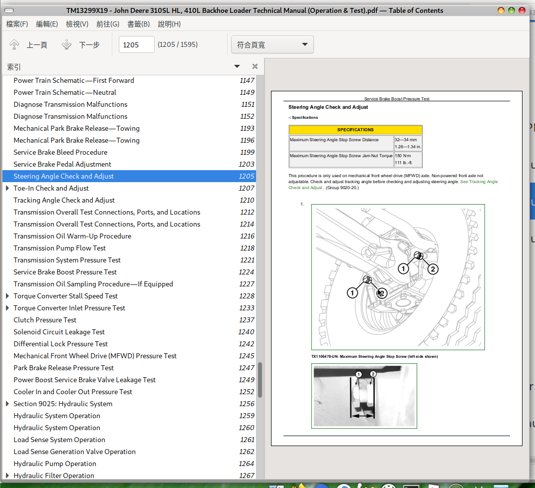
Steering Angle Check and Adjust
Toe-In Check and Adjust
Tracking Angle Check and Adjust
Group 25: Tests
Transmission Overall Test Connections, Ports, and Locations
Transmission Oil Warm-Up Procedure
Transmission Pump Flow Test
Transmission System Pressure Test
Service Brake Boost Pressure Test
Transmission Oil Sampling Procedure—If Equipped
Torque Converter Stall Speed Test
Torque Converter Inlet Pressure Test
Clutch Pressure Test
Solenoid Circuit Leakage Test
Differential Lock Pressure Test
Mechanical Front Wheel Drive (MFWD) Pressure Test
Park Brake Release Pressure Test
Power Boost Service Brake Valve Leakage Test
Cooler In and Cooler Out Pressure Test
Power Train Overview
Power Train Overview
Transmission Pump Operation
Torque Converter Operation
Clutch Modulation Operation
Clutch Pack Operation
Clutch Engagement and Solenoid Activation
Transmission Gear Flow
Differential Operation
Differential Lock Operation
Mechanical Front Wheel Drive (MFWD) Operation—If Equipped
Mechanical Front Wheel Drive (MFWD) Differential Operation—If Equipped
Limited Slip Differential
Park Brake Operation
Power Boost Service Brake Valve Operation
Service Brakes Released
Service Brakes Engaged—Engine On
Service Brakes Engaged—One Pedal
Service Brakes Engaged—Engine Off
Service Brake Operation
Transmission Filter Operation
Thermal Bypass Valve Operation
Power Train Component Location
Power Train Component Location
Power Train Schematic—First Forward
Power Train Schematic—Neutral
Diagnose Transmission Malfunctions
Diagnose Transmission Malfunctions
Mechanical Park Brake Release—Towing
Mechanical Park Brake Release—Towing
Service Brake Bleed Procedure
Service Brake Pedal Adjustment
Steering Angle Check and Adjust
Toe-In Check and Adjust
Toe-In Measurement Check
Toe-In Adjustment
Tracking Angle Check and Adjust
Transmission Overall Test Connections, Ports, and Locations
Transmission Overall Test Connections, Ports, and Locations
Transmission Oil Warm-Up Procedure
Transmission Pump Flow Test
Transmission System Pressure Test
Service Brake Boost Pressure Test
Transmission Oil Sampling Procedure—If Equipped
Torque Converter Stall Speed Test
TORQUE CONVERTER STALL
COMBINED TORQUE CONVERTER STALL
Torque Converter Inlet Pressure Test
Interpreting Recorded Pressures
Clutch Pressure Test
Solenoid Circuit Leakage Test
Differential Lock Pressure Test
Mechanical Front Wheel Drive (MFWD) Pressure Test
Park Brake Release Pressure Test
Power Boost Service Brake Valve Leakage Test
Cooler In and Cooler Out Pressure Test
Section 9025: Hydraulic System
Group 05: Theory of Operation
Hydraulic System Operation
Load Sense System Operation
Load Sense Generation Valve Operation
Hydraulic Pump Operation
Hydraulic Filter Operation
System and Circuit Relief Valve Operation
Backhoe Control Valve Operation
Pilot Control Valve Operation
Pilot Enable and Pattern Select Valve Operation—If Equipped
Hydraulic Thumb Operation—If Equipped
Loader and Stabilizer Control Valve Operation
Loader Auxiliary Control Operation
Attachment Coupler Hydraulic Operation
Ride Control Operation—If Equipped
Steering Valve Operation
Loader and Stabilizer Control Valve Steering Load Sense Isolator
Group 10: System Diagrams
Hydraulic System Schematic—Pilot Control
Hydraulic System Schematic—Manual Control
Hydraulic System Component Location
Hydraulic Main System Line Identification
Hydraulic Backhoe System Line Identification
Hydraulic Backhoe Pilot Controls System Line Identification
Hydraulic Loader System Line Identification
Hydraulic Ride Control System Line Identification
Hydraulic Brake and Steering System Line Identification
Hydraulic Loader Coupler System Line Identification—If Equipped
Hydraulic Backhoe Coupler System Line Identification—If Equipped
Group 15: Diagnostic Information
Low Hydraulic Power
Slow Hydraulic Functions
Hydraulic Function Makes "Chattering" Noise
Hydraulic Oil Overheats
Hydraulic Pump Leaking
Excessive Pump Noise
Foaming Oil
Functions Drift
Control Valve Sticks or Works Hard
No Stabilizer Hydraulics
No Loader or Steering Hydraulics
No Backhoe Power in One Function
Backhoe Operates Slowly in One Function
Engine Pulls Down Excessively During Loader or Backhoe Operation
No Loader Hydraulics
No Loader Power in One Function
Low Loader Hydraulic Power
Loader Operates Slowly in One Function
Loader Coupler Not Working
Backhoe Coupler Not Working
Erratic “Spongy” Steering
Hard Steering, Loader Hydraulics OK
No Response When Steering Wheel is Turned, Loader Hydraulics OK
Slow Steering Hydraulics
Excessive Steering Wheel Turns to Steer Machine
Excessive Vibration of the Steering Wheel
Machine Turns in Opposite Direction
Machine Turns When Steering Valve is in Neutral
Poor Centering of Steering Wheel (Wheels Continue to Move After Steering Wheel is Stopped)
Steering Valve Does Not Return to Neutral
Steering Wheel Kickback
Steering Wheel "Locks" Up
Steering Wheel or Front Wheels Slowly Turn by Themselves When Using Backhoe or Loader
Steering Wheel Turns Freely With No Resistance or Action On Steered Wheels
Steering Wheel Turns With Slight Resistance and No Action On Steered Wheels
Steering Wheel Turns Apply Rear Axle Service Brakes
Wander—Machine Will Not Stay in a Straight Line
Group 20: Adjustments
Backhoe Control Lever Adjustment—Two-Lever
Backhoe Control Lever Adjustment—Four-Lever (If Equipped)
Pilot Control Pressure Adjustment
Pilot Enable and Pattern Select (PEPS) Valve Accumulator Discharge Procedure
Loader Bucket Self-Leveling Linkage and Return-To-Dig Switch Adjustment
Loader Auxiliary Accumulator Charge Procedure
Ride Control Accumulator Charge Procedure
Ride Control Accumulator Charge Check Procedure
Ride Control Accumulator Hydraulic Pressure Release Procedure
Group 25: Tests
JT02156A Digital Pressure and Temperature Analyzer Kit Installation
Hydraulic Oil Warm-Up Procedure
Hydraulic Circuit Pressure Release
Hydraulic System Operating Pressure Test and Load Sense Relief Valve Adjustment
Hydraulic Pump Pressure Test and Adjustment
Hydraulic Pump Flow Test
Hydraulic Return Pressure Test
Load Sense Generation Valve Test
Pilot Control Pressure Test
Pilot Control Accumulator Charge Pressure Test
Hydraulic Oil Cooler Restriction Test
Circuit Relief Valve Test—With Remote Pump
Function Drift Test
Loader and Stabilizer Control Valve Lockout Leakage Test
Steering System Leakage Test
Hydraulic Cylinder Leakage Test
Steering Cylinder Leakage Test
Hydraulic System Operation
Hydraulic System Operation
Load Sense System Operation
Load Sense Generation Valve Operation
Hydraulic Pump Operation
Hydraulic Filter Operation
Normal Operation
Restricted Operation
System and Circuit Relief Valve Operation
Load Sense System Relief Valve
Circuit Relief Valve Without Anticavitation—Loader
Circuit Relief Valve With Anticavitation—Loader Auxiliary and Boom Down
Circuit Relief Valve With Anticavitation—Loader Bucket Dump
Circuit Relief Valve With Anticavition—Backhoe Swing Right and Left, Boom Up, Bucket Dump, Bucket Curl, Crowd In and Crowd Out
Circuit Relief Valve—Backhoe Auxiliary Selective Flow Control
Backhoe Control Valve Operation
Inlet and Outlet Valve Section
Valve Sections—Non-Electrohydraulic Control
Valve Sections—Electrohydraulic Control
Pilot Control Valve Operation
Pilot Control Valve—If Equipped (S.N. —303523)
Pilot Control Valve—If Equipped (S.N. 303524— )
Pilot Enable and Pattern Select Valve Operation—If Equipped
Hydraulic Thumb Operation—If Equipped
Loader and Stabilizer Control Valve Operation
Stabilizer Section (S.N. —292973)
Stabilizer Section (S.N. 292974— )
Boom Section
Bucket Section
Auxiliary Section—If Equipped
Loader Auxiliary Control Operation
Attachment Coupler Hydraulic Operation
Loader Coupler Hydraulic Operation—If Equipped
Backhoe Coupler Operation—If Equipped
Ride Control Operation—If Equipped
Steering Valve Operation
Loader and Stabilizer Control Valve Steering Load Sense Isolator
Hydraulic System Schematic—Pilot Control
Hydraulic System Schematic—Pilot Control (S.N. —303523)
Hydraulic System Schematic—Pilot Control (S.N. 303524— )
Hydraulic System Schematic—Pilot Control
Hydraulic System Schematic—Pilot Control (S.N. —303523)
Hydraulic System Schematic—Pilot Control (S.N. 303524— )
Hydraulic System Schematic—Manual Control
Hydraulic System Schematic—Manual Control (S.N. —303523)
Hydraulic System Schematic—Manual Control (S.N.303524— )
Hydraulic System Component Location
Hydraulic Main System Line Identification
Hydraulic Backhoe System Line Identification
Hydraulic Backhoe Pilot Controls System Line Identification
Hydraulic Pilot System Line Identification (S.N. —303523)
Hydraulic Pilot System Line Identification (S.N. 303524— )
Hydraulic Loader System Line Identification
Hydraulic Ride Control System Line Identification
Hydraulic Brake and Steering System Line Identification
Hydraulic Loader Coupler System Line Identification—If Equipped
Hydraulic Backhoe Coupler System Line Identification—If Equipped
Backhoe Control Lever Adjustment—Two-Lever
Backhoe Control Lever-to-Valve Linkage Check
Backhoe Control Lever-to-Valve Linkage Adjustment
Backhoe Control Lever Adjustment—Two-Lever
Backhoe Control Lever-to-Valve Linkage Check
Backhoe Control Lever-to-Valve Linkage Adjustment
Backhoe Control Lever Adjustment—Four-Lever (If Equipped)
Backhoe Control Lever-to-Valve Linkage—Four-Lever Check
Backhoe Control Lever-to-Valve Linkage Adjustment—Four-Lever
Pilot Control Pressure Adjustment
Pilot Enable and Pattern Select (PEPS) Valve Accumulator Discharge Procedure
Loader Bucket Self-Leveling Linkage and Return-To-Dig Switch Adjustment
Loader Bucket Self-Leveling Linkage Adjustment
Return-to-Dig Switch Adjustment
Loader Auxiliary Accumulator Charge Procedure
Ride Control Accumulator Charge Procedure
Ride Control Accumulator Charge Check Procedure
Ride Control Accumulator Hydraulic Pressure Release Procedure
JT02156A Digital Pressure and Temperature Analyzer Kit Installation
JT02156A Digital Pressure and Temperature Analyzer Kit Installation
Hydraulic Oil Warm-Up Procedure
Hydraulic Circuit Pressure Release
Manual Controls—If Equipped
Pilot Controls—If Equipped
Electrohydraulic (EH) Loader Auxiliary Control—If Equipped
Electrohydraulic (EH) Backhoe Auxiliary Control—If Equipped
Hydraulic System Operating Pressure Test and Load Sense Relief Valve Adjustment
Reading Pressure With Test Equipment
Hydraulic Pump Pressure Test and Adjustment
Hydraulic Pump Differential Pressure Check and Adjustment
Hydraulic Pump Cut-Off Pressure Adjustment (using Service ADVISOR™ )
Hydraulic Pump Cut-Off Pressure Adjustment (without using Service ADVISOR™ )
Reading Pressure With Test Equipment
Hydraulic Pump Flow Test
Hydraulic Return Pressure Test
Load Sense Generation Valve Test
Pilot Control Pressure Test
Pilot Control Accumulator Charge Pressure Test
Hydraulic Oil Cooler Restriction Test
Lower Hydraulic Oil Cooler Restriction Test
Upper Hydraulic Oil Cooler Restriction Test
Circuit Relief Valve Test—With Remote Pump
Function Drift Test
Function Drift Check
Backhoe Circuit Boom, Crowd, and Bucket Cylinders Drift Check
Backhoe Circuit Extendable Dipperstick Cylinder Drift Check
Backhoe Swing Cylinder Drift Check
Loader Boom and Bucket Cylinders Drift Check
Multipurpose Bucket Cylinder Drift Check
Stabilizer Cylinders Drift Check
Loader and Stabilizer Control Valve Lockout Leakage Test
Steering System Leakage Test
Hydraulic Cylinder Leakage Test
Steering Cylinder Leakage Test
Section 9031: Heating and Air Conditioning
Group 05: Theory of Operation
Air Conditioning System Cycle of Operation
Group 10: System Diagrams
Heating and Air Conditioning System Component Location
Group 15: Diagnostic Information
Air Conditioning System Does Not Operate
Air Conditioning System Does Not Cool Interior of Cab
Air Conditioning System Runs Constantly, Too Cold
Heating System Does Not Operate
Heating System Does Not Warm Interior of Cab
Interior Windows Continue to Fog
Group 25: Tests
R134a Refrigerant Cautions and Proper Handling
R134a Oil Charge Capacity
R134a Refrigerant Charge Capacity
Heater and Air Conditioner Operational Checks
Air Conditioner Compressor Clutch Test
R134a Refrigerant Leak Test
R134a Refrigerant Hoses and Tubing Inspection
Air Conditioner High/Low-Pressure Switch Test
Air Conditioner Freeze Control Switch Test
Air Conditioning System Test
Operating Pressure Diagnostic Chart
Air Conditioning System Cycle of Operation
Air Conditioning System Cycle of Operation
Heating and Air Conditioning System Component Location
Heating and Air Conditioning System Component Location
Heating and Air Conditioning System Component Location
Heating and Air Conditioning System Component Location
R134a Refrigerant Cautions and Proper Handling
R134a Refrigerant Cautions and Proper Handling
R134a Oil Charge Capacity
(S.N. —303523)
(S.N. 303524— )
R134a Refrigerant Charge Capacity
(S.N. —303523)
(S.N. 303524— )
Heater and Air Conditioner Operational Checks
Air Conditioner Compressor Clutch Test
R134a Refrigerant Leak Test
R134a Refrigerant Hoses and Tubing Inspection
Air Conditioner High/Low-Pressure Switch Test
Air Conditioner Freeze Control Switch Test
Air Conditioning System Test
Operating Pressure Diagnostic Chart
tm13299x19 - 310SL HL and 410L Backhoe Loader Technical Manual MAIN SECTIONNS
Foreword
Manual Identification—READ THIS FIRST!
General Information
Safety
Diagnostics
Engine Control Unit (ECU) Diagnostic Trouble Codes
Standard Display Monitor (SDM) Diagnostic Trouble Codes
Transmission Control Unit (TCU) Diagnostic Trouble Codes
Vehicle Control Unit (VCU) Diagnostic Trouble Codes
Auxiliary Valve Controller (AVC) Diagnostic Trouble Codes
Sealed Switch Module (SSM) Diagnostic Trouble Codes
Vehicle Control Unit 2 (VC2) Diagnostic Trouble Codes
Operational Checkout Procedure
Operational Checkout Procedure
Engine
Theory of Operation
System Diagrams
Diagnostic Information
Adjustments
Tests
Electrical System
Theory of Operation
System Diagrams
Diagnostic Information
Monitor Operation
Diagnostic Test Box
Adjustments
Tests
Power Train
Theory of Operation
System Diagrams
Diagnostic Information
Adjustments
Tests
Hydraulic System
Theory of Operation
System Diagrams
Diagnostic Information
Adjustments
Tests
Heating and Air Conditioning
Theory of Operation
System Diagrams
Diagnostic Information
Tests
John Deere 310SL HL & 410L Backhoe Loader Workshop Service Manual (TM13299X19)


