John Deere 450DLC Excavator Operation & Test Workshop Manual - TM2361
Catalog:
Model:
John Deere 450DLC Excavator Workshop Service Repair manual with Electrical Wiring Diagrams (including maintenance, overhaul, disassembling & assembling, adjustment, tune-up, operation, inspecting, diagnosis & troubleshooting…) is divided into different sections. Each section covers a specific component or system with detailed illustrations. A table of contents is placed at the beginning of each section. Pages are easily found by category, and each page is expandable for great detail. The printer-ready PDF documents work like a charm on all kinds of devices.
John Deere 450DLC Excavator manual contains high quality images, circuit diagrams, instructions to help you to maintenance, troubleshoot, diagnose, and repair. This document is printable, without restrictions, contains searchable text, bookmarks, crosslinks for easy navigation.
TM2361 - John Deere 450DLC Excavator Technical Manual (Operation & Test).pdf
TM2361 - John Deere 450DLC Excavator Technical Manual (Operation & Test).epub
TABLE OF CONTENTS / FILE LIST:
Section 9000: General Information....19
Group 01: Safety....19
Recognize Safety Information....21
Follow Safety Instructions....22
Operate Only If Qualified....23
Wear Protective Equipment....24
Avoid Unauthorized Machine Modifications....25
Add Cab Guarding for Special Uses....26
Inspect Machine....27
Stay Clear of Moving Parts....28
Avoid High-Pressure Oils....29
Beware of Exhaust Fumes....30
Prevent Fires....31
Prevent Battery Explosions....32
Handle Chemical Products Safely....33
Dispose of Waste Properly....34
Prepare for Emergencies....35
Use Steps and Handholds Correctly....36
Start Only From Operator's Seat....37
Use and Maintain Seat Belt....38
Prevent Unintended Machine Movement....39
Avoid Work Site Hazards....40
Keep Riders Off Machine....42
Avoid Backover Accidents....43
Avoid Machine Tip Over....44
Use Special Care When Lifting Objects....46
Add and Operate Attachments Safely....47
Prevent Unintended Detonation of Explosive Devices....48
Park and Prepare for Service Safely....49
Service Cooling System Safely....50
Remove Paint Before Welding or Heating....51
Make Welding Repairs Safely....52
Drive Metal Pins Safely....53
Section 9001: Diagnostics....54
Group 10: Main Controller (MCF) Diagnostic Trouble Codes....61
Main Controller (MCF) Diagnostic Trouble Codes....61
11000.02 - Abnormal EEPROM....54
11001.02 - Abnormal RAM....54
11002.02 - Abnormal A/D Conversion....54
11003.03 - Abnormal Sensor Voltage....54
11004.02 - CAN Communication Error....54
11101.03 - Engine Speed Dial Sensor Circuit Voltage High Input....54
11101.04 - Engine Speed Dial Sensor Circuit Voltage Low Input....54
11200.03 - Pump 1 Delivery Pressure Sensor Circuit Voltage High....54
11200.04 - Pump 1 Delivery Pressure Sensor Voltage Low....54
11202.03 - Pump 2 Delivery Pressure Sensor Circuit Voltage High....54
11202.04 - Pump 2 Delivery Pressure Sensor Voltage Low....54
11301.03 - Swing Pilot Pressure Sensor Circuit Voltage High....54
11301.04 - Swing Pilot Pressure Sensor Circuit Voltage Low....54
11302.03 - Boom Raise Pilot Pressure Sensor Circuit Voltage High....54
11302.04 - Boom Raise Pilot Pressure Sensor Circuit Voltage Low....54
11303.03 - Arm Roll-in Pilot Pressure Sensor Circuit Voltage High....54
11303.04 - Arm Roll-in Pilot Pressure Sensor Circuit Voltage Low....54
11400.03 - Pump 2 (5-Spool) Control Solenoid Valve Feedback Current High....54
11400.04 - Pump 2 (5-Spool) Control Solenoid Valve Feedback Current Low....54
11402.03 - Boom Flow Rate Solenoid (SF) Valve Feedback Current High....54
11402.04 - Boom Flow Rate Solenoid (SF) Valve Feedback Current Low....54
11404.03 - Power Dig Solenoid (SG) Valve Feedback Current High....54
11404.04 - Power Dig Solenoid (SG) Valve Feedback Current Low....54
11405.03 - Travel Speed Solenoid (SI) Valve Current Feedback High....54
11405.04 - Travel Speed Solenoid (SI) Valve Current Feedback Low....54
11410.03 - Pump 1 (4-Spool) Control Solenoid Valve Feedback Current High....54
11410.04 - Pump 1 (4-Spool) Control Solenoid Valve Feedback Current Low....54
11412.03 - Hydraulic Fan Pump Control Solenoid Valve Feedback Current High....54
11412.04 - Hydraulic Fan Pump Solenoid Valve Feedback Current Low....54
11802.03 - Boom Bottom Pressure Sensor Circuit Voltage High....54
11802.04 - Boom Bottom Pressure Sensor Circuit Voltage Low....55
11901.03 - Hydraulic Oil Temperature Sensor Circuit Voltage High....55
11901.04 - Hydraulic Oil Temperature Sensor Circuit Voltage Low....55
11910.02 - Actual Engine Speed Message Error....55
11911.02 - Security Signal Message Error....55
11914.02 - Radiator Coolant Temperature Message Error....55
11918.02 - Work Mode Message Error....55
11920.02 - Fuel Flow Rate Message Error....55
11976.03 - Auxiliary Valve 2 Feedback Current High....55
11976.04 - Auxiliary Valve 2 Feedback Current Low....55
11977.03 - Auxiliary Valve 1 Feedback Current High....55
11977.04 - Auxiliary Valve 1 Feedback Current Low....55
11980.03 - ATT Relief Change Valve Feedback Current High....55
11980.04 - ATT Relief Change Valve Feedback Current Low....55
11981.03 - Fan Reversing Solenoid Valve 2 Feedback Current High....55
11981.04 - Fan Reversing Solenoid Valve 2 Feedback Current Low....55
11982.03 - Fan Reversing Solenoid Valve 1 Feedback Current High....55
11982.04 - Fan Reversing Solenoid Valve 1 Feedback Current Low....55
11983.02 - Intake Air Temperature Message Error....55
11984.02 - Boost Temperature Message Error....55
11989.03 - Boom Mode Solenoid (SC) Valve Feedback Current High....55
11989.04 - Boom Mode Solenoid (SC) Valve Feedback Current Low....55
11991.03 - Travel Right Pilot Pressure Sensor Circuit Voltage High....55
11991.04 - Travel Right Pilot Pressure Sensor Circuit Voltage Low....55
11992.03 - Pump 2 (5-Spool) Control Pressure Sensor Circuit Voltage High....55
11992.04 - Pump 2 (5-Spool) Control Pressure Sensor Circuit Voltage Low....55
11993.03 - Travel Left Pilot Pressure Sensor Circuit Voltage High....55
11993.04 - Left Travel Pilot Pressure Sensor Circuit Low Input....55
11994.03 - Pump 1 (4-Spool) Control Pressure Sensor Circuit Voltage High....55
11994.04 - Pump 1 (4-Spool) Control Pressure Sensor Circuit Voltage Low....55
11995.03 - Arm Roll-Out Pilot Pressure Sensor Circuit Voltage High....55
11995.04 - Arm Roll-Out Pilot Pressure Sensor Circuit Low Input....55
11997.03 - Bucket Dump Pilot Pressure Sensor Circuit Voltage High....55
11997.04 - Bucket Dump Pilot Pressure Sensor Circuit Voltage Low....56
11998.03 - Boom Down Pilot Pressure Sensor Circuit Voltage High....56
11998.04 - Boom Down Pilot Pressure Sensor Circuit Voltage Low....56
11999.03 - Bucket Curl Pilot Pressure Sensor Circuit Voltage High....56
11999.04 - Bucket Curl Pilot Pressure Sensor Circuit Voltage Low....56
Group 20: Engine Control Module (ECM) Diagnostic Trouble Codes....280
Engine Control Module (ECM) Diagnostic Trouble Codes....280
91.02 - Accelerator Sensor 1-2 Comparison (P1271)....56
100.03 - Engine Oil Pressure Sensor Voltage Low (P0522)....56
100.04 - Engine Oil Pressure Sensor Voltage High (P0523)....56
102.03 - Boost Pressure Sensor Voltage Low (P0237)....56
102.04 - Boost Pressure Sensor Voltage High (P0238)....56
105.03 - Boost Temperature Sensor Voltage High (P1113)....56
105.04 - Boost Temperature Sensor Voltage Low (P1112)....56
108.03 - Barometric Pressure Sensor Voltage Low (P0107)....56
108.04 - Barometric Pressure Sensor Voltage High (P0108)....56
110.03 - Engine Coolant Temperature Sensor Voltage High (P0118)....56
110.04 - Engine Coolant Temperature Sensor Voltage Low (P0117)....56
157.00 - Common Rail Pressure—First Stage (P088)....56
157.00 - Common Rail Pressure—Second Stage (P088)....56
157.02 - Common Rail Pressure High (P0089)....56
157.03 - Common Rail Pressure Sensor Voltage High (P0193)....56
157.04 - Common Rail Pressure Sensor Voltage Low (P0192)....56
172.03 - Intake Air Temperature Sensor Voltage High (P0113)....56
172.04 - Intake Air Temperature Sensor Voltage Low (P0112)....56
174.03 - Fuel Temperature Sensor Voltage High (P0183)....56
174.04 - Fuel Temperature Sensor Voltage Low (P0182)....56
190.00 - Engine Overspeed (P0219)....56
628.02 - ROM Malfunction (P0601)....56
633.07 - Pressure Limiter Open (P1095)....56
636.02 - Camshaft Position Sensor (G-Sensor) Signal Missing (P0340)....56
636.02 - Camshaft Position Sensor (G-Sensor) Signal Mismatch (P0341)....56
636.07 - Camshaft Position Sensor (G-Sensor) out of Phase (P1345)....56
639.02 - CAN Communication Error (U2104)....57
639.03 - CAN Timeout (U2106)....57
651.03 - Open Circuit in Injection Nozzle #1 (P0201)....57
652.03 - Open Circuit in Injection Nozzle #2 (P0202)....57
653.03 - Open Circuit in Injection Nozzle #3 (P0203)....57
654.03 - Open Circuit in Injection Nozzle #4 (P0204)....57
655.03 - Open Circuit in Injection Nozzle #5 (P0205)....57
656.03 - Open Circuit in Injection Nozzle #6 (P0206)....57
723.02 - Crankshaft Position Sensor Signal Missing (P0335)....57
723.02 - Crankshaft Sensor Mismatch (P0336)....57
987.03 - Check Engine Lamp Malfunction (P0650)....57
1077.02 - CPU Fault Malfunction (P0606)....57
1079.02 - 5 Volt Power Supply #1 Malfunction (P1631)....57
1080.02 - 5 Volt Power Supply #2 Malfunction (P1632)....57
1239.01 - No Pump Pressure—First Stage (P1094)....57
1240.01 - No Pump Pressure Feed—Second Stage (P1093)....57
1347.00 - PCV #1 Open Circuit or Short to Ground (P0092)....57
1347.04 - PCV #1 Short to Power (P0091)....57
1348.00 - PCV # 2 Open Circuit or Short to Ground (P1291)....57
1348.04 - PCV #2 Short to Power (P1292)....57
1381.03 - Fuel Filter Pressure Sensor Voltage High (P1294)....57
1381.04 - Fuel Filter Pressure Sensor Voltage Low (P1293)....57
1485.02 - Engine Control Module Relay Malfunction (P1625)....57
10001.03 - EGR Position Sensor Malfunction (P0487)....57
10002.02 - EGR Valve Control Malfunction (P0488)....57
10003.02 - Injection Nozzle Common #1 Malfunction (P1261)....57
10004.02 - Injection Nozzle Common #2 Malfunction (P1262)....57
10005.01 - Charge Circuit Malfunction—Bank 1 (P0611)....57
10006.01 - Charge Circuit Malfunction—Bank 2 (P0612)....57
10007.02 - CPU Monitoring IC Malfunction (P0606)....57
10008.02 - A/D Conversion Malfunction (P1630)....57
10009.02 - 5 Volt Power Supply #3 Malfunction (P1633)....57
10010.02 - 5 Volt Power Supply #4 Malfunction (P1634)....57
10011.02 - 5 Volt Power Supply #5 Malfunction (P1635)....58
10013.02 - EEPROM Malfunction (P0603)....58
20100.02 - Engine Coolant Temperature High....58
Group 30: Information Controller (ICF) Diagnostic Trouble Codes....344
Information Controller (ICF) Diagnostic Trouble Codes....344
14000.02 - Abnormal CAN Communication....58
14001.02 - ICF: Flash Memory: Read/Write Error....58
14002.02 - ICF: External RAM: Read/Write Error....58
14003.02 - ICF: EEPROM: Sum Check Error....58
14006.02 - ICF: Satellite Communication Terminal: Communication Error....58
14008.02 - ICF: Abnormal Internal RAM....58
14100.02 - Satellite Communication Terminal: Abnormal EEPROM....58
14101.02 - Satellite Communication Terminal: Abnormal IB/OB Queue....58
14102.02 - Satellite Communication Terminal: Abnormal Local Loop Back....58
14103.02 - Satellite Communication Terminal: The satellite is not found....58
14104.02 - Satellite Communication Terminal: Fail 1 of Remote Loop Back....58
14105.02 - Satellite Communication Terminal: Fail 2 of Remote Loop Back....58
14106.02 - Satellite Communication Terminal: Sending and receiving data are mismatched....58
Group 40: Air Conditioner Controller (ACF) Diagnostic Trouble Codes....375
Air Conditioner Controller (ACF) Diagnostic Trouble Codes....375
E11 - Cab Air Temperature Sensor Open Circuit....58
E12 - Cab Air Temperature Sensor Short Circuit....58
E13 - Ambient Air Temperature Sensor Open Circuit....58
E14 - Ambient Air Temperature Sensor Short Circuit....58
E15 - Coolant Temperature Sensor Open Circuit....58
E16 - Coolant Temperature Sensor Short Circuit....58
E18 - Solar Sensor Abnormal....58
E21 - Freeze Control Switch Open Circuit....58
E22 - Freeze Control Switch Short Circuit....58
E43 - Abnormal Damper....58
E44 - Abnormal Damper....58
E45 - Abnormal Damper....58
E51 - Abnormal High/Low Pressure Switch....58
Group 50: Monitor Controller (MON) Diagnostic Trouble Codes....392
Monitor Controller (MON) Diagnostic Trouble Codes....392
13303.02 - Abnormal Thermister Temperature....59
13304.02 - Abnormal REG Input H Level....59
13306.02 - Abnormal EEPROM....59
13308.02 - Abnormal CAN Communication....59
13310.02 - Shorted circuit in Coolant Temperature Sensor....59
13311.03 - Shorted circuit in Fuel Level Sensor....59
13311.04 - Open circuit in Fuel Level Sensor....59
20105.2 - Hydraulic Oil Filter Restriction Alarm....59
Section 9005: Operational Checkout Procedure....418
Group 10: Operational Checkout Procedure....418
Operational Checkout....469
Section 9010: Engine....519
Group 05: Theory of Operation....519
Engine Component Location....523
Engine Fuel System Operation....525
Engine Cooling System Operation....531
Engine Lubrication System Operation....532
Engine Intake and Exhaust System Operation....534
Engine Turbocharger Operation....536
Exhaust Gas Recirculation (EGR) Operation....538
Quick On Start (QOS) System Operation....540
Engine Speed Control System Operation....541
Group 15: Diagnostic Information....519
Isuzu AH-6WG1XYSA-01....545
Diagnose Engine Malfunctions....546
Engine Cranks But Will Not Start....519
Engine Misfires Or Runs Irregularly....519
Engine Does Not Develop Full Power....519
Engine Overheats....519
Auto-Idle Does Not Work....519
Coolant Temperature Too Low....519
Coolant in Oil or Oil in Coolant....519
Low Engine Oil Pressure....519
High Engine Oil Pressure....519
Engine Uses Too Much Oil....519
Engine Uses Too Much Fuel....519
Engine Emits Excessive White Exhaust Smoke....519
Engine Emits Excessive Black or Gray Exhaust Smoke....519
Turbocharger Excessively Noisy or Vibrates....519
Oil Dripping From Turbocharger Adapter....519
Excessive Drag in Turbocharger Rotating Members....519
Fuel In Oil....519
Group 25: Tests....519
Serpentine Belt Tension Check....591
Check and Adjust Injection Pump Timing....592
Engine Valve Lash (Clearance) Check and Adjust....597
Engine Compression Pressure Test....601
Air Filter Restriction Indicator Switch Test....603
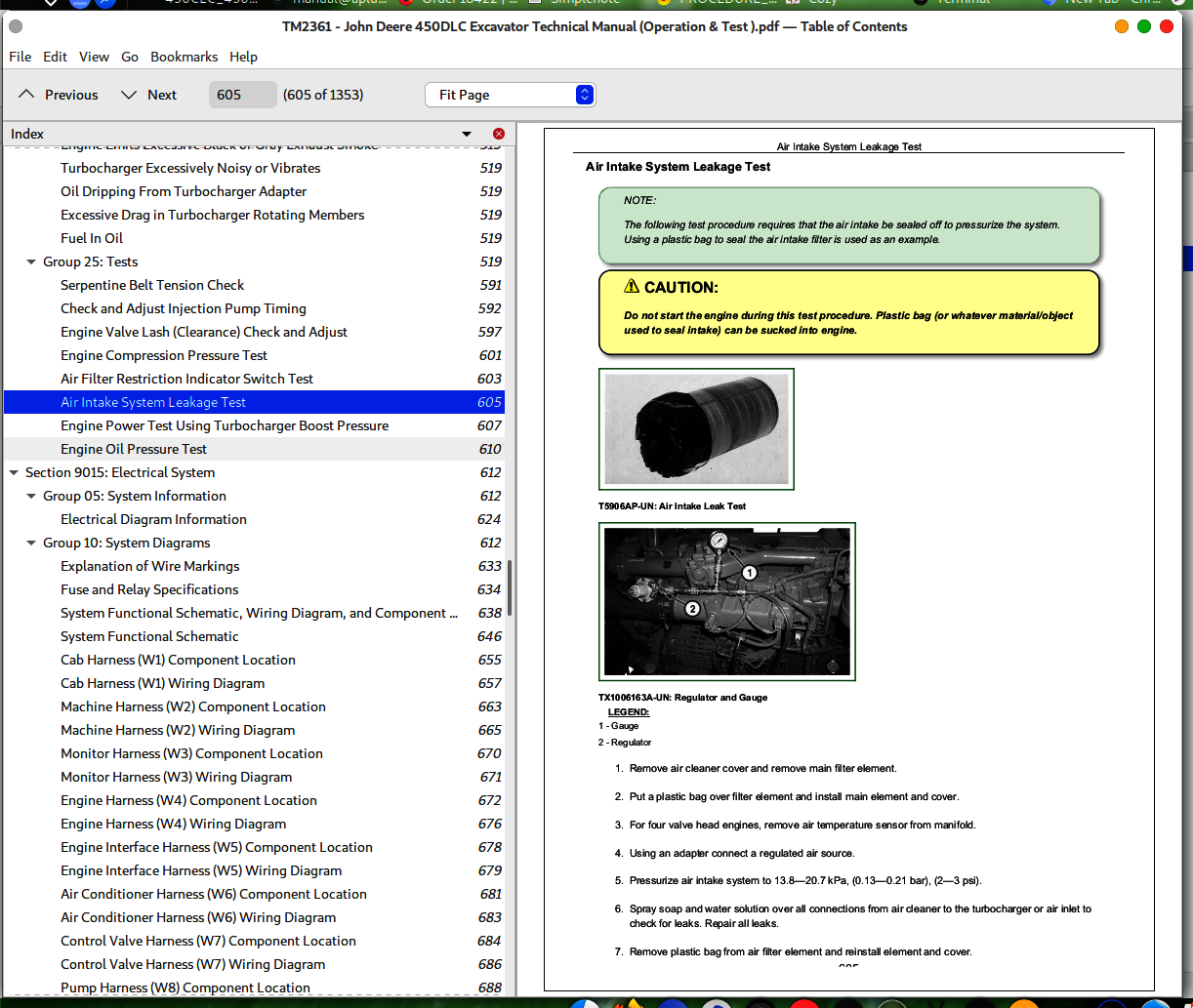
Air Intake System Leakage Test....605
Engine Power Test Using Turbocharger Boost Pressure....607
Engine Oil Pressure Test....610
Section 9015: Electrical System....612
Group 05: System Information....612
Electrical Diagram Information....624
Group 10: System Diagrams....612
Explanation of Wire Markings....633
Fuse and Relay Specifications....634
System Functional Schematic, Wiring Diagram, and Component Location Master Legend....638
System Functional Schematic....646
Cab Harness (W1) Component Location....655
Cab Harness (W1) Wiring Diagram....657
Machine Harness (W2) Component Location....663
Machine Harness (W2) Wiring Diagram....665
Monitor Harness (W3) Component Location....670
Monitor Harness (W3) Wiring Diagram....671
Engine Harness (W4) Component Location....672
Engine Harness (W4) Wiring Diagram....676
Engine Interface Harness (W5) Component Location....678
Engine Interface Harness (W5) Wiring Diagram....679
Air Conditioner Harness (W6) Component Location....681
Air Conditioner Harness (W6) Wiring Diagram....683
Control Valve Harness (W7) Component Location....684
Control Valve Harness (W7) Wiring Diagram....686
Pump Harness (W8) Component Location....688
Pump Harness (W8) Wiring Diagram....690
Auxiliary Fuse Box Harness (W9) Component Location....691
Auxiliary Fuse Box Harness (W9) Wiring Diagram....693
Cab Switch Harness (W10) Component Location....695
Cab Switch Harness (W10) Wiring Diagram....696
Pilot Shutoff Switch Harness (W11) Component Location....697
Pilot Shutoff Switch Harness (W11) Wiring Diagram....698
Heated Air Seat Harness (W12) Component Location....699
Heated Air Seat Harness (W12) Wiring Diagram....701
Seat Heater Switch Harness (W13) Component Location....702
Seat Heater Switch Harness (W13) Wiring Diagram....703
Multi-Function Pilot Control Lever Harness (W14) Component Location....704
Multi-Function Pilot Control Lever Harness (W14) Wiring Diagram....706
Travel Alarm Cancel Switch Harness (W15) Component Location....707
Travel Alarm Cancel Switch Harness (W15) Wiring Diagram....708
Reversing Fan Switch Harness (W16) Component Location....709
Reversing Fan Switch Harness (W16) Wiring Diagram....710
Pilot Shutoff Valve Harness (W17) Component Location....711
Pilot Shutoff Valve Harness (W17) Wiring Diagram....712
Service Advisor Connector Harness (W22) Component Location....713
Service Advisor Connector Harness (W22) Wiring Diagram....715
JDLink™ System Harnesses Component Location—MIG/GTT....717
JDLink™ System Harnesses Component Location—MTG/SAT....719
JDLink™ System Wiring Diagrams—MIG/GTT....721
JDLink™ System Wiring Diagrams—MTG/SAT....726
Group 15: Sub-System Diagnostics....613
Controller Area Network (CAN) Theory of Operation....729
Starting and Charging Circuit Theory of Operation....731
Quick On System (QOS) Preheat Circuit Theory of Operation....734
Monitor Circuit Theory of Operation....736
Engine Control Module (ECM) Circuit Theory of Operation....742
Main Controller (MCF) Circuit Theory of Operation....747
Information Controller (ICF) Theory of Operation....764
Travel Alarm Circuit Theory of Operation....765
Windshield Wiper and Washer Circuit Theory of Operation....767
Pilot Shutoff Circuit Theory of Operation....770
JDLink™ Circuit Theory of Operation—If Equipped....773
Group 16: Monitor Operation....613
Monitor Menu Operation....777
Monitor Service Menu Operation....778
Group 20: References....613
Monitor Data Items....782
Monitor Data Items Using the Monitor Display....784
Reading Diagnostic Trouble Codes With Monitor Display....786
JDLink™ System Identification....788
JDLink™ Connection Procedure....791
Service ADVISOR™ Diagnostic Application....792
Service ADVISOR™ Connection Procedure....793
Reading Diagnostic Trouble Codes With Service ADVISOR™ Diagnostic Application....794
MPDr Application....797
MPDr Connection Procedure....798
Service ADVISOR™ Interactive Tests....800
Information Controller (ICF) Recorded Data....801
Pump Learning Procedure....804
Fuse Test....806
Relay Test....810
Pressure Sensor Test....811
Solenoid Test....813
Proportional Solenoid Test....814
Alternator Test....815
Electrical Component Checks....817
Battery Remove and Install....828
Rear Cover Remove and Install....831
Main Controller (MCF) Remove and Install....833
Engine Control Module (ECM) Remove and Install....834
Information Controller (ICF) Remove and Install....836
Monitor Controller Remove and Install....837
Key Switch Remove and Install....840
Switch Panel Remove and Install....842
Travel Alarm Remove and Install....844
Left Console Switch Remove and Install....845
Disconnect Tab Retainer Connectors....846
Disconnecting Spring Wire Clip Connectors....847
Replace DEUTSCH DEUTSCH is a trademark of the Deutsch Co. Connectors....614
Replace DEUTSCH DEUTSCH is a trademark of Deutsch Co. Rectangular or Triangular Connectors....614
Install DEUTSCH DEUTSCH is a trademark of the Deutsch Co. Contact....615
Replace WEATHER PACK WEATHER PACK is a trademark of Packard Electric. Connector....615
Install WEATHER PACK WEATHER PACK is a trademark of Packard Electric. Contact....615
Replace (Pull Type) Metri-Pack™ Connectors....858
Replace (Push Type) Metri-Pack™ Connectors....860
Replace CINCH CINCH is a trademark of the Cinch Co. Connectors....615
Install CINCH CINCH is a trademark of the Cinch Co. Contact....615
Repair 32 and 48 Way CINCH CINCH is a trademark of the Cinch Co. Connectors....615
Remove Connector Body from Blade Terminals....869
Section 9020: Power Train....870
Group 05: Theory of Operation....870
Track Adjuster and Recoil Spring Operation....872
Travel Gearbox Operation....873
Group 15: Diagnostic Information....870
Diagnose Undercarriage Components Malfunctions....870
Measure Swing Bearing Wear....893
Section 9025: Hydraulic System....897
Group 05: Theory of Operation....897
Hydraulic System Diagram and Operation....903
Fan Drive System Diagram and Operation....905
Pilot System Diagram and Operation....908
Pilot Pump, Pressure Regulating Valve, and Filter Operation....911
Pilot Check Valve Manifold and Accumulator Operation....913
Boom Lowering With Engine Stopped Circuit Operation....915
Pilot Shutoff Solenoid Valve Operation....917
Pilot Control Valve Operation....954
Travel Pilot Control Valve Operation....954
Boom Up Shockless Valve Operation....926
Pilot Signal Manifold Operation....927
Pilot Operation of Control Valve Operation....954
Pump 1 and 2, Fan Drive Pump, and Gearbox Operation....938
Pump 1 and 2 Regulator Operation....941
Fan Drive Pump Regulator Operation....945
Control Valve Operation....954
Control Valve Check Valves Identification and Operation....968
Main Relief and Power Digging Valve Circuit Operation....972
Circuit Relief and Anticavitation Valve Operation....977
Arm Make-Up Check Valve Operation....979
Travel Flow Combiner Valve Circuit Operation....981
Boom Regenerative Valve Circuit Operation....984
Arm Regenerative Valve Circuit Operation....986
Bucket Regenerative Valve Circuit Operation....989
Boom and Arm Reduced Leakage Valves Operation....994
Boom Flow Rate Circuit Operation....998
Arm 2 Flow Rate Circuit Operation....1004
Boom Mode Circuit Operation....1007
Counterweight Removal Circuit Operation....1010
Swing Gearbox Operation....1011
Swing Motor and Park Brake Circuit Operation....1012
Swing Motor Park Brake Release Circuit Operation....1016
Center Joint Operation....1017
Travel Motor and Park Brake Circuit Operation....1018
Travel Motor Speed Circuit Operation....1020
Boom, Arm, and Bucket Cylinder Operation....1022
Counterweight Removal Cylinder Operation....1024
Return Filter Operation....1025
Auxiliary System Operation....1027
Secondary Auxiliary Relief Valve Operation....1028
Selector Valve Operation....1030
Auxiliary High Flow Hydraulics Accumulator Kit....1032
Auxiliary High Flow Line Kit Operation....1034
Two-Way Solenoid Kit Operation....1037
Two-Way Hydraulic Foot Pedal Control Kit....1040
Group 15: Diagnostic Information....898
Diagnose No Hydraulics Malfunctions....898
Diagnose All Hydraulics Slow Malfunctions....898
Diagnose All Hydraulic Functions Too Fast Malfunctions....898
Diagnose Hydraulic Overheating Malfunctions....898
Diagnose Fan Drive Hydraulic System Malfunctions....898
Diagnose Pilot Circuit Malfunctions....898
Diagnose Dig Circuit Malfunctions....898
Diagnose Swing Circuit Malfunctions....898
Diagnose Travel Circuit Malfunctions....898
Diagnose Counterweight Removal System Malfunctions....898
Diagnose Auto Lubrication System Malfunctions....898
Pump 1, Pump 2 and Pilot Pump Line Identification....1158
Control Valve Line Identification....1160
Swing Motor Line Identification....1163
Control Lever Pattern Conversion....1165
Pilot Control Valve-to-Pilot Signal Manifold Component Location—Excavator Pattern....1170
Pilot Control Valve-to-Pilot Signal Manifold Component Location—Backhoe Pattern....1172
Pilot Signal Manifold-to-Control Valve Line Connections....1174
Travel Hydraulic System Component Location....1182
Travel Hydraulic System Line Connection....1178
Fan Drive Hydraulic System Component Location....1182
Fan Drive Hydraulic System Line Connections....1184
Hydraulic System Component Location....1182
Hydraulic System Line Connections....1184
Counterweight Removal Hydraulic System Component Location....1185
Counterweight Removal Hydraulic System Line Connections....1186
Hydraulic System Schematic....1187
Auxiliary Attachment Schematic....1203
Group 25: Tests....899
Hydraulic Test Port Location....1210
JT05800 Digital Thermometer Installation....1211
JT02156A Digital Pressure/Temperature Analyzer Installation....1212
Hydraulic Oil Cleanup Procedure Using Portable Filter Caddy....1213
Hydraulic Oil Warm-Up Procedure....1215
Pilot Pressure Regulating Valve Test and Adjustment....1218
Control Valve Spool Actuating Pilot Pressure Test....1222
Power Dig Solenoid Valve (port SG) Test and Adjustment....1225
Travel Speed Solenoid Valve (port SI) Test and Adjustment....1230
Boom Mode Solenoid Valve (port SC) Test and Adjustment....1235
Boom Flow Rate Solenoid Valve (port SF) Test and Adjustment....1240
Main Relief and Power Digging Valve Test and Adjustment....1245
Circuit Relief Valve Test and Adjustment....1251
Boom Mode Relief Valve Test and Adjustment....1257
Pump Servo Piston Minimum Flow Test and Adjustment....1262
Pump Servo Piston Maximum Flow Test and Adjustment....1266
Pump Flow Rate (Displacement) Test and Adjustment....1270
Swing Motor Crossover Relief Valve Test and Adjustment....1272
Travel Motor Crossover Relief Valve Test and Adjustment....1277
Swing Motor Leakage Test....1281
Travel Motor Leakage Test....1287
Cylinder Drift Test—Arm, Boom, and Bucket....1290
Pump Flow Test....1293
Fan Speed Test....1298
Fan Motor Case Drain Test....1300
Fan Drive Pump Flow Test....1303
Fan Drive System Relief Valve Test and Adjustment....1307
Fan Drive Pump Servo Piston Minimum Flow Test and Adjustment....1311
Fan Drive Pump Servo Piston Maximum Flow Test and Adjustment....1313
Fan Drive Pump Flow Rate Test and Adjustment....1315
Fan Drive Pump Torque Control Test and Adjustment....1317
Section 9031: Heating and Air Conditioning System....1319
Group 05: Theory Of Operation....1319
Air Conditioning System Cycle of Operation....1322
Group 15: Diagnostic Information....1319
Diagnose Air Conditioning System Malfunctions....1327
Diagnose Heating System Malfunctions....1330
Air Conditioner and Heater Diagnostic Trouble Code Check....1332
Heater and Air Conditioner Component Location....1333
Group 25: Tests....1319
Refrigerant Cautions and Proper Handling....1335
Heating and Air Conditioning Operational Checks....1336
R134a Air Conditioning System Test....1340
Air Conditioner Compressor Clutch Test....1341
Refrigerant Leak Test....1342
Refrigerant Hoses and Tubing Inspection....1343
Air Conditioner Compressor Belt Check and Adjustment....1344
Operating Pressure Diagnostic Chart....1345
Section 9050: Reference Material....1347
Group 05: Terminology Cross Reference Chart....1350
Terminology Cross Reference Chart....1350
John Deere 450DLC Excavator Operation & Test Workshop Manual - TM2361


