John Deere 444H, 544H Loader and TC44H, TC54H Tool Carrier Workshop Service Repair Manual - TM1605
Catalog:
Model:
John Deere 444H, 544H Loader and TC44H, TC54H Tool Carrier Workshop Service Repair manual (including maintenance, overhaul, disassembling & assembling, adjustment, tune-up, operation, inspecting…) is divided into different sections. Each section covers a specific component or system with detailed illustrations. A table of contents is placed at the beginning of each section. Pages are easily found by category, and each page is expandable for great detail. The printer-ready PDF documents work like a charm on all kinds of devices.
John Deere 444H, 544H Loaders and TC44H, TC54H Tool Carrier manual contains high quality images, instructions to help you to maintain, and repair. This document is printable, without restrictions, contains searchable text, bookmarks, crosslinks for easy navigation.
TM1605 - John Deere 444H, 544H Loader and TC44H, TC54H Tool Carrier Technical Manual - Repair.pdf
TABLE OF CONTENTS:
Contents.........5
General Information.........7
Safety Information.........9
Handle Fluids Safely—Avoid Fires.........9
Prevent Battery Explosions.........9
Prepare for Emergencies.........9
Prevent Acid Burns.........10
Handle Chemical Products Safely.........10
Avoid High-Pressure Fluids.........11
Park Machine Safely.........11
Support Machine Properly.........11
Wear Protective Clothing.........12
Work in Clean Area.........12
Service Machines Safely.........12
Work In Ventilated Area.........13
Illuminate Work Area Safely.........13
Replace Safety Signs.........13
Use Proper Lifting Equipment.........14
Remove Paint Before Welding or Heating.........14
Avoid Heating Near Pressurized Fluid Lines.........14
Keep ROPS Installed Properly.........15
Service Tires Safely.........15
Avoid Harmful Asbestos Dust.........16
Practice Safe Maintenance.........16
Use Proper Tools.........17
Decommissioning — Proper Recycling and Disposal of Fluids and Components.........17
Live With Safety.........18
General Specifications.........19
444H Specifications.........19
Drain and Refill Capacities—444H.........20
TC44H Specifications.........21
Drain and Refill Capacities—TC44H.........22
544H Specifications.........23
Drain and Refill Capacities—544H.........25
TC54H Specifications.........26
Drain and Refill Capacities—TC54H.........28
Torque Values.........29
Hardware Torque Specifications.........29
ROPS Torque Specifications.........29
Metric Bolt and Screw Torque Values.........30
Additional Metric Cap Screw Torque Values.........31
Unified Inch Bolt and Screw Torque Values.........32
Check Oil Lines And Fittings.........33
Service Recommendations for O-Ring Boss Fittings.........33
Service Recommendations For Flat Face O-Ring Seal Fittings.........35
Service Recommendations for Metric Series Four Bolt Flange Fitting.........36
Service Recommendations For Inch Series Four Bolt Flange Fittings.........37
Fuels and Lubricants.........39
Diesel Fuel.........39
Lubricity of Diesel Fuels.........39
Low Sulfur Diesel Fuel Conditioner.........39
Diesel Fuel Storage.........40
Fuel Tank.........40
Diesel Engine Oil.........41
Transmission, Hydraulic System, Park Brake, and Differential Oil.........42
Grease.........43
Alternative and Synthetic Lubricants.........43
Lubricant Storage.........43
Mixing of Lubricants.........44
Wheels.........45
Powered Wheels and Fasteners.........47
Service Equipment and Tools.........47
Specifications.........47
Remove and Install Wheel.........47
Remove Tire.........48
Install Tire.........49
Axles and Suspension Systems.........51
Removal and Installation.........53
John Deere TeamMateTeamMate is a trademark of Deere & Company.™ III Axles—Use CTM150.........53
Service Equipment and Tools.........53
Specifications.........54
Remove and Install Front Axle and Differential.........55
Remove Rear Axle and Differential.........58
Install Rear Axle and Differential.........62
Disassemble and Assemble Axle Oscillating Supports.........64
Axle Shafts and U-Joints.........67
Specifications.........67
Remove and Install Universal Joint and Drive Shaft.........68
Disassemble, Inspect, and Assemble Universal Joint Drive Shaft.........69
Axle Shaft, Bearings, Reduction Gears.........71
John Deere TeamMateTeamMate is a trademark of Deere & Company.™ III Axles—Use CTM150.........71
Service Equipment and Tools.........71
Specifications.........72
Axle Disconnect Input Shaft, Cross-Sectional View.........73
Remove and Install Axle Disconnect Input Shaft.........74
Disassemble, Inspect, and Assemble Axle Disconnect Input Shaft.........74
Hydraulic System.........85
Specifications.........85
Remove and Install Differential Lock Solenoid Valve.........85
Axle Recirculation System.........86
Axle Recirculation System With Optional Oil Coolers.........87
Axle Oil Coolers—Exploded View.........88
Remove and Install Front Axle Oil Cooler.........89
Disassemble and Assemble Front Axle Oil Cooler.........91
Remove and Install Rear Axle Oil Cooler.........92
Transmission.........93
Removal and Installation.........95
Essential Tools.........95
Service Equipment and Tools.........95
Specifications.........95
Remove and Install Transmission.........96
Gears, Shafts, Bearings and Power Shift Clutch.........99
Essential Tools.........99
Service Equipment and Tools.........100
Other Material.........100
Specifications.........101
Remove Torque Converter And Housing.........102
Install Torque Converter And Housing.........105
Remove Clutches, Input and Output Shafts.........109
Install Clutches, Input and Output Shafts.........116
Disassemble Clutch Pack KV and KR.........127
Assemble Clutch Pack KV and KR.........130
Disassemble Clutch Pack K1, K2, and K3.........138
Assemble Clutch Pack K1, K2, and K3.........141
Disassemble Clutch Pack K4.........149
Assemble Clutch Pack K4.........150
Disassemble Input Shaft.........158
Assemble Input Shaft.........158
Hydraulic System.........163
Specifications.........163
Remove Transmission Pump.........163
Remove and Install Converter Minimum Pressure Regulator Valve.........165
Install Transmission Pump.........166
Remove Transmission Hydraulic Control Valve.........169
Install Transmission Hydraulic Control Valve.........171
Transmission Hydraulic Control Valve Cross Section View.........173
Disassemble Transmission Control Valve.........174
Assemble Transmission Control Valve.........177
Remove, Disassemble and Install Converter Relief Valve.........184
Transmission Internal Oil Pipes and Tubes Remove and Install.........186
Dealer Fabricated Tools.........191
DFT1148 Pre-Load Clutch Pack Compression Ring Tool.........191
DFT1149 Pre-Load Clutch Pack Compression Ring Tool.........192
Engine.........193
Removal and Installation.........195
PowerTechPowerTech is a trademark of Deere & Company.® 4.5 L (4045) and 6.8 L (6068) John Deere Engines—Use CTM104.........195
Service Equipment and Tools.........195
Specifications.........195
Remove and Install Engine.........196
Engine Auxiliary Systems.........203
Cold Weather Starting Aids.........205
Other Material.........205
Specifications.........205
Remove and Install Fluid Starting Aid Assembly.........205
Remove and Install Engine Coolant.........207
Cooling System.........209
Specifications.........209
Remove and Install Fan Belt.........209
Serpentine Belt Routing.........211
Remove and Install Fan and Fan Drive.........212
Remove and Install Radiator and Oil Cooler.........214
Disassemble and Assemble Radiator and Oil Cooler.........216
Speed Controls.........219
Service Equipment and Tools.........219
Specifications.........219
Remove and Install Speed Control Linkage.........220
Adjust Speed Control Linkage.........221
Adjust Slow and Fast Idle.........222
Intake System.........223
Essential Tools.........223
Service Equipment and Tools.........223
Specifications.........223
Remove and Install Air Cleaner.........224
Remove and Install Air Filter Elements.........225
Clean Dusty Primary Element.........226
Clean Oily or Sooty Primary Element.........227
Inspect Element.........227
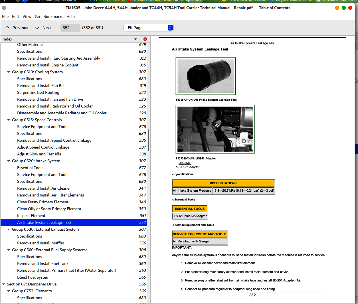
Air Intake System Leakage Test.........228
External Exhaust System.........229
Specifications.........229
Remove and Install Muffler.........230
External Fuel Supply Systems.........233
Specifications.........233
Remove and Install Fuel Tank.........234
Remove and Install Primary Fuel Filter (Water Separator).........236
Bleed Fuel System.........237
Dampener Drive.........239
Elements.........241
Specifications.........241
Remove and Install Dampener.........241
Steering System.........243
Hydraulic System.........245
Service Equipment and Tools.........245
Other Material.........245
Specifications.........245
Remove and Install Steering Valve.........246
Remove and Install Steering Column.........249
Remove and Install Steering Cylinders.........250
Loader Start-Up Procedure (Steering Cylinder).........250
Remove and Install Steering Cylinder Bushings.........251
Disassemble and Assemble Steering Cylinder.........251
Loader Start-Up Procedure (Steering Cylinder—120 Series).........251
Service Brakes.........253
Active Elements.........255
Service Equipment and Tools.........255
Specifications.........255
Inspect External Service Brakes.........255
Remove and Install Brake Assembly.........256
Hydraulic System.........257
Specifications.........257
Remove and Install Brake Valve.........257
Remove and Install Brake Accumulator.........259
Park Brake.........261
Active Elements.........263
Service Equipment and Tools.........263
Other Material.........263
Specifications.........263
Remove and Install Park Brake.........264
Disassemble and Assemble Park Brake.........266
Hydraulic System.........271
Specifications.........271
Remove and Install Park Brake Release Solenoid Valve.........271
Remove and Install Park Brake Pressure Switch.........272
Electrical System.........275
Batteries, Support and Cables.........277
Specifications.........277
Service Batteries Carefully.........277
Check Battery Electrolyte Level and Terminals.........278
Battery Charging Procedure.........279
Using Booster Batteries—24 Volt System.........280
Procedure for Testing Batteries.........281
Remove and Install Batteries.........282
Remove and Install Manual Battery Disconnect Switch.........283
Alternator, Regulator and Charging System Wiring.........285
Bosch Alternator Repair—Use CTM77.........285
Remove and Install Alternator.........285
Remove and Install Regulator.........288
Lighting System.........289
Remove and Install Work Lights.........289
Remove and Install Front Turn Lights.........291
Replace Halogen Bulbs.........291
Remove and Install Stop, Turn and Tail Light.........293
Wiring Harness and Switches.........295
Essential Tools.........295
Other Material.........296
Remove and Install Transmission Control Valve Connector Body.........297
Install Transmission Control Valve Connector Contact.........298
Replace METRI-PACKMetri-Pack is a trademark of Packard Electrical.™ Connectors.........298
Install METRI-PACKMetri-Pack is a trademark of Packard Electric.™ Contact.........299
Replace DEUTSCHDEUTSCH is a trademark of the Deutsch Co.™ Connectors.........301
Install DEUTSCHDEUTSCH is a trademark of the Deutsch Co.™ Contact.........302
Replace WEATHER PACKWEATHER PACK is a trademark of Packard Electric.™ Connector.........303
Install WEATHER PACKWEATHER PACK is a trademark of Packard Electric.™ Contact.........304
Replace Chassis Computer Unit Connector Terminals.........305
Install CINCHCINCH is a trademark of the Cinch Co.™ Contact.........307
Remove Connector Body from Blade Terminals.........308
Remove Blade Terminals From Fuse Block.........308
Remove and Install Pressure Switches.........309
Boom Height Kickout, Return-to-Carry and Return-to-Dig Kickout Adjustments.........309
System Controls.........311
Remove and Install Transmission Controller.........311
Remove and Install Chassis Computer Unit.........313
Remove and Install Monitor Display Unit.........314
Reprogram Monitor Display Unit.........317
Motors and Actuators.........319
John Deere Starting Motor Repair—Use CTM77.........319
Specifications.........319
Remove and Install Starting Motor.........319
Frame or Supporting Structure.........321
Frame Installation.........323
Service Equipment and Tools.........323
Specifications.........323
Welding Major Structure.........324
Separate Engine and Loader Frame.........325
Remove and Install Upper Pivot Bearing and Seals.........330
Remove and Install Lower Pivot Bearing and Seals.........332
Frame Bottom Guards.........335
Specifications.........335
Remove and Install Fuel Tank Guard.........335
Remove and Install Front Axle Guard.........335
Remove and Install Transmission Bottom Guard.........336
Remove and Install Transmission Side Guards.........336
Chassis Weights.........337
Specifications.........337
Remove and Install Counterweights.........337
Operator’s Station.........339
Removal and Installation.........341
Essential Tools.........341
Service Equipment and Tools.........341
Specifications.........341
Remove and Install Cab or Canopy.........342
Operator Enclosure.........347
Other Material.........347
Specifications.........347
Remove and Install Windowpanes.........347
Adjust Cab Door Hold-Open Release.........347
Remove and Install Windshield Washer.........348
Remove and Install Front and Rear Windshield Wiper Motor.........349
Adjust Front Windshield Wiper.........350
Remove and Install Wrist Support.........351
Seat and Seat Belts.........353
Disassemble and Assemble Seat Belt.........353
Disassemble and Assemble Seat.........354
Heating and Air Conditioning.........357
Essential Tools.........357
Service Equipment and Tools.........358
Air Conditioning System Fittings Reference Chart.........359
Other Material.........360
Specifications.........360
Refrigerant Theory of Operation.........361
R134a Refrigerant Cautions.........362
R134a Compressor Oil Charge Check.........362
R134a Compressor Oil Removal.........362
R134a Component Oil Charge.........363
Leak Testing.........363
Refrigerant Hoses and Tubing Inspection.........364
R134a Refrigerant, Recovery, Recycling and Charging Station Installation Procedure.........364
Recover R134a System.........365
Evacuate R134a System.........366
Charge R134a System.........367
Air Conditioner System Cleaning Procedures.........368
Purge Air Conditioner System.........368
Flush Air Conditioner System.........369
Blower/Air Conditioner Harness (W20) Component Location.........370
Connectors for Blower/Air Conditioner Harness (W20).........373
Air Conditioning Module With Heater/Evaporator Coil.........374
Remove and Install Heater/Evaporator Coil.........376
Expansion Valve Remove and Install.........377
Remove and Install Freeze Control Switch.........378
Bench Test Freeze Control Switch.........378
Remove and Install Heater Control Valve.........379
Heater Control Valve Leak Check.........379
Remove and Install Main Blower Assembly.........380
Remove and Install Pressurizer Motor Assembly.........381
Remove and Install Receiver-Dryer and Condenser.........382
Remove and Install High and Low Pressure Switches.........383
Remove and Install Fresh Air Filter.........384
Remove and Install Recirculating Air Filter.........386
Remove and Install Compressor.........387
Disassemble and Assemble Compressor Clutch—R134a.........389
Check Clutch Hub Clearance—R134a.........390
Inspect Compressor Manifolds.........391
Dealer Fabricated Tools.........393
DFRW20 Compressor Holding Fixture.........393
Sheet Metal and Styling.........395
Hood or Engine Enclosure.........397
Specifications.........397
Remove and Install Hood.........397
Remove and Install Engine Side Shields.........398
Miscellaneous Shields.........401
Remove and Install Transmission Shields.........401
Remove and Install Battery Covers.........402
Grille and Grille Housing.........403
Service Equipment and Tools.........403
Specifications.........403
Remove and Install Grille and Grille Housing—544H.........403
Miscellaneous Shields.........405
Remove and Install Front Fenders.........405
Remove and Install Rear Fenders.........406
Safety and Convenience.........407
Mirror.........409
Remove and Install Rear View Mirror.........409
Remove and Install Outside Mirror for Cab or Canopy.........409
Fire Extinguisher.........411
Remove and Install Fire Extinguisher and Bracket.........411
Horn and Warning Devices.........413
Remove and Install Horn.........413
Remove and Install Reverse Warning Alarm.........414
Change Volume Reverse Warning Alarm.........414
Loader.........416
Bucket.........417
Specifications.........417
Ride Control Accumulator Safety.........417
Remove and Install Bucket Tooth Shanks and Tips.........418
Remove and Install Bucket.........419
Remove and Install Welded Bucket Cutting Edges.........420
Remove and Install Bolt-On Cutting Edges and Wear Plates.........420
Repair Cracked Cutting Edge.........421
Frames.........423
Service Equipment and Tools.........423
Other Material.........423
Specifications.........423
Remove and Install Loader Bucket Tilt Linkage.........424
Remove and Install Bucket Linkage Seals and Bushings.........425
Disassemble and Assemble Upper Tool Carrier Tilt Linkage.........426
Disassemble and Assemble Lower Tool Carrier Tilt Linkage.........427
Disassemble and Assemble Tool Carrier.........428
Remove and Install Loader Boom Bushings and Seals.........429
Remove and Install Tool Carrier Boom Bushings and Seals.........430
Hydraulic System.........431
Essential Tools.........431
Service Equipment and Tools.........431
Other Material.........433
Specifications.........434
Remove and Install Loader Hydraulic Pump.........436
Hydraulic Pump (PVG 65) and (PVG 75) Cross Section.........438
Disassemble, Inspect and Assemble Hydraulic Pump.........439
Remove and Install Hydraulic Pump Control Valve.........461
Disassemble and Assemble Hydraulic Pump Control Valve.........462
Remove and Install Loader Control Valve.........463
Disassemble and Assemble Loader Control Valve.........465
Disassemble and Assemble Auxiliary Valve Section and Bucket Section.........466
Disassemble and Assemble Boom Valve Section.........467
Disassemble and Assemble Relief Valve.........467
Disassemble and Assemble Bucket Circuit Relief Valve.........468
Disassemble and Assemble Load Sense Relief Valve.........468
Disassemble and Assemble Boom Circuit Relief Valve.........469
Remove and Install Boom Cylinder.........470
Remove and Install Bucket Cylinder.........472
Cross Section of 444H Boom and Bucket Cylinders—120 Series.........473
Boom Cylinder Piston Wear Ring Configuration.........474
Disassemble 444H Boom and Bucket Cylinders—120 Series.........475
Assemble 444H Boom and Bucket Cylinders—120 Series.........477
Cross Section of TC44H, TC54H and 544H Boom, Bucket and Tilt Cylinders—125 Series.........484
Disassemble and Assemble TC44H, TC54H and 544H Boom, Bucket and Tilt Cylinders—125 Series Cylinders.........485
Remove and Install Boom or Bucket Cylinder Bushings and Seals.........490
Loader Start-Up Procedure (Boom Cylinder).........491
Loader Start-Up Procedure (Bucket Cylinder).........491
Remove and Install Hydraulic Reservoir.........492
Hydraulic Oil Clean-Up Procedure Using Portable Filter Caddy.........493
Pilot Controller Repair (Single Lever Controller).........494
Pilot Controller Repair (Two Lever Controller) (S.N. —585560).........510
Pilot Controller Repair (Two Lever Controller) (S.N. 585561—).........512
Remove and Install Pressure Reducing Valve Manifold.........514
Remove and Install Pressure Reducing Valve.........515
Disassemble and Assemble Pressure Reducing Valve.........516
Remove and Install Boom Down Solenoid Valve.........517
Remove and Install Differential Lock Solenoid Valve.........518
Remove and Install Pilot Enable Solenoid Valve.........519
Ride Control Valve Remove and Install.........520
Ride Control Valve Disassemble and Assemble.........523
Ride Control Accumulator Remove and Install.........526
Ride Control Accumulator Disassemble and Assemble.........526
Remove and Install Pin Disconnect/Axle Disconnect Valve.........529
Disassemble and Assemble Pin Disconnect Valve.........529
Disassemble and Assemble Axle Disconnect Valve.........530
Auxiliary Hydraulic Oil Cooler System—Exploded View.........531
Remove and Install Auxiliary Hydraulic Oil Cooler.........533
Remove and Install Cooling Pump.........535
John Deere 444H, 544H Loader and TC44H, TC54H Tool Carrier Workshop Service Repair Manual - TM1605


