John Deere 319D and 323D Skid Steer Loader (EH Controls) Workshop Diagnosis Test Manual - tm11422
Catalog:
Model:
John Deere 319D and 323D Skid Steer Loader (EH Controls) Workshop Service Repair manual with Electrical Wiring Diagrams (including maintenance, overhaul, disassembling & assembling, adjustment, tune-up, operation, inspecting, diagnosis & troubleshooting…) is divided into different sections. Each section covers a specific component or system with detailed illustrations. A table of contents is placed at the beginning of each section. Pages are easily found by category, and each page is expandable for great detail. The printer-ready PDF documents work like a charm on all kinds of devices.
John Deere 319D and 323D Skid Steer Loader (EH Controls) manual contains high quality images, circuit diagrams, instructions to help you to maintenance, troubleshoot, diagnose, and repair. This document is printable, without restrictions, contains searchable text, bookmarks, crosslinks for easy navigation.
tm11422 - John Deere 319D and 323D Skid Steer Loader (EH Controls) Technical Manual (Operation & Tests).epub
tm11422 - John Deere 319D and 323D Skid Steer Loader (EH Controls) Technical Manual (Operation & Tests).pdf
TABLE OF CONTENTS...1
Section 9000: General Information...17
Group 01: Safety...17
Recognize Safety Information...20
Follow Safety Instructions...21
Operate Only If Qualified...22
Wear Protective Clothing...23
Avoid Unauthorized Machine Modifications...24
Inspect Machine...25
Stay Clear of Moving Parts...26
Avoid High-Pressure Fluids...27
Avoid High-Pressure Oils...28
Work In Ventilated Area...29
Prevent Fires...30
Prevent Battery Explosions...31
Handle Chemical Products Safely...32
Decommissioning — Proper Recycling and Disposal of Fluids and Components...33
Prepare for Emergencies...34
Clean Debris from Machine...35
Use Steps and Handholds Correctly...36
Start Only From Operator's Seat...37
Use and Maintain Seat Belt...38
Prevent Unintended Machine Movement...39
Avoid Work Site Hazards...40
Keep Riders Off Machine...42
Avoid Backover Accidents...43
Avoid Machine Tip Over...44
Operating On Slopes...45
Operating Or Traveling On Public Roads...46
Inspect and Maintain ROPS...47
Add and Operate Attachments Safely...48
Park and Prepare for Service Safely...49
Service Cooling System Safely...50
Remove Paint Before Welding or Heating...51
Make Welding Repairs Safely...52
Drive Metal Pins Safely...53
Handle Cab Door Safely...54
Section 9001: Diagnostic Trouble Codes (DTCs)...55
Group 10: Engine Control Unit (ECU) Diagnostic Trouble Codes...61
Engine Control Unit (ECU) Diagnostic Trouble Codes...61
000029.03 - Foot Throttle Sensor Out of Range High...55
000029.04 - Foot Throttle Sensor Out of Range Low...55
000029.14 - Foot Throttle Sensor (Out of Range High)...55
000091.03 - Hand Throttle Sensor Out of Range High...55
000091.04 - Hand Throttle Sensor Out of Range Low...55
000091.14 - Hand Throttle Sensor (Out of Range High)...55
000100.03 - Engine Oil Pressure High...55
000107.00 - Engine Air Filter Switch Data Above Normal...55
000171.03 - Ambient Air Temperature Out of Range High...55
000171.04 - Ambient Air Temperature Out of Range Low...55
000237.13 - Vehicle Identification Number...55
000647.05 - Fan Coil Output Driver Out of Range Low...55
000647.06 - Fan Coil Output Driver Out of Range High...55
000647.30 - Fan Coil Output Driver Unknown Fault...55
000676.05 - Glow Plug Relay Output Out of Range Low...55
000676.06 - Glow Plug Relay Output Out of Range High...55
001110.31 - Engine Protection Has Shut Down Engine...55
001321.05 - Starter Relay Output Out of Range Low...55
001321.06 - Starter Relay Output Out of Range High...55
001321.16 - Starter Relay Output Moderately High Value...55
001508.00 - Hydraulic Oil Temperature Data Above Normal...55
001508.03 - Hydraulic Oil Temperature Out of Range High...55
001508.04 - Hydraulic Oil Temperature Out of Range Low...55
001713.00 - Hydraulic Filter Restriction Switch Data Above Normal...55
002023.09 - No EMU on CAN Bus Abnormal Data Rate...55
522826.05 - Fan Reversing Coil Output Out of Range Low...55
522826.06 - Fan Reversing Coil Output Out of Range High...55
Group 20: Engagement and Monitor Unit (EMU) Diagnostic Trouble Codes...117
Engagement and Monitor Unit (EMU) Diagnostic Trouble Codes...117
000070.02 - Park Brake Release Input Erratic or Bad Data...55
000070.04 - Park Brake Release Input Out of Range Low...56
000096.03 - Fuel Level Sensor Out of Range High...56
000096.04 - Fuel Level Sensor Out of Range Low...56
000158.00 - System Voltage Data Above Normal...56
000158.01 - System Voltage Data Below Normal...56
000162.04 - 2-Speed Switch Input Out of Range Low...56
000920.05 - Alarm Output Out of Range Low...56
000920.06 - Alarm Output Out of Range High...56
001196.11 - Anti Theft Unknown Fault...56
001504.04 - Seat Switch Input Out of Range Low...56
001550.05 - AC Compressor Clutch Output Out of Range Low...56
001550.06 - AC Compressor Clutch Output Out of Range High...56
002000.09 - No ECU Data on CAN Bus Abnormal Data Range...56
002228.09 - No HCU Data on CAN Bus Abnormal Data Range...56
003413.04 - Door Switch Input Out of Range Low...56
003597.03 - 5 Volt Sensor Supply 1 Out of Range High...56
003597.04 - 5 Volt Sensor Supply 1 Out of Range Low...56
520850.04 - Over Ride Switch Input Out of Range Low...56
521050.04 - Aux Flow On-Off Switch Input Out of Range Low...56
522379.05 - Park Brake Release Output Out of Range Low...56
522379.06 - Park Brake Release Output Out of Range High...56
522398.02 - Park Brake Run Switch Input Erratic or Bad Data...56
522398.04 - Park Brake Run Switch Input Out of Range Low...56
522820.05 - High Flow Driver Out of Range Low...56
522820.06 - High Flow Driver Out of Range High...56
522826.04 - VSF Purge Switch Input Out of Range Low...56
522827.04 - VSF Auto Switch Input Out of Range Low...56
522828.04 - Creep Mode Switch Input Out of Range Low...56
522859.04 - Lap Bar Switch Input Out of Range Low...56
523217.06 - Hydraulic Valve Power 3 Out of Range High...56
523218.06 - Propel Valve Power 2 to HCU Out of Range High...56
523219.06 - Hydraulic Valve Power 1 Out of Range High...56
523693.03 - Aux Hyd Channel 1 Input Out of Range High...56
523693.04 - Aux Hyd Channel 1 Input Out of Range Low...57
523694.03 - Aux Hyd Channel 2 Input Out of Range High...57
523694.04 - Aux Hyd Channel 2 Input Out of Range Low...57
523694.12 - Aux Hyd Channel 2 Input Device Fault...57
523822.04 - High Flow Switch Input Out of Range Low...57
523917.05 - Two Speed Output Out of Range Low...57
523917.06 - Two Speed Output Out of Range High...57
523935.05 - Aux Hyd Extend Output Out of Range Low...57
523935.06 - Aux Hyd Extend Output Out of Range High...57
523941.05 - Aux Hyd Retract Output Out of Range Low...57
523941.06 - Aux Hyd Retract Output Out of Range High...57
524225.04 - Remote Start Input Out of Range Low...57
524264.11 - Checksum Error Unknown Fault...57
Group 30: Hydraulic Control Unit (HCU) Diagnostic Trouble Codes...240
Hydraulic Control Unit (HCU) Diagnostic Trouble Codes...240
000168.03 - Unswitched Power Input Out of Range High...57
000168.04 - Unswitched Power Input Out of Range Low...57
001594.00 - Left Speed Sensor Input Data Above Normal...57
001594.01 - Left Speed Sensor Input Data Below Normal...57
001594.02 - Left Speed Sensor Input Erratic or Bad Data...57
001594.14 - Left Speed Sensor Input...57
001595.00 - Right Speed Sensor Input Data Above Normal...57
001595.01 - Right Speed Sensor Input Data Below Normal...57
001595.02 - Right Speed Sensor Input Erratic or Bad Data...57
001595.14 - Right Speed Sensor Input...57
002201.09 - Right Joystick CAN Data Abnormal Data Rate...57
002213.09 - Left Joystick CAN Data Abnormal Data Rate...57
002660.07 - Right Joystick X-axis Mechanical Fault...57
002661.07 - Right Joystick Y-axis Mechanical Fault...57
002697.07 - Left Joystick X-axis Mechanical Fault...57
002698.07 - Left Joystick Y-axis Mechanical Fault...57
003597.03 - 5 Volt Sensor Supply 1 Out of Range High...57
003597.04 - 5 Volt Sensor Supply 1 Out of Range Low...57
520194.13 - Machine Model ID Wrong or Missing Calibrate Error...58
520194.14 - Machine Model ID Wrong or Missing...58
520652.05 - Bucket Curl Solenoid Current Out of Range Low...58
520652.06 - Bucket Curl Solenoid Current Out of Range High...58
520652.16 - Bucket Curl Solenoid Current Moderately High Value...58
520653.05 - Bucket Dump Solenoid Current Out of Range Low...58
520653.06 - Bucket Dump Solenoid Current Out of Range High...58
520653.16 - Bucket Dump Solenoid Current Moderately High Value...58
520849.03 - Float Switch Input Out of Range High...58
520849.04 - Float Switch Input Out of Range Low...58
522447.05 - Right Pump Fwd Sol Current Out of Range Low...58
522447.06 - Right Pump Fwd Sol Current Out of Range High...58
522447.16 - Right Pump Fwd Sol Current Moderately High Value...58
522448.05 - Right Pump Rev Sol Current Out of Range Low...58
522448.06 - Right Pump Rev Sol Current Out of Range High...58
522448.16 - Right Pump Rev Sol Current Moderately High Value...58
522449.05 - Left Pump Rev Sol Current Out of Range Low...58
522449.06 - Left Pump Rev Sol Current Out of Range High...58
522449.16 - Left Pump Rev Sol Current Moderately High Value...58
522450.05 - Left Pump Fwd Sol Current Out of Range Low...58
522450.06 - Left Pump Fwd Sol Current Out of Range High...58
522450.16 - Left Pump Fwd Sol Current Moderately High Value...58
523217.03 - Hydraulic Valve Power 3 to HCU Out of Range High...58
523217.04 - Hydraulic Valve Power 3 to HCU Out of Range Low...58
523218.03 - Propel Valve Power 2 to HCU Out of Range High...58
523218.04 - Propel Valve Power 2 to HCU Out of Range Low...58
523219.03 - Hydraulic Valve Power 1 to HCU Out of Range High...58
523219.04 - Hydraulic Valve Power 1 to HCU Out of Range Low...58
523411.05 - Boom Down Solenoid Current Out of Range Low...58
523411.06 - Boom Down Solenoid Current Out of Range High...58
523411.16 - Boom Down Solenoid Current Moderately High Value...58
523414.05 - Boom Up Solenoid Current Out of Range Low...58
523414.06 - Boom Up Solenoid Current Out of Range High...58
523414.16 - Boom Up Solenoid Current Moderately High Value...59
523426.05 - Hyd Port Lock Solenoid Current Out of Range Low...59
523426.06 - Hyd Port Lock Solenoid Current Out of Range High...59
524264.11 - Checksum Error Unknown Fault...59
Group 40: Left Joystick Controller (JSL)...59
Left Joystick Controller (JSL) Diagnostic Trouble Codes...353
002697.03 - Left Joystick X-axis Out of Range High...59
002697.04 - Left Joystick X-axis Out of Range Low...59
002697.13 - Left Joystick X-axis Calibrate Error...59
002697.14 - Left Joystick X-axis Error...59
002698.03 - Left Joystick Y-axis Out of Range High...59
002698.04 - Left Joystick Y-axis Out of Range Low...59
002698.13 - Left Joystick Y-axis Calibrate Error...59
002698.14 - Left Joystick Y-axis Error...59
Group 50: Right Joystick Controller (JSR)...59
Right Joystick Controller (JSR) Diagnostic Trouble Codes...363
002660.03 - Right Joystick X-axis Out of Range High...59
002660.04 - Right Joystick X-axis Out of Range Low...59
002660.13 - Right Joystick X-axis Calibrate Error...59
002660.14 - Right Joystick X-axis See Manual...59
002661.03 - Right Joystick Y-axis Out of Range High...59
002661.04 - Right Joystick Y-axis Out of Range Low...59
002661.13 - Right Joystick Y-axis Calibrate Error...59
002661.14 - Right Joystick Y-axis See Manual...59
Section 9005: Operational Checkout Procedure...372
Group 10: Operational Checkout Procedure...372
Operational Checkout...394
Section 9010: Engine...415
Group 05: Theory of Operation...415
John Deere Engine...430
Cold Start Operation...418
Group 15: Diagnostic Information...415
John Deere Engine...430
Engine Cooling System Component Location...422
Engine Fuel System Component Location...423
Engine Intake and Exhaust Component Location...424
Engine Hard to Start or Does Not Start When Cold...415
Group 25: Tests...415
John Deere Engine...430
Engine Power Test Using Turbocharger Boost Pressure...431
Section 9015: Electrical System...436
Group 05: System Information...436
Electrical Diagram Information...442
Electrical Schematic Symbols...445
Group 10: System Diagrams...436
Fuse and Relay Specifications...452
System Functional Schematic, Wiring Diagram and Component Location Master Legend...456
System Functional Schematic...462
Engine Harness (W1) Component Location...469
Engine Harness (W1) Wiring Diagram...470
Cab Harness (W2) Component Location...472
Cab Harness (W2) Wiring Diagram...475
Main Harness (W3) Component Location...478
Main Harness (W3) Wiring Diagram...482
Dual Flasher Harness (W5) Component Location...492
Dual Flasher Harness (W5) Wiring Diagram...495
Rear Light Harness (W7) Component Location...498
Rear Light Harness (W7) Wiring Diagram...499
Radio Harness (W8) Component Location...500
Radio Harness (W8) Wiring Diagram...501
Fan Speed Solenoid Harness (W9) Component Location...502
Fan Speed Solenoid Harness (W9) Wiring Diagram...503
Hydraulic Valve Harness (W10) Component Location...504
Hydraulic Valve Harness (W10) Wiring Diagram...505
Attachment Control Frame Harness (W11) Component Location...506
Attachment Control Frame Harness (W11) Wiring Diagram...507
Attachment Control Boom Harness (W12) Component Location...509
Attachment Control Boom Harness (W12) Wiring Diagram...510
Quik-Tatch™ Frame Harness (W13) Component Location...511
Quik-Tatch™ Frame Harness (W13) Wiring Diagram...513
Quik-Tatch™ Boom Harness (W14) Component Location...515
Quik-Tatch™ Boom Harness (W14) Wiring Diagram...516
Quik-Tatch™ Actuator Harness (W15) Component Location...517
Quik-Tatch™ Actuator Harness (W15) Wiring Diagram...518
Heater and Air Conditioner Harness (W16) Component Location...519
Heater and Air Conditioner Harness (W16) Wiring Diagram...520
Fan Bypass Solenoid Harness (W17) Component Location...521
Fan Bypass Solenoid Harness (W17) Wiring Diagram...522
Group 15: Sub-System Diagnostics...437
Starting Circuit Theory of Operation...527
Controller Area Network (CAN) Theory of Operation...531
Engine Control Unit (ECU) Circuit Theory of Operation...533
Engagement and Monitor Unit (EMU) Circuit Theory of Operation...541
Electrohydraulic (EH) Controls Circuit Theory of Operation...549
Back-Up Alarm Circuit Theory of Operation...554
Quik-Tatch Circuit Theory of Operation...556
Group 16: Monitor Operation...437
Engagement and Monitor Unit Operation...562
Engagement and Monitor Unit Data Items...566
Engagement and Monitor Unit Display Messages...570
Engagement and Monitor Unit Service Menu Operation...573
Engagement and Monitor Unit Initial Configuration...575
Anti-Theft Security System Operation—If Equipped...577
Anti-Theft Security System Configuration—If Equipped...579
Anti-Theft Security System Enable—If Equipped...583
Group 20: References...437
Service ADVISOR™ Connection Procedure...587
Reading Diagnostic Trouble Codes (DTCs)...589
Electrical Component Checks...593
Electrical Component Specifications...607
Solenoid Test...610
Alternator Test...634
Controller Area Network (CAN) Circuit Test...636
Boom and Bucket Calibration...645
Auxiliary Hydraulics Calibration...647
Manual Tracking Adjustment Procedure...649
Hydrostatic System Calibration...650
Engine Control Unit (ECU) Remove and Install...654
Hydraulic Control Unit (HCU) Remove and Install...656
Engagement and Monitor Unit (EMU) Remove and Install...658
Control Panel Remove and Install...661
Left Joystick Controller (JSL) Remove and Install...662
Right Joystick Controller (JSR) Remove and Install...667
Joystick Disassemble and Assemble...672
Backup Alarm Remove and Install...675
Battery Remove and Install...676
Motor Speed Sensor Remove and Install...677
Replace (Pull Type) Metri-Pack™ Connectors...689
Replace (Push Type) Metri-Pack™ Connectors...691
Replace Metri-Pack™ Connectors...692
Replace WEATHER PACK WEATHER PACK is a trademark of Packard Electric. Connector...438
Install WEATHER PACK WEATHER PACK is a trademark of Packard Electric. Contact...438
Replace DEUTSCH DEUTSCH is a trademark of Deutsch Co. Rectangular or Triangular Connectors...438
Replace DEUTSCH DEUTSCH is a trademark of the Deutsch Co. Circular Connectors...438
Replace DEUTSCH DEUTSCH is a trademark of the Deutsch Co. Connectors...438
Install DEUTSCH DEUTSCH is a trademark of the Deutsch Co. Contact...438
Replace CINCH™ Connectors...706
Install CINCH™ Contact...708
Repair 32 and 48 Way CINCH™ Connectors...710
Remove Connector Body from Blade Terminals...714
Section 9020: Power Train...715
Group 05: Theory of Operation...715
Power Train System Operation...717
Hydrostatic Motor Gearbox Operation (S.N. —192141)...718
Hydrostatic Motor Gearbox Operation (S.N. 192142— )...719
Track Adjuster and Recoil Spring Operation...721
Group 15: Diagnostic Information...715
Power Train Component Location...724
Loose Track...715
Tight Track...715
Frequent Track Tension Adjustment Required...715
Excessive Oil Leakage From Idlers And Rollers...715
Section 9025: Hydraulic System...740
Group 05: Theory of Operation...740
Hydraulic System Operation...743
Hydraulic Oil Filter Manifold Operation...744
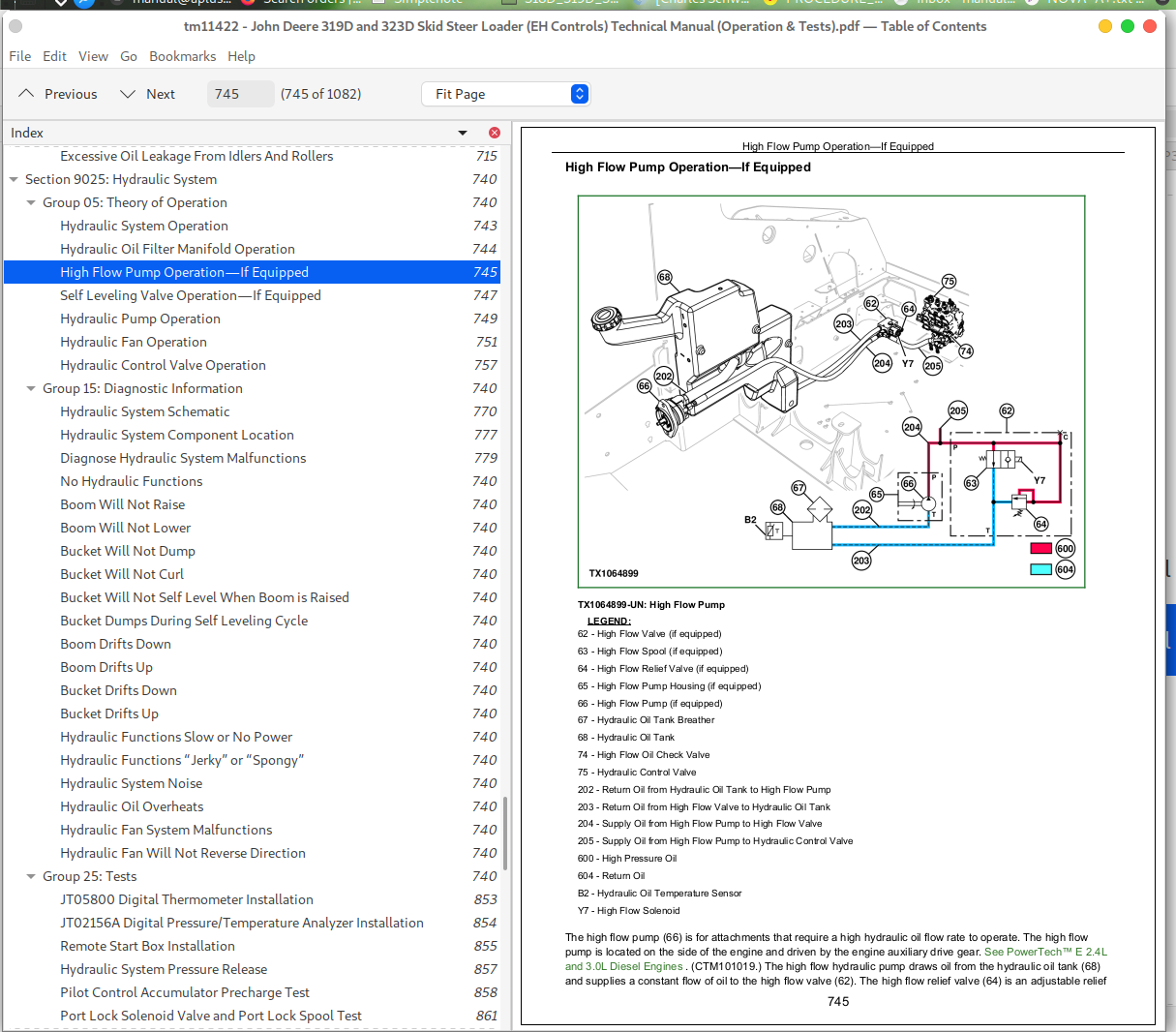
High Flow Pump Operation—If Equipped...745
Self Leveling Valve Operation—If Equipped...747
Hydraulic Pump Operation...749
Hydraulic Fan Operation...751
Hydraulic Control Valve Operation...757
Group 15: Diagnostic Information...740
Hydraulic System Schematic...770
Hydraulic System Component Location...777
Diagnose Hydraulic System Malfunctions...779
No Hydraulic Functions...740
Boom Will Not Raise...740
Boom Will Not Lower...740
Bucket Will Not Dump...740
Bucket Will Not Curl...740
Bucket Will Not Self Level When Boom is Raised...740
Bucket Dumps During Self Leveling Cycle...740
Boom Drifts Down...740
Boom Drifts Up...740
Bucket Drifts Down...740
Bucket Drifts Up...740
Hydraulic Functions Slow or No Power...740
Hydraulic Functions “Jerky” or “Spongy”...740
Hydraulic System Noise...740
Hydraulic Oil Overheats...740
Hydraulic Fan System Malfunctions...740
Hydraulic Fan Will Not Reverse Direction...740
Group 25: Tests...740
JT05800 Digital Thermometer Installation...853
JT02156A Digital Pressure/Temperature Analyzer Installation...854
Remote Start Box Installation...855
Hydraulic System Pressure Release...857
Pilot Control Accumulator Precharge Test...858
Port Lock Solenoid Valve and Port Lock Spool Test...861
Boom Lowering Valve Test (S.N. —194401)...862
Boom Release Cable Adjustment (S.N. —194401)...864
Hydraulic System Relief Valve Test...866
Charge Pressure Relief Valve Test...870
High Flow Relief Valve Test...873
Circuit Relief Valve Test...876
Function Drift Test...886
Hydraulic Cylinder Leakage Test...893
Hydraulic Pump Flow Test...895
Charge Pump Flow Test...900
Hydraulic Fan Motor Speed Test...903
Hydraulic Fan Motor Case Drain Test...908
Fan Bypass Valve Test...911
Hydraulic Oil Cooler Bypass Valve Test—If Equipped...916
Section 9026: Hydrostatic System...918
Group 05: Theory of Operation...918
Hydrostatic System Operation...921
Hydrostatic Pump Operation...922
Charge Pump Operation...928
Hydrostatic Motor Operation—Single Speed (S.N. —192141)...930
Hydrostatic Motor Operation—Two Speed (S.N. —192141)...933
Hydrostatic Motor Operation (S.N. 192142— )...938
Hydrostatic Control Valve Operation...943
Park Brake System Operation...945
Steering Control Operation...947
Group 15: Diagnostic Information...918
Hydrostatic System Schematic...957
Hydrostatic System Component Location...964
Machine Does Not Move In Either Direction...918
Hydrostatic Pump Or Hydrostatic Motor Noise...918
Slow Response To Changes In Speed...918
Low Power...918
Wheels or Tracks Powered On One Side, Not The Other...918
Machine Will Not Shift Into Or Out Of High Speed...918
Mistracking...918
Park Brake Does Not Hold (Single Speed)...918
Park Brakes Do Not Release (Single Speed)...918
Grinding Noise While Operating Machine (Single Speed)...918
Park Brake Does Not Hold (Two Speed)...918
Park Brakes Do Not Release (Two Speed)...918
Grinding Noise While Operating Machine (Two Speed)...918
Group 25: Tests...918
Engine Speed Control for Testing...999
Hydrostatic Pump System Pressure Relief Test...1001
Hydrostatic Pump Flow Test...1005
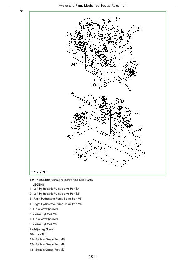
Hydrostatic Pump Mechanical Neutral Adjustment...1009
Hydrostatic Pump Control Neutral Adjustment...1015
Track Speed Test...1018
Park Brake Release Pressure Test...1021
Section 9031: Heating and Air Conditioning...1024
Group 05: Theory of Operation...1024
Air Conditioning System Cycle of Operation...1027
Group 15: Diagnostic Information...1024
Air Conditioning and Heater System Component Location...1031
Air Conditioning System Does Not Operate...1024
Air Conditioning Does Not Cool Interior of Cab...1024
Air Conditioner Runs Constantly, Too Cool...1024
Heater System Does Not Operate...1024
Heater Does Not Warm Interior of Cab...1024
Interior Windows Continue to Fog...1024
Group 25: Tests...1024
Refrigerant Cautions and Proper Handling...1055
Air Conditioner and Heater Operational Checks...1056
Refrigerant Leak Testing...1060
Air Conditioner Compressor Clutch Test...1061
Air Conditioning High-Low Pressure Switch Test...1062
Air Conditioner Freeze Control Switch Test...1065
R134a Refrigerant Cautions...1067
R134a Oil Charge Capacity...1068
R134a Refrigerant Charge Capacity...1069
Operating Pressure Diagnostic Chart...1070
Section 9900: Dealer Fabricated Tools...1075
Group 99: Dealer Fabricated Tools...1075
DFT1318 Motor Speed Sensor Test Harness...1078
DFT1325 Solenoid Power Harness...1080
John Deere 319D and 323D Skid Steer Loader (EH Controls) Workshop Diagnosis Test Manual - tm11422


