John Deere 410J Backhoe Loader (S.N. —161616) Workshop Service Repair Manual - TM10147
Catalog:
Model:
John Deere 410J Backhoe Loader (S.N. —161616) Workshop Service Repair manual (including maintenance, overhaul, disassembling & assembling, adjustment, tune-up, inspecting...) is divided into different sections. Each section covers a specific component or system with detailed illustrations. A table of contents is placed at the beginning of each section. Pages are easily found by category, and each page is expandable for great detail. The printer-ready PDF documents work like a charm on all kinds of devices.
This manual contains high quality images, instructions to help you to maintenance, service and repair. This document is printable, without restrictions, contains searchable text, bookmarks, crosslinks for easy navigation.
TM10147 - John Deere 410J Backhoe Loader (S.N. —161616) Technical Manul (Repair).pdf
TM10147 - John Deere 410J Backhoe Loader (S.N. —161616) Technical Manul (Repair).epub
TABLE OF CONTENTS / FILE LIST:
TABLE OF CONTENTS.....1
Section 00: General Information.....14
Group 0001: Safety Information.....14
Safety and Operator Convenience Features.....17
Recognize Safety Information.....18
Follow Safety Instructions.....19
Operate Only If Qualified.....20
Wear Protective Equipment.....21
Avoid Unauthorized Machine Modifications.....22
Inspect Machine.....23
Stay Clear of Moving Parts.....24
Avoid High-Pressure Fluids.....25
Avoid High-Pressure Oil.....26
Beware of Exhaust Fumes.....27
Prevent Fires.....28
Prevent Battery Explosions.....29
Handle Chemical Products Safely.....30
Dispose of Waste Properly.....31
Prepare for Emergencies.....32
Use Steps and Handholds Correctly.....33
Start Only From Operator's Seat.....34
Use and Maintain Seat Belt.....35
Prevent Unintended Machine Movement.....36
Prevent Unintended Machine Movement—If Equipped With Pilot Controls.....37
Avoid Work Site Hazards.....38
Keep Riders Off Machine.....40
Avoid Backover Accidents.....41
Avoid Machine Tipover.....42
Add and Operate Attachments Safely.....43
Use Special Care When Operating.....44
Operating or Traveling On Public Roads.....45
Inspect and Maintain ROPS.....46
Park and Prepare for Service Safely.....47
Service Cooling System Safely.....48
Remove Paint Before Welding or Heating.....49
Make Welding Repairs Safely.....50
Drive Metal Pins Safely.....51
Safety Signs.....52
Safety Signs—Backhoe Coupler (If Equipped).....54
Group 0003: Torque Values.....15
Metric Bolt and Cap Screw Torque Values.....57
Additional Metric Cap Screw Torque Values.....59
Unified Inch Bolt and Cap Screw Torque Values.....61
Service Recommendations for 37° Flare and 30° Cone Seat Connectors.....63
Service Recommendations for O-Ring Boss Fittings.....65
O-Ring Boss Fittings In Aluminum Housing Service Recommendations—Excavators.....67
Service Recommendations for Flared Connections—Straight or Tapered Threads.....70
Service Recommendations For Flat Face O-Ring Seal Fittings.....72
O-Ring Face Seal Fittings With SAE Inch Hex Nut And Stud End For High Pressure Service Recommendations.....74
O-Ring Face Seal Fittings With Metric Hex Nut And Stud End For Standard Pressure Service Recommendations.....76
O-Ring Face Seal Fittings With Metric Hex Nut And Stud End For High Pressure Service Recommendations.....79
Service Recommendations for Metric Series Four Bolt Flange Fitting.....82
Service Recommendations For Inch Series Four Bolt Flange Fittings.....84
Inch Series Four Bolt Flange Fitting For High Pressure Service Recommendations.....86
Service Recommendations For Non-Restricted Banjo (Adjustable) Fittings.....88
Service Recommendations For O-Ring Boss Fittings With Shoulder.....91
Metric 24° O-Ring Seal DIN 20078 Service Recommendations.....94
Section 01: Wheels.....98
Group 0110: Powered or Non-Powered Wheels and Fastenings.....98
Rear Wheel Assembly Remove and Install.....101
Front Wheel Assembly Remove and Install.....103
Tire Remove and Install.....105
Section 02: Axles and Suspension Systems.....108
Group 0225: Input Drive Shafts and U-Joints.....108
Universal Joint and Drive Shaft Remove and Install.....114
Group 0230: Non-Powered Wheel Axles.....108
Hub Assembly Remove and Install.....121
Spindle Assembly Remove and Install.....123
Tie Rod Remove and Install.....127
Non-Powered Front Axle Remove and Install.....129
Group 0240: Powered Wheel Axle (MFWD).....108
Mechanical Front Wheel Drive (MFWD) Axle Remove and Install.....135
Mechanical Front Wheel Drive (MFWD) Axle Disassembly.....138
Mechanical Front Wheel Drive (MFWD) Axle Assemble.....156
Limited Slip Differential Disassemble and Assemble.....188
Group 0250: Axle Shaft, Bearings, and Reduction Gears.....108
Service Brakes Inspection.....200
Rear Axle Remove and Install.....202
Rear Axle Disassemble.....206
Park Brake Disassemble and Assemble.....223
Rear Axle Assemble.....241
Gear Tooth Contact Pattern Check.....265
Section 03: Transmission.....266
Group 0300: Removal and Installation.....266
Transmission Remove.....276
Transmission Install.....285
Group 0315: Controls Linkage.....266
Transmission Control Lever (TCL) Remove and Install.....294
Group 0350: Gears, Shafts, and Power Shift Clutches.....266
Remove Outer Components to Disassemble Transmission.....301
Torque Converter Side of Transmission Case Disassemble 2WD (S.N. —151467), 4WD (S.N. —149665).....306
Torque Converter Side of Transmission Case Disassemble 2WD (S.N. 151468—), 4WD (S.N. 149666—).....310
Clutch Packs Remove.....314
High Range Forward, Low Range Forward, and Reverse Clutch Packs Disassemble and Assemble.....320
First Speed and Third Speed Clutch Disassemble and Assemble.....340
Second Speed Clutch Disassemble and Assemble.....358
Mechanical Front Wheel Drive (MFWD) Clutch Disassemble and Assemble.....376
Pump Drive Shaft Install.....389
Clutch Packs Install.....391
Torque Converter Side of Transmission Case Assemble 2WD (S.N. —151467), 4WD (S.N. —149665).....397
Torque Converter Side of Transmission Case Assemble 2WD (S.N. 151468—), 4WD (S.N. 149666—).....404
Install Outer Components to Assemble Transmission.....412
Group 0360: Hydraulic System.....266
Transmission Charge Pump Remove and Install.....421
Transmission Charge Pump Disassemble and Assemble.....425
Section 04: Engine.....427
Group 0400: Removal and Installation.....427
POWERTECH 4.5L (4045) and 6.8L (6068) John Deere Engines.....429
Engine Remove.....430
Engine Install.....438
Section 05: Engine Auxiliary Systems.....445
Group 0505: Cold Weather Starting Aid.....445
Coolant Heater Remove and Install.....449
Starting Aid Nozzle Remove and Install.....452
Starting Aid Solenoid Remove and Install.....454
Group 0510: Cooling System.....445
Fan Remove and Install.....458
Fan Belt Remove and Install.....460
Radiator Remove and Install.....462
Group 0515: Speed Controls.....445
Engine Speed Control Pedal Remove and Install.....471
Group 0520: Intake System.....445
Air Cleaner Remove and Install.....475
Group 0530: Exhaust System.....445
Muffler with Turbocharger Remove and Install.....479
Group 0560: External Fuel Supply System.....445
Fuel Tank Remove and Install.....484
Section 06: Torque Converter.....487
Group 0651: Turbine, Gears and Shaft.....487
Torque Converter Remove and Install.....489
Torque Converter Disassemble and Assemble.....490
Section 09: Steering System.....491
Group 0960: Hydraulic System.....491
Steering Column Remove and Install.....497
Standard Steering Wheel and Column Disassemble and Assemble.....502
Tilt Steering Wheel and Column Disassemble and Assemble.....504
Steering Valve Remove and Install.....506
Steering Valve Disassemble and Assemble.....514
Non-Powered Front Axle Steering Cylinder Repair.....520
Mechanical Front Wheel Drive (MFWD) Axle Steering Cylinder Disassemble and Assemble.....525
Section 10: Service Brakes.....531
Group 1011: Active Elements.....531
Service Brake External Inspection.....533
Brake Disk and Pressure Plate Remove and Install.....534
Group 1060: Hydraulic System.....531
Brake Valve Remove and Install.....542
Brake Valve Disassemble and Assemble.....549
Brake Valve Lines Disassemble and Assemble.....556
Brake Pedals Remove and Install.....558
Brake Pedal Adjustment.....560
Brake Bleeding Procedure.....562
Section 11: Park Brake.....566
Group 1111: Active Elements.....566
Park Brake Remove and Install.....568
Section 17: Frame or Supporting Structure.....569
Group 1740: Frame Installation.....569
Welding Repair of Major Structures.....571
RIVNUT RIVNUT is a registered trademark of The BF Goodrich Co. (KREMNUT) Fasteners Remove and Install.....569
Main Frame Bushings Remove and Install.....575
Group 1749: Chassis Weights.....569
Counterweight Remove and Install.....578
Section 18: Operator’s Station.....580
Group 1800: Removal and Installation.....580
Cab/ROPS Remove and Install.....598
Group 1810: Operator Enclosure.....580
Front Window Wiper and Wiper Motor Remove and Install.....617
Rear Window Wiper and Wiper Motor Remove and Install.....620
Front Cab Windowpane Remove and Install.....623
Fixed Windowpanes Remove and Install.....625
Cab Door and Side Window Disassemble and Assemble.....626
Cab Door Hinges and Latch Adjustment.....629
Upper Cab Door and Side Windowpanes Adjustment.....631
Upper Cab Door and Side Window Latch Adjustment.....633
Rear Window and Frame Assembly Remove and Install.....634
Rear Windows Remove and Install.....637
Headliner Remove and Install.....640
Cab Roof Remove and Install.....641
Group 1821: Seat and Seat Belt.....580
Seat Assembly Remove and Install.....645
Seat and Arm Rest Disassemble and Assemble.....647
Seat Belt Disassemble and Assemble.....649
Seat Slide, Lumbar Support, and Adjuster Control Levers Disassemble and Assemble.....651
Seat Swivel and Swivel Latch Disassemble and Assemble.....653
Seat Suspension and Shock Absorber Disassemble and Assemble.....655
Air Suspension Seat Disassemble and Assemble—If Equipped.....657
Group 1830: Heating and Air Conditioning.....580
Proper Refrigerant Handling.....668
R134a Refrigerant—Cautions.....669
Refrigerant Hoses and Tubing Inspection.....670
Air Conditioning Compressor Remove and Install.....671
R134a Compressor Oil Removal Procedure.....673
Air Conditioning Compressor Clutch Disassemble and Assemble.....674
Clutch Hub Clearance Check.....676
Air Conditioning Compressor Manifold Inspection.....677
Air Conditioning Compressor Disassemble and Assemble.....678
Heater Core Remove and Install.....682
Evaporator Remove and Install.....687
Air Conditioning Freeze Switch Remove and Install.....692
Heater/Blower Assembly with Air Conditioning and Pressurizer System Disassemble and Assemble.....696
Air Ducts Disassemble and Assemble.....700
Condenser Disassemble and Assemble.....702
Receiver Dryer Remove and Install.....705
Expansion Valve—Remove and Install.....708
R134a Component Oil Charge Procedure.....709
R134a Refrigerant Recover, Recycle, and Charge Station Installation Procedure.....711
R134a System Recover Procedure.....713
R134a System Evacuate Procedure.....715
R134a System Charge Procedure.....718
R134a System Cleaning Procedure.....720
R134a System Leak Testing.....721
R134a System Flush Procedure.....722
R134a System Purge Procedure.....726
Section 19: Sheet Metal and Styling.....727
Group 1910: Hood and Engine Enclosure.....727
Hood and Engine Enclosure Disassemble and Assemble.....732
Group 1913: Miscellaneous Shields.....727
Battery Box Disassemble and Assemble.....738
Group 1921: Grille and Grille Housing.....727
Grille and Grille Housing Disassemble and Assemble.....742
Group 1927: Fenders.....727
Fenders and Cab Skirts Remove and Install—If Equipped.....745
Section 20: Safety, Convenience and Miscellaneous.....746
Group 2001: Radio.....746
Radio Remove and Install.....749
Antenna Remove and Install.....751
Radio Speakers and Antenna Remove and Install.....753
Group 2004: Horn and Warning Devices.....746
Horn Remove and Install.....756
Backup Alarm Remove and Install.....757
Backup Alarm Volume Adjustment.....759
Section 21: Main Hydraulic System.....760
Group 2160: Hydraulic System.....760
Hydraulic Pump Remove and Install.....765
Hydraulic Pump Disassemble and Assemble.....769
Hydraulic Pump Control Disassemble and Assemble.....771
Power Limiting Valve Remove and Install.....774
Hydraulic Filter Assembly Remove and Install.....776
Hydraulic Reservoir Remove and Install.....779
Hydraulic Reservoir Disassemble and Assemble.....783
Hydraulic and Transmission Oil Coolers Remove and Install.....785
Section 31: Loader.....792
Group 3100: Loader.....792
Loader Boom Remove and Install.....932
Group 3102: Bucket.....792
Loader Bucket Remove and Install.....806
Loader Bucket Cutting Edge Crack Repair.....808
Loader Bucket Cutting Edge Remove and Install.....809
Loader Multi-Purpose Bucket and Lines Disassemble and Assemble.....814
Group 3104: Attachment Coupler.....792
Attachment Coupler Remove and Install.....819
Attachment Coupler Cylinder Remove and Install.....822
Attachment Coupler Cylinder Disassemble and Assemble.....824
Group 3115: Control Linkages.....792
Loader Control Valve Linkage Remove and Install.....828
Third Function Loader Control Valve Linkage Remove and Install.....831
Stabilizer Linkage Remove and Install.....834
Loader Bucket Linkage Remove and Install.....837
Group 3160: Hydraulic System.....792
Loader and Stabilizer Control Valve Remove and Install.....842
Loader and Stabilizer Control Valve Disassemble and Assemble.....845
Loader and Stabilizer Control Valve Relief Valves Remove and Install.....851
Loader and Stabilizer Control Valve Load Sense Relief Valve Disassemble and Assemble.....853
Loader Boom Raise and Bucket Curl Circuit Relief Valve Disassemble and Assemble.....855
Loader Bucket Dump Circuit Relief Valve with Anticavitation Disassemble and Assemble.....857
Loader Anticavitation Valve Disassemble and Assemble.....859
Loader Auxiliary Circuit Relief Valve Disassemble and Assemble.....860
Loader Auxiliary Shutoff Plug Disassemble and Assemble.....861
Loader Bucket Cylinder Remove and Install.....862
Loader Bucket Cylinder Disassemble and Assemble.....865
Loader Multi-Purpose Bucket Cylinder Disassemble and Assemble.....866
Loader Boom Cylinder Remove and Install.....867
Loader Boom Cylinder Disassemble and Assemble.....869
Ride Control Valve Remove and Install.....870
Ride Control Valve Disassemble and Assemble.....873
Ride Control Valve Solenoid Disassemble and Assemble.....875
Ride Control Accumulator Remove and Install.....877
Section 33: Backhoe.....880
Group 3302: Bucket.....880
Backhoe Bucket and Bucket Links Remove and Install.....883
Backhoe Bucket Tooth Tips Remove and Install.....884
Backhoe Bucket Tooth Shank Remove and Install.....885
Backhoe Bucket Cutting Edge Remove and Install.....889
Group 3315: Control Linkage.....880
Backhoe Control Valve Linkage—Two Lever Remove and Install.....893
Backhoe Control Valve Linkage—Three Lever Remove and Install.....895
Backhoe Fifth Function Pedal Remove and Install.....898
Backhoe Sixth Function Pedal Remove and Install.....902
Backhoe Pilot Control Valve Remove and Install.....906
Backhoe Pilot Control Valve Disassemble and Assemble.....910
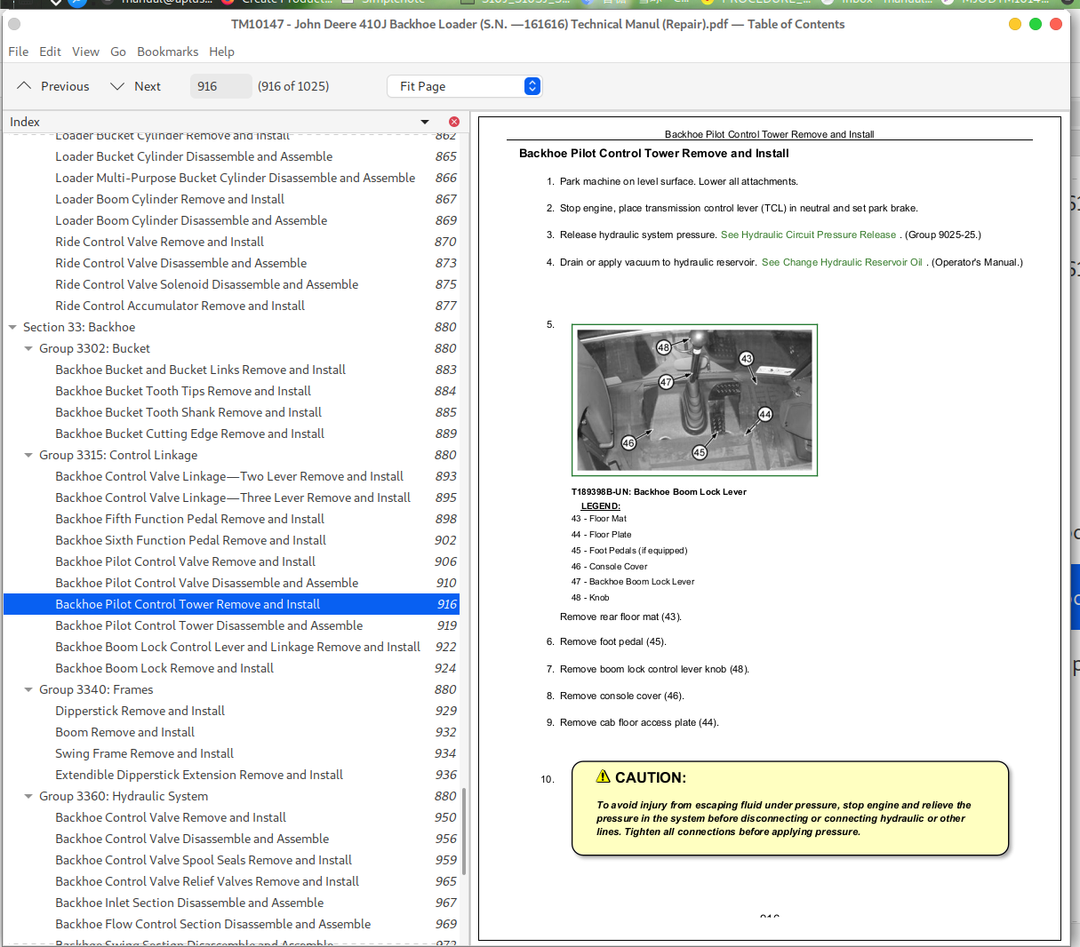
Backhoe Pilot Control Tower Remove and Install.....916
Backhoe Pilot Control Tower Disassemble and Assemble.....919
Backhoe Boom Lock Control Lever and Linkage Remove and Install.....922
Backhoe Boom Lock Remove and Install.....924
Group 3340: Frames.....880
Dipperstick Remove and Install.....929
Boom Remove and Install.....932
Swing Frame Remove and Install.....934
Extendible Dipperstick Extension Remove and Install.....936
Group 3360: Hydraulic System.....880
Backhoe Control Valve Remove and Install.....950
Backhoe Control Valve Disassemble and Assemble.....956
Backhoe Control Valve Spool Seals Remove and Install.....959
Backhoe Control Valve Relief Valves Remove and Install.....965
Backhoe Inlet Section Disassemble and Assemble.....967
Backhoe Flow Control Section Disassemble and Assemble.....969
Backhoe Swing Section Disassemble and Assemble.....972
Backhoe Boom Section Disassemble and Assemble.....975
Backhoe Bucket Section Disassemble and Assemble.....978
Backhoe Crowd Section Disassemble and Assemble.....981
Backhoe Extendible Dipperstick Section Disassemble and Assemble.....984
Backhoe Outlet Section Disassemble and Assemble.....987
Pilot Control Manifold Valve Remove and Install.....989
Pilot Control Manifold Valve Disassemble and Assemble.....991
Pattern Select Valve Remove and Install.....992
Pattern Select Valve Disassemble and Assemble.....995
Backhoe Bucket Cylinder Remove and Install.....997
Backhoe Bucket Cylinder Disassemble and Assemble.....999
Backhoe Crowd Cylinder Remove and Install.....1000
Backhoe Crowd Cylinder Disassemble and Assemble.....1002
Backhoe Boom Cylinder Remove and Install.....1003
Backhoe Boom Cylinder Disassemble and Assemble.....1005
Backhoe Swing Cylinder Remove and Install.....1006
Backhoe Swing Cylinder Disassemble and Assemble.....1009
Backhoe Stabilizer Cylinder Remove and Install.....1010
Backhoe Stabilizer Cylinder Disassemble and Assemble.....1012
Backhoe Extendible Dipperstick Cylinder Remove and Install.....1013
Backhoe Extendible Dipperstick Cylinder Disassemble and Assemble.....1015
Section 99: Dealer Fabricated Tools.....1016
Group 9900: Dealer Fabricated Tools.....1016
DFRW20 Compressor Holding Fixture.....1018
DFT1101 Cab and ROPS Lift Bracket.....1019
DFT1285 Engine Support Bracket.....1020
DFT1286 Backlash Measurement Tool.....1022
John Deere 410J Backhoe Loader (S.N. —161616) Workshop Service Repair Manual - TM10147


