John Deere 310SJ Backhoe Loader (S.N. 159760-) Operation & Test Technical Manual - TM10848
Catalog:
Model:
John Deere 310SJ Backhoe Loader (S.N. 159760-) Workshop Service Repair manual with Electrical Wiring Diagrams (including maintenance, overhaul, disassembling & assembling, adjustment, tune-up, operation, inspecting, diagnosis & troubleshooting…) is divided into different sections. Each section covers a specific component or system with detailed illustrations. A table of contents is placed at the beginning of each section. Pages are easily found by category, and each page is expandable for great detail. The printer-ready PDF documents work like a charm on all kinds of devices.
John Deere 310SJ Backhoe Loader (S.N. 159760-) technical manual contains high quality images, circuit diagrams, instructions to help you to maintenance, troubleshoot, diagnose, and repair. This document is printable, without restrictions, contains searchable text, bookmarks, crosslinks for easy navigation.
TM10848 - John Deere 310SJ Backhoe Loader (S.N. 159760-) Technical Manual (Operation & Test Manual).pdf
TABLE OF CONTENTS / FILE LIST:
TABLE OF CONTENTS......1
Section 9000: General Information......19
Group 01: Safety Information......19
Recognize Safety Information......22
Follow Safety Instructions......23
Operate Only If Qualified......24
Wear Protective Equipment......25
Avoid Unauthorized Machine Modifications......26
Inspect Machine......27
Stay Clear of Moving Parts......28
Avoid High-Pressure Oils......29
Avoid High-Pressure Fluids......30
Beware of Exhaust Fumes......31
Prevent Fires......32
Prevent Battery Explosions......33
Handle Chemical Products Safely......34
Dispose of Waste Properly......35
Prepare for Emergencies......36
Use Steps and Handholds Correctly......37
Start Only From Operator's Seat......38
Use and Maintain Seat Belt......39
Prevent Unintended Machine Movement......40
Prevent Unintended Machine Movement—If Equipped With Pilot Controls......41
Avoid Work Site Hazards......42
Keep Riders Off Machine......44
Avoid Backover Accidents......45
Avoid Machine Tipover......46
Add and Operate Attachments Safely......47
Use Special Care When Operating......48
Operating or Traveling On Public Roads......49
Inspect and Maintain ROPS......50
Prevent Unintended Detonation of Explosive Devices......51
Park and Prepare for Service Safely......52
Service Cooling System Safely......53
Remove Paint Before Welding or Heating......54
Make Welding Repairs Safely......55
Drive Metal Pins Safely......56
Service Tires Safely......57
Section 9001: Diagnostics......58
Group 10: Engine Control Unit (ECU)......58
Engine Control Unit (ECU) Diagnostic Trouble Codes......63
000029.03 - Engine Speed Control Short Circuit......58
000029.04 - Engine Speed Control Open Circuit......58
000029.14 - Engine Speed Control Out of Range......58
000091.03 - Foot Throttle Position Sensor Short Circuit......58
000091.04 - Foot Throttle Position Sensor Open Circuit......58
000091.14 - Foot Throttle Position Sensor Out of Range......58
001075.05 - Fuel Lift Pump Relay Open Circuit......58
001075.06 - Fuel Lift Pump Relay Short Circuit......58
001321.05 - Starter Relay Open Circuit......58
001321.06 - Starter Relay Short Circuit......58
001321.16 - Crank Cycle Too Long......58
002023.09 - Hand Throttle Message Missing (Landscape Loader Only)......58
002047.09 - Can Communication Lost with FLC......58
002071.09 - Hand Throttle Message Missing (Backhoe Only)......58
523702.09 - Flex Power Message Missing......58
Group 20: Flex Load Controller (FLC)......58
Flex Load Controller (FLC) Diagnostic Trouble Codes......100
000069.07 - MFWD Logic Error......58
000070.02 - Park Brake Switch (S7) Open Circuit......58
000070.04 - Park Brake Switch (S7) Short to Ground......58
000070.07 - Park Brake Switch (S7) Logic Error......58
000117.19 - Service Brake Pressure Low......58
000234.02 - Software Revision Mismatch......58
000237.02 - Model Number in Vehicle Identification Number Not Valid......58
000525.03 - TCL/Range Switch (S5) Gear Range Input Shorted to Power......58
000525.04 - TCL/Range Switch (S5) Gear Range Input Voltage Low......58
000525.05 - TCL/Range Switch (S5) Gear Range Input Open Circuit......58
000525.12 - TCL/Range Switch (S5) Gear Range Input Logic Error......58
000629.12 - FLC Watchdog Timeout......58
000734.05 - Transmission Solenoid (Y1) Open Circuit......58
000735.05 - Transmission Solenoid (Y2) Open Circuit......59
000736.05 - Transmission Solenoid (Y3) Open Circuit......59
000737.12 - Transmission Solenoid (Y4 or Y5) Fault......59
000738.05 - Transmission Solenoid (Y5) Open Circuit......59
000739.12 - Transmission Solenoid (Y2 or Y6) Fault......59
000741.12 - Transmission Solenoid (Y1 or Y3) Fault......59
000746.07 - Differential Lock Switch (S4) Logic Error......59
000746.12 - Differential Lock Switch (S4) Short to Power or Ground......59
000757.05 - Transmission Solenoid (Y4) Open Circuit......59
000759.05 - Transmission Solenoid (Y6) Open Circuit......59
001504.05 - Seat Swivel Latch Switch (S18) Short to Ground......59
001714.04 - Seat Position Front Switch (S17) Short to Ground......59
001714.07 - Seat Position Rear Switch (S16) and Seat Position Front Switch (S17) Logic Mismatch......59
001714.10 - Seat Position Front Switch (S17) Short Circuit to Power or Stuck Closed......59
001715.04 - Seat Position Rear Switch (S16) Short to Ground......59
002000.09 - CAN Communication Lost with ECU......59
002023.09 - CAN Communication Lost with SDM......59
002228.09 - CAN Communication Lost with FHC......59
002368.12 - Left Turn Signal Driver Output Fault......59
002370.12 - Right Turn Signal Driver Output Fault......59
002580.07 - Service Brake Pressure Switch Status Error......59
002605.12 - Brake Charge Solenoid (Y59) Circuit Fault......59
002875.04 - 4-Way Flasher Switch (S31) Input Short to Ground......59
002876.12 - Conflicting Turn Signal Switch (S30) Data......59
003413.04 - Right Door Switch (S99) Input Short to Ground......59
003416.03 - Right Exit Switch (S99) Circuits Short to Power......59
003416.04 - Right Exit Switch (S99) Circuits Short to Ground......59
003416.05 - Right Exit Switch (S99) Open Circuit......59
298816.14 - Park Brake Did Not Apply When Commanded......59
522371.04 - FLC Valve Power #5 Voltage Low......59
522379.12 - Park Brake Release Solenoid (Y7) Fault......59
522398.14 - Park Brake Did Not Release When Commanded......59
522411.03 - TCL/Range Switch (S5) Input Voltage High......60
522411.04 - TCL/Range Switch (S5) Input Voltage Low......60
522411.05 - TCL/Range Switch (S5) TCL Input Open Circuit......60
523218.03 - FLC Valve Power #2 Output Stuck ON......60
523218.04 - FLC Valve Power #2 Output Stuck OFF......60
523218.05 - FLC Valve Power #2 Output Voltage Low......60
523219.04 - FLC Valve Power #1 Voltage Low......60
523702.02 - Flex Power Status Erratic......60
523702.07 - Flex Power Not Active......60
523702.08 - Flex Power Time Out......60
523702.09 - Flex Power ECU Authentication Error......60
523702.13 - Flex Power Mismatch......60
523702.10 - Flex Power Watch Dog Error......60
523911.12 - Hydraulic Pump Control Solenoid (Y56) Fault......60
523948.12 - Ride Control Solenoid 1 (Y50) or 2 (Y51) Fault......60
524070.04 - Valve Power # 6 Voltage Low......60
524075.04 - Valve Power # 5 Voltage Low......60
524172.00 - Clutch Disconnect Switch Stuck Closed......60
524172.04 - Switch Short to Ground......60
524172.07 - Clutch Disconnect Device Fault......60
524235.12 - MFWD Solenoid (Y11) Output Fault......60
Group 30: Standard Display Monitor (SDM)......60
Standard Display Monitor (SDM) Diagnostic Trouble Codes......246
000096.03 - Fuel Level Sensor (B8) Input Voltage Low......60
000096.04 - Fuel Level Sensor (B8) Input Voltage High......60
000100.01 - Engine Oil Pressure Low......60
000100.05 - Engine Oil Pressure Switch Open......60
000107.00 - Engine Air Filter Restricted......60
000117.01 - Service Brake Pressure Low......60
000158.00 - System Voltage High......60
000158.01 - System Voltage Low......60
000177.00 - Torque Converter Oil Temperature High......60
000177.03 - Torque Converter Oil Temperature Sensor (B6) Input Voltage High......60
000177.04 - Torque Converter Oil Temperature Sensor (B6) Input Voltage Low......61
000234.02 - Software Revision Mismatch......61
000920.03 - SDM Alarm (H2) Output Voltage High......61
000920.04 - SDM Alarm (H2) Output Voltage Low......61
001196.11 - Antitheft Lock Status Not Detected From ECU......61
001201.11 - Antitheft Unlock Status Not Detected From ECU......61
001508.00 - Hydraulic Oil Temperature Moderately High......61
001508.03 - Hydraulic Oil Temperature Sensor (B10) Input Voltage High......61
001508.04 - Hydraulic Oil Temperature Sensor (B10) Input Voltage Low......61
001508.16 - Hydraulic Oil Temperature High......61
001713.00 - Hydraulic Oil Filter Restricted......61
002003.09 - CAN Communication Lost with FLC......61
002000.09 - CAN Communication Lost with ECU......61
002228.09 - CAN Communication Lost with FHC......61
002071.09 - CAN Communication Lost with Other Controller......61
298887.13 - SDM/ECU Model Number Mismatch......61
523569.04 - FLC Switched and/or Unswitched Power Open Circuit......61
523662.04 - FHC Valve Power Circuit Voltages Low......61
523649.04 - CAN Communication Lost with Hydraulic Controllers......61
523650.04 - CAN Communication Lost with FHC......61
523653.04 - Gear Selection/Transmission Direction Circuit Voltages Low......61
523665.04 - FLC Valve Power 1 Input Voltage Low......61
523666.04 - FLC Switched Power Voltage Open Circuit......61
Section 9005: Operational Checkout Procedure......349
Group 10: Operational Checkout Procedure......349
Operational Checkout Procedure......349
Section 9010: Engine......376
Group 05: Theory of Operation......376
PowerTech™ and PowerTech E™ 4.5L (4045) John Deere Engines......397
Engine Cooling System......379
Group 15: Diagnostic Information......376
PowerTech™ and PowerTech E™ 4.5L (4045) John Deere Engines......397
Engine Identification......382
Engine Cooling System Component Location......386
Engine Fuel System Component Location......388
Engine Intake and Exhaust Component Location......392
Group 20: Adjustments......376
PowerTech™ and PowerTech E™ 4.5L (4045) John Deere Engines......397
Group 25: Tests......376
PowerTech™ and PowerTech E™ 4.5L (4045) John Deere Engines......397
Fluid Sampling Procedure—If Equipped......398
Engine Speed Check......403
Intake Manifold Pressure—Turbocharger Boost......405
Air Intake System Leakage Test......409
Air in Fuel Test......411
Engine Thermostat Test......412
Thermal Bypass Valve Test......413
Section 9015: Electrical System......414
Group 05: System Information......414
Electrical Diagram Information......421
Electrical Schematic Symbols......425
Group 10: System Diagrams......414
Fuse and Relay Location and Specifications......431
System Functional Schematic, Wiring Diagram, and Component Location Legend......434
System Functional Schematic and Section Legend......441
System Functional Schematic, Wiring Diagram, and Component Location Legend—Stage II Engine......445
System Functional Schematic and Section Legend—Stage II Engine......452
JDLink™ System Functional Schematic—MIG/GTT......460
JDLink™ System Functional Schematic—MTG/SAT......462
Canopy (ROPS) Harness (W5) Component Location......464
Canopy (ROPS) Harness (W5) Wiring Diagram......466
Engine Harness (W7) Component Location......470
Engine Harness (W7) Wiring Diagram......473
Transmission Harness (W9) Component Location......476
Transmission Harness (W9) Wiring Diagram......477
Cab Harness (W10) Component Location......478
Cab Harness (W10) Wiring Diagram......480
Roof Harness (W15) Component Location......484
Roof Harness (W15) Wiring Diagram......485
Air Conditioning Harness (W16) Component Location......487
Air Conditioning Harness (W16) Wiring Diagram......489
Selective Flow Control Harness (W17) Component Location......491
Selective Flow Control Harness (W17) Wiring Diagram......493
Ride Control Harness (W18, W19) Component Location......495
Ride Control Harness (W18, W19) Wiring Diagram......497
Radio Harness (W20) Component Location......499
Radio Harness (W20) Wiring Diagram......500
Loader Coupler Harness (W21, W22) Component Location......501
Loader Coupler Harness (W21, W22) Wiring Diagram......503
Pilot Control Harness (W23, W24) Component Location (S.N. —178748)......505
Pilot Control Harness (W23, W24) Wiring Diagram (S.N. —178748)......507
Pilot Control Harness (W24, W47, W48) Component Location (S.N. 178749— )......509
Pilot Control Harness (W24, W47, W48) Wiring Diagram (S.N. 178749— )......511
Return-to-Dig Harness (W25) Component Location......514
Return-to-Dig Harness (W25) Wiring Diagram......515
Pump Control Harness (W26) Component Location......516
Pump Control Harness (W26) Wiring Diagram......517
JDLink™ System Harnesses Component Location—MIG/GTT......518
JDLink™ System Harnesses Component Location—MTG/SAT......520
JDLink™ System Wiring Diagrams—MIG/GTT......522
JDLink™ System Wiring Diagrams—MTG/SAT......525
Diode Suppression Harness (W33) Wire Diagram—If Equipped......528
Diode Suppression Harness (W33) Component Location—If Equipped......529
Water-in-Fuel (WIF) Harnesses (W40, W41) Component Location......530
Water-in-Fuel (WIF) Harnesses (W40, W41) Wiring Diagram......531
Group 15: Sub-System Diagnostics......415
Start and Charge Circuit Theory of Operation......536
Start and Charge Circuit Theory of Operation—Stage II Engine......539
Controller Area Network (CAN) Circuit Theory of Operation......541
Engine Control Unit (ECU) Circuit Theory of Operation......543
Engine Control Unit (ECU) Circuit Theory of Operation—Stage II Engine......549
Flex Load Controller (FLC) Circuit Theory of Operation......552
Standard Display Monitor (SDM) Circuit Theory of Operation......559
JDLink™ Circuit Theory of Operation—If Equipped......563
Group 16: Monitor Operation......415
Standard Display Monitor (SDM)—Service Menu......566
Standard Display Monitor (SDM)—Clear Codes......567
Standard Display Monitor (SDM)—Diagnostics......568
Standard Display Monitor (SDM)—Hide/Unhide Main Menu......571
Standard Display Monitor (SDM)—Restore Monitor Defaults......572
Standard Display Monitor (SDM)—Machine Options......573
Standard Display Monitor (SDM)—Setting Hour Meter......574
Anti-Theft Security System Enable/Disable......576
Anti-Theft Security System Configuration......578
Anti-Theft Security System Operation......582
Group 20: References......416
Service ADVISOR™ Connection Procedure......586
JDLink™ System Identification......588
JDLink™ Connection Procedure—If Equipped......591
Reading Diagnostic Trouble Codes (DTCs)......592
Diagnostic Trouble Code (DTC) Monitor Messages......595
Intermittent Diagnostic Trouble Code (DTC) Diagnostics......596
Controller Area Network (CAN) Resistor Test......597
Controller Area Network (CAN) Circuit Test......599
Alternator Test Procedure......608
Electrical Component Specifications......609
Wire Harness Test......612
Sensor Circuit Check......613
Crank Position Sensor Test......615
Throttle Position Sensor Test......616
Flex Load Controller (FLC) Output Test......617
Transmission Solenoid Circuit Test......618
Transmission Control Circuit Test......619
Transmission Control Lever (TCL) Test......621
Transmission Solenoid Check......623
Seat Position Switches Remove and Install......624
WEATHER PACK® Connector Remove and Install......625
WEATHER PACK® Contact Installation......627
DEUTSCH® Connector Remove and Install......629
DEUTSCH® Contact Installation......633
CINCH™ Connector Remove and Install......635
CINCH™ Contact Installation......637
CINCH™ CP Connector Remove and Install......639
CINCH™ CP Contact Installation......648
Metri-Pack® Connector Remove and Install......652
Section 9020: Power Train......655
Group 05: Theory of Operation......655
Power Shift Power Train Overview......660
Clutch Modulation Operation......662
Torque Converter Operation......664
Transmission Pump Operation......666
Transmission Filter Operation......667
Clutch and Mechanical Front Wheel Drive (MFWD) Operation......668
Power Shift Transmission Gear Flow......670
Power Shift Transmission Clutch Engagement and Solenoids Activated......673
Differential Operation......674
Differential Lock Operation......676
MICO Power Boost Brake Valve—Neutral Position......678
MICO Power Boost Brake Valve—Both Pedals Applied Position......680
MICO Power Boost Brake Valve—One Pedal Applied Position......682
MICO Power Boost Brake Valve—Both Pedals Applied, Engine Off Position......684
Service Brake Operation......686
Park Brake Operation......687
MFWD Differential Operation—Unequal Traction......689
MFWD Differential Operation—Equal Traction—If Equipped......691
Group 15: Diagnostic Information......655
Power Train Component Location......695
Hydraulic Circuit—Symbols......698
Power Train Schematic—Neutral......699
Power Train Schematic—First Forward Mechanical Front Wheel Drive (MFWD) Engaged......701
Power Train Schematic—First Reverse......703
Power Train Schematic—Fourth Forward......705
Diagnose Transmission Malfunctions......707
Transmission Slippage......655
Machine Lacks Power or Moves Slow......655
Transmission Overheats......655
Excessive Power Train Noise......655
Park Brake Piston Leak......655
No Power to Mechanical Front Wheel Drive (MFWD)......656
No Power to One Wheel of Mechanical Front Wheel Drive (MFWD)......656
No Differential Lock Operation......676
Differential Lock Slips or Chatters When Engaged......656
Differential Lock Will Not Release......656
Rear Axle Overfilled With Oil......656
Poor Service Brakes......656
Brake Pedal Hard to Push......656
Service Brakes Will Not Release......656
Service Brakes Chatter or Noisy......656
Park Brake Will Not Hold......656
Park Brake Will Not Release......656
Group 20: Adjustments......656
Park Brake Release for Towing......758
Brake Pedal Adjustment......760
Brake Bleeding Procedure......762
Tracking Angle Check and Adjust......766
Toe-In Check and Adjust......767
Steering Angle Check and Adjust......769
Group 25: Tests......656
Transmission Oil Warm-Up Procedure......772
Transmission Oil Sampling Procedure—If Equipped......774
Power Shift Transmission Overall Test Connections, Ports, and Locations......775
Torque Converter Stall Speed Test......777
Torque Converter Inlet Pressure Test......780
Brake Valve Leakage Test......785
Park Brake Release Pressure Test......787
Transmission System Pressure Test......789
Service Brake Boost Pressure Test......792
Clutch Pressure Test......795
Differential Lock Pressure Test......798
Mechanical Front Wheel Drive (MFWD) Pressure Test......800
Cooler In and Cooler Out Pressure Test......802
Solenoid Circuit Leakage Test......806
Transmission Pump Flow Test......807
Section 9025: Hydraulic System......809
Group 05: Theory of Operation......809
Hydraulic System Operation......815
Hydraulic Pump Operation......817
Unloading Valve Operation......819
Hydraulic Filter Operation......823
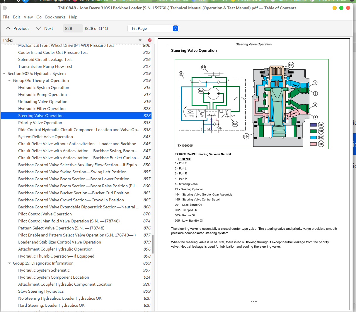
Steering Valve Operation......828
Priority Valve Operation......833
Ride Control Hydraulic Circuit Component Location and Valve Operation......838
System Relief Valve Operation......843
Circuit Relief Valve without Anticavitation—Loader and Backhoe......845
Circuit Relief Valve with Anticavitation—Backhoe Swing, Boom Lower......847
Circuit Relief Valve with Anticavitation—Backhoe Bucket Curl and Loader Bucket Dump......848
Backhoe Control Valve Selective Auxiliary Flow Section—If Equipped......850
Backhoe Control Valve Swing Section—Swing Left Position......855
Backhoe Control Valve Boom Section—Boom Lower Position......857
Backhoe Control Valve Boom Section—Boom Raise Position (Pilot Control)......860
Backhoe Control Valve Bucket Section—Bucket Curl Position......863
Backhoe Control Valve Crowd Section—Crowd In Position......865
Backhoe Control Valve Extendable Dipperstick Section—Neutral Position with Upstream Function Activated......868
Pilot Control Valve Operation......870
Pilot Control Manifold Valve Operation (S.N. —178748)......874
Pattern Select Valve Operation (S.N. —178748)......876
Pilot Enable and Pattern Select Valve Operation (S.N. 178749— )......877
Loader and Stabilizer Control Valve Operation......879
Attachment Coupler Hydraulic Operation......896
Hydraulic Thumb Operation—If Equipped......898
Group 15: Diagnostic Information......809
Hydraulic System Schematic......907
Hydraulic System Component Location......914
Attachment Coupler Hydraulic Component Location......920
Slow Steering Hydraulics......809
No Steering Hydraulics, Loader Hydraulics OK......810
Hard Steering, Loader Hydraulics OK......810
Steering Valve Does Not Return to Neutral......810
No Response when Steering Wheel is Turned, Loader Hydraulics OK......810
Machine Turns in Opposite Direction......810
Excessive Vibration of the Steering Wheel......810
Machine Turns when Steering Valve is in Neutral......810
Steering Wheel Kickback......810
Excessive Steering Wheel Turns To Steer Machine......810
Erratic (“Spongy”) Steering......810
Steering Wheel "Locks" Up......810
Poor Centering of Steering Wheel (Wheels Continue to Move After Steering Wheel is Stopped)......810
Steering Wheel or Front Wheels Slowly Turn by Themselves When Using Backhoe or Loader......810
Steering Wheel Turns Apply Rear Axle Service Brakes......810
Steering Wheel Turns Freely With No Resistance or Action On Steered Wheels......810
Steering Wheel Turns With Slight Resistance and No Action On Steered Wheels......810
Wander—Vehicle Will Not Stay in a Straight Line......810
No Loader or Steering Hydraulics......810
No Loader Hydraulics......810
Low Loader Hydraulic Power......810
Low Hydraulic Power......810
Engine Pulls Down Excessively During Loader Operation......810
Engine Pulls Down Excessively During Backhoe Operation......810
Slow Hydraulic Functions......810
Loader or Backhoe Operates Slowly in One Function......810
No Loader or Backhoe Power in One Function......810
No Stabilizer Hydraulics......810
Slow Loader and Backhoe Hydraulics......810
Low Hydraulic Power (Low Hydraulic Pressure)......810
Hydraulic Function Makes "Chattering" Noise......810
Functions Drift......810
Control Valve Sticks or Works Hard......810
Hydraulic Oil Overheats......810
Foaming Oil......811
Hydraulic Pump Leaking......811
Excessive Pump Noise......811
Attachment Coupler Not Working......811
Group 20: Adjustments......811
Loader Bucket Self-Leveling Linkage and Return-To-Dig Switch Adjustment......1000
Loader Lever and Stabilizer Lever Adjustment......1004
Backhoe Control Lever to Valve Linkage (Two Lever) Adjustment......1008
Backhoe Control Lever to Valve Linkage (Four Lever) Adjustment—If Equipped......1011
Auxiliary Flow Control Valve Adjustment—If Equipped......1014
Ride Control Accumulator Charge Procedure......1016
Ride Control Accumulator Charge Check Procedure......1019
Ride Control Accumulator Hydraulic Pressure Release Procedure......1021
Pilot Control Pressure Adjustment......1022
Pilot Control Manifold Valve Accumulator Discharge Procedure......1027
Pilot Enable and Pattern Select Valve Accumulator Discharge Procedure......1028
Group 25: Tests......811
JT02156A Digital Pressure and Temperature Analyzer Kit Installation......1030
Hydraulic Oil Warmup Procedure......1031
Hydraulic Oil Sampling Procedure—If Equipped......1032
Hydraulic Circuit Pressure Release......1033
Hydraulic Pump Flow Test......1035
Backhoe Relief Valve Pressure Test......1039
Steering Load Sense Relief Valve Pressure Test......1042
Hydraulic Pump Unloading Relief Valve Pressure Test......1044
Pilot Control Pressure Test......1047
Pilot Control Accumulator Charge Pressure Test......1048
Hydraulic Oil Cooler Restriction Test......1051
Circuit Relief Valve Test—With Remote Pump......1054
Steering System Leakage Test......1058
Steering Cylinder Leakage Test......1061
Function Drift Test......1063
Hydraulic Cylinder Leakage Test......1072
Loader and Stabilizer Control Valve Lockout Leakage Test......1075
Section 9031: Heating and Air Conditioning......1077
Group 05: Theory of Operation......1077
Proper Refrigerant Handling......1115
R134a Refrigerant Cautions......1116
R134a Refrigerant Theory Of Operation......1082
Air Conditioning Circuit Specifications......1084
Air Conditioning Circuit Operational Information......1085
Air Conditioning Circuit Theory of Operation......1086
Freeze Control Switch Operation......1087
Receiver/Dryer Operation......1088
Expansion Valve Operation......1090
Compressor Relief Valve Operation......1091
Heater Blower Circuit Operational Information......1092
Heater Blower Circuit Theory Of Operation......1093
Temperature Control Operation......1094
Group 15: Diagnostic Information......1077
Air Conditioning System Does Not Operate......1077
Air Conditioner Does Not Cool Interior of Cab......1077
Air Conditioner Runs Constantly, Too Cold......1077
Interior Windows Continue to Fog......1077
Heater System Does Not Operate......1077
Heater Does Not Warm Interior of Cab......1077
Air Conditioning and Heater System Component Location......1112
Group 25: Tests......1077
Proper Refrigerant Handling......1115
R134a Refrigerant Cautions......1116
R134a Air Conditioning System Test......1117
Operating Pressure Diagnostic Chart......1120
Expansion Valve Operation Test......1125
Blower Switch Test......1128
Blower Resistor Test......1129
Heater Blower Motor Test......1131
Freeze Control Switch Test......1132
Air Conditioning Switch Test......1133
Binary Pressure Switch Test......1134
Compressor Clutch Coil Test......1137
Air Conditioning System Leak Test......1138
Refrigerant Hoses And Tubing Inspection......1139
John Deere 310SJ Backhoe Loader (S.N. 159760-) Operation & Test Technical Manual - TM10848


