John Deere S560 STS and S690 STS Combines Workshop Service Repair Manual - tm102719
Catalog:
Model:
John Deere S560 STS and S690 STS Combine Workshop Service Repair manual (including maintenance, overhaul, disassembling & assembling, adjustment, tune-up, operation, inspecting…) is divided into different sections. Each section covers a specific component or system with detailed illustrations. A table of contents is placed at the beginning of each section. Pages are easily found by category, and each page is expandable for great detail. The printer-ready PDF documents work like a charm on all kinds of devices.
S560 STS and S690 STS Combine repair manual contains high quality images, instructions to help you to maintenance, troubleshoot, diagnose, and repair. This document is printable, without restrictions, contains searchable text, bookmarks, crosslinks for easy navigation.
tm102719 - S560 STS and S690 STS Combine Repair Technical Manual.pdf
tm102719 - S560 STS and S690 STS Combine Repair Technical Manual.epub
TABLE OF CONTENTS / FILE LIST:
Section 10: General................33
Group 05: Safety................33
Recognize Safety Information................37
Understand Signal Words................38
Remove Paint Before Welding or Heating................39
Handle Fluids Safely—Avoid Fires................40
Prevent Battery Explosions................232
Handling Batteries Safely................233
Prepare for Emergencies................44
Prevent Acid Burns................45
Avoid High-Pressure Fluids................47
Service Accumulator Systems Safely................48
Wait Before Opening High-Pressure Fuel System................49
Park Machine Safely................50
Support Machine Properly................51
Wear Protective Clothing................52
Service Machines Safely................53
Work In Ventilated Area................54
Illuminate Work Area Safely................55
Replace Safety Signs................56
Use Proper Lifting Equipment................57
Service Tires Safely................1034
Avoid Harmful Asbestos Dust................59
Work in Clean Area................60
Practice Safe Maintenance................61
Use Proper Tools................62
Construct Dealer-Made Tools Safely................63
Avoid Heating Near Pressurized Fluid Lines................64
Decommissioning — Proper Recycling and Disposal of Fluids and Components................65
Use Adequate Service Facilities................66
Live With Safety................67
Servicing Electronic Control Units................68
Precautions for Welding................69
Keep Electronic Control Unit Connectors Clean................71
Group 10: Specifications................2270
Operating Speeds—S560 STS™................74
Operating Speeds—S690 STS™................76
Specifications—S560 STS™................79
Specifications—S690 STS™................82
Dimensions—S560 STS™................85
Dimension Reference Points—S560 STS™................86
Dimensions—S690 STS™................87
Dimension Reference Points—S690 STS™................89
Unified Inch Bolt and Screw Torque Values................90
Metric Bolt and Screw Torque Values................93
Sealants and Adhesives Cross-Reference Chart................95
Face Seal Fittings Assembly and Installation—All Pressure Applications................97
Metric Face Seal and O-Ring Stud End Fitting Torque Chart—Standard Pressures................98
Metric Face Seal and O-Ring Stud End Fitting Torque Chart—High Pressure Applications................100
SAE Face Seal and O-Ring Stud End Fitting Torque Chart—Standard Pressures................102
SAE Face Seal and O-Ring Stud End Fitting Torque Chart—High Pressure Applications................104
Four Bolt Flange Fittings Assembly and Installation—All Pressure Applications................106
SAE Four Bolt Flange Cap Screw Torque Values—Standard Pressure Applications................107
SAE Four Bolt Flange Cap Screw Torque Values—High Pressure Applications................108
Group 15: Tune-Up and Adjustment................111
Tune-Up and Adjustment................111
Care and Maintenance of Belts................113
Defective Belts................115
Prevent Hydraulic System Contamination................118
Check Oil Lines and Fittings................119
Basic Electrical Component Handling / Precautions For Vehicles Equipped With Computer Controlled Systems................120
Programming Control Units................121
Group 20: Fuels and Lubricants................34
Handle Fuel Safely—Avoid Fires................125
Handling and Storing Diesel Fuel................127
Diesel Fuel................127
BioDiesel Fuel................129
Lubricity of Diesel Fuel................131
Testing Diesel Fuel................132
Diesel Engine Coolant (engine with wet sleeve cylinder liners)................133
Operating in Warm Temperature Climates................135
Supplemental Coolant Additives................136
Additional Information About Diesel Engine Coolants and John Deere LIQUID COOLANT CONDITIONER................137
Testing Diesel Engine Coolant................139
Diesel Engine Break-In Oil — Non-Emissions Certified and Certified Tier 1, Tier 2, Tier 3, Stage I, Stage II, and Stage III................140
Diesel Engine Oil — Tier 3 and Stage III................142
Oilscan™ and CoolScan™................144
Hydrostatic Drive System, Main Hydraulic System and Main Engine Gear case Oils................145
Transmission (Non Two Range Automatic Transmission Machines), Final Drives, Loading Auger, Primary Countershaft and Two-Speed Separator Drive Gear Cases................146
Feeder House Reverser Gear Case................148
Grease................149
Brake Fluid................150
Lubricant Storage................151
Alternative and Synthetic Lubricants................152
Mixing of Lubricants................153
Section 20: Engine................154
Group 05: Remove and Install Engine................154
Essential or Recommended Tools................2266
Specifications................2270
John Deere Engine Repair—Use CTM................205
Remove Engine—9.0 L................154
Install Engine—9.0 L................154
Remove Engine—13.5 L................154
Install Engine—13.5 L................154
Remove and Install Flywheel Pilot Bearing................175
Group 10: Cooling System................154
Essential or Recommended Tools................2266
Specifications................2270
John Deere Engine Repair—Use CTM................205
Rotary Screen Drive................181
Remove and Install Rotary Screen Idler Arm and Sheaves................183
Remove and Install Upper and Lower Air Scoops................184
Remove and Install Rotary Screen................186
Adjusting Rotary Screen Knife Comb................189
Remove Radiator—9.0 L and 13.5 L Engines................154
Install Radiator—9.0 L and 13.5 L Engines................154
Test Radiator................197
Test Radiator Cap................198
Replace Thermostats................199
Repair or Replace Water Pump................200
Section 30: Fuel and Air Repair................201
Group 05: Air Intake System................201
Other Material................2269
Specifications................2270
John Deere Engine Repair—Use CTM................205
Remove and Install Turbocharger................206
Turbocharger Repair................207
Remove and Install Charge Air Cooler................208
Cleaning Charge Air Cooler................213
Group 10: Diesel Fuel System................201
Other Material................2269
Specifications................2270
Remove and Install Fuel Tank Shut-Off Valve and Drain Valve................217
Remove and Install Fuel Prefilter................220
Remove and Install Fuel Tank................221
Remove and Install Fuel Tank Strainer and Breather................224
Section 40: Electrical System................226
Group 05: Batteries................226
Prevent Battery Explosions................232
Handling Batteries Safely................233
Prevent Damage to Electrical Systems................235
Checking Electrolyte Specific Gravity................236
Battery Replacement................238
Remove and Install Batteries................239
Connecting Booster Batteries................242
Charging Batteries................243
Connecting Battery Cables................245
Group 10: Harness and Connector Repair................226
Essential or Recommended Tools................2266
Other Material................2269
Use Electrical Insulating Compound................257
Using High-Pressure Washers................258
Electrical System Visual Inspection................259
Basic Electrical Component Handling / Precautions for Vehicles Equipped with Computer Controlled Systems................260
Electrical Connector / Wiring Harness Handling and Repair................261
Repair Procedure R-A................262
Repair Procedure R-B................267
Repair Procedure R-C................271
Repair Procedure R-D................276
Repair Procedure R-E................279
Repair Procedure R-F................283
Repair Procedure R-G................287
Repair Procedure R-I................290
Repair Procedure R-J................293
Repair Procedure R-K................298
Repair Procedure R-M................301
Repair Procedure R-N................305
Repair Procedure R-AE................309
Repair Procedure R-AF................313
Repair Procedure R-AG................316
Repair Procedure R-AH................319
Repair Procedure R-AI................321
Repair Procedure R-AJ................324
Repair Procedure R-AK................329
Repair Procedure R-AL................332
Group 15: Wire Harness Routing................227
Replace Harness................337
Cab Main Wiring Harness................338
Left-Hand Main Wiring Harness................339
LC1 Wiring Harness................340
LC2 Wiring Harness................341
Right-Hand Main Wiring Harness................342
Engine Deck Wiring Harness................343
Group 20: Power Distribution................227
Fuse Identification................346
Remove and Install Cab Power Module (CPM)................348
Remove and Install Right and Left Power Modules................349
Group 25: Lighting................227
Safety Rules When Replacing Halogen Bulbs................351
Safety Rules When Replacing High Intensity Discharge (HID) Xenon Bulbs................352
Cab Head Light Bulb Replacement and Adjustment................353
Remove and Install High Intensity Discharge (HID-Xenon) Lights (Optional)................355
Remove and Install High Intensity Discharge (HID-Xenon) Ballasts................358
Auxiliary Field, Access Door, Grain Tank, Unload Auger and Work Light Bulb Replacement................359
Side Finder (Optional) Light Bulb Replacement................360
Hazard/Warning Light Bulb Replacement................361
Cleaning Shoe Light Bulb Replacement................363
Turn Signal Light Bulb Replacement................364
Dome Light Bulb Replacement................365
Group 30: Operators Station................227
Other Material................2269
Specifications................2270
Instruments And Controls Identification................369
Remove and Install Overhead Panel................371
Remove and Install Right-Hand Overhead Panel................373
Remove and Install Light Panel Dimmer Switch................374
Remove and Install Overhead Panel and Right-Hand Overhead Panel Rocker Switches................375
Remove and Install ClimaTrak ClimaTrak is a trademark of Deere & Company Automatic Air Conditioning/Heater Temperature Control Switch and Fan Switch................228
Remove and Install Radio................378
Remove and Install Radio Speaker................380
Remove and Install Radio Antenna................381
Replace Cornerpost Main Circuit Board................383
Remove Header Control Module................387
Remove VisionTrak VisionTrak is a trademark of Deere & Company Module and Digital Tachometer Module................228
CommandTouch Console Controls................389
Remove and Install CommandTouch Console................391
Remove and Install Armrest Display Unit................393
Remove and Install Header and Separator Engage Switches................394
Remove and Install Backlighting Driver................395
Remove and Install Dial-A-Speed and Active Header Control Switches................397
Remove and Install CommandTouch Console Switch Panel................399
Replace Neutral Safety Switch................402
Remove and Install Multi-Function Handle................404
Remove and Install Start Switch................406
Remove and Install Starting Aid Switch................408
Remove and Install Turn Signal/Side Finder Light Switch................409
Remove and Install Horn Switch................410
Remove and Install Remote Mirrors—Style A (Optional)................411
Remove and Install Remote Mirrors—Style B (Optional)................412
Remove and Install Remote Mirror Switch (Optional)................414
Group 35: Sensors and Switches................228
Essential or Recommended Tools................2266
Other Material................2269
Specifications................2270
Shaft Speed Sensor Locations................419
Remove and Install Ground Speed Sensor................421
Remove and Install Low Shaft Speed Sensor................422
Remove and Install STS Rotor Speed Sensor................423
Remove and Install Full Grain Tank Sensor................425
Remove and Install Straw Spreader Speed Sensor................426
Remove and Install Tailings Sensor................430
Remove and Install (Shoe/Separator) VisionTrak VisionTrak is a trademark of Deere & Company Sensors................229
Remove and Install Concave Position Sensor................432
Remove and Install Header Height and Lateral Tilt Control Sensors................435
Remove and Install Header Height and Lateral Tilt Control Sensors................435
Remove And Install Multi-Function Handle Feed Rate Sensor................437
Remove and Install Hydraulic Reservoir Temperature Sensor................444
Remove and Install Coolant Temperature Sensor................445
Remove and Install Fuel Level Sensor................448
Remove and Install Park Brake Switch................449
Remove and Install Air Filter Restriction Switch................450
Remove and Install Fuel Transfer Pump Pressure Sensor—9.0 L Engine................451
Remove and Install High and Low Fuel Pressure Sensors—13.5 L Engine................452
Remove and Install Engine Gear Case Temperature and Pressure Switches................453
Remove and Install Hydro Charge Pressure Switch................454
Remove and Install Engine Oil Pressure Sensor................455
Remove and Install Compressor Inlet Temperature Sensor................456
Remove and Install Pump Position Sensor—9.0 L Engine................457
Remove and Install Cam Position Sensor—13.5 L Engine................458
Remove and Install Engine Speed Sensor................459
Remove and Install Exhaust Gas Recirculation (EGR) Exhaust Gas Temperature and Fresh Air Temperature Sensors................460
Remove and Install Intake Manifold Pressure and Exhaust Gas Recirculation (EGR) Mixed Gas Temperature Sensor................462
Remove and Install Turbocharger Speed Sensor................463
Remove and Install Fuel Temperature Sensor................464
Remove and Install Fuel Rail Pressure Sensor—9.0 L Engine................465
Remove and Install Switches in the Ground Level Switch Bank................466
Remove and Install Back-Up Alarm Switch................467
Back-Up Alarm—S690 STS™................468
Back-Up Alarm—S560 STS™................469
Remove and Install Wheel Angle Sensor................470
Group 40: Wiper................230
Specifications................2270
Remove And Install Wiper Motor................477
Adjust Windshield Wiper................481
Remove and Install Windshield Washer................483
Group 45: Alternator................230
Essential or Recommended Tools................2266
Specifications................2270
John Deere Engine Accessories—Alternator Repair................488
Remove and Install Alternator and Alternator Belt................489
Remove and Install Alternator Pulley................491
Group 50: Starting Motor................230
Essential or Recommended Tools................2266
Specifications................2270
John Deere Starting Motor Repair................495
Remove and Install Starting Motor................496
Group 55: GreenStar Components................230
Specifications................2270
Other Material................2269
Remove and Install GreenStar Mass-Flow Sensor................502
Remove and Install GreenStar Moisture Sensor................506
Disassemble and Assemble GreenStar Moisture Sensor................507
Remove and Install GreenStar Moisture Sensor Actuator................509
Remove and Install GreenStar Moisture Sensor Circuit Board................513
Remove and Replace GreenStar Moisture Sensor Lower Cell Assembly................515
Disassemble and Assemble Position Receiver................531
Remove and Install Position Receiver................533
Section 50: Power Train Repair................534
Group 05: Transmission and Differential—Three Speed Transmission................534
Other Material................2269
Specifications................2270
Remove and Repair Shifter Forks and Shifter Cam................542
Install Shifter Forks and Shifter Cam................544
Remove and Install Transmission Lube Pump................547
Remove and Install Suction Screen................550
Remove Transmission................551
Transmission Recondition................555
Disassemble and Repair Transmission................556
Assemble Transmission................565
Install Transmission................569
Remove and Install Gearshift Lever and Linkage................572
Adjust Gearshift Linkage................574
Group 10: Hydrostatic System—Three Speed Transmission................534
Essential or Recommended Tools................2266
Service Equipment and Tools................1886
Other Material................2269
Specifications................2270
Serial Number Plate................837
Clean Hydrostatic Motor and Pump................584
Flushing the Hydrostatic System................585
Remove and Install Hydrostatic Motor................586
Disassemble Hydrostatic Motor................588
Inspect Parts................599
Lack of Lubrication................600
Abrasive Contamination................601
Cavitation................602
Over Speeding................603
Inspect Thrust Plate................604
Inspect Fixed Swashplate................605
Inspect Piston Slipper................606
Inspect Piston Retainer................608
Inspect Cylinder Block................610
Inspect Bearing Plate................611
Inspect Valve Plate................614
Inspect Bearing and Race................617
Inspect Servo Piston................618
Inspect Drive Shaft................619
Replace Cylinder Block Spring................620
Assemble Motor................621
Remove and Install Motor Valve Block (Manifold)................635
Repair Motor Valve Block................637
Remove and Install Hydrostatic Pump................639
Disassemble Drive Pump................643
Assemble Drive Pump................660
Replace High-Pressure Line Center Pivot O-Rings................680
Disassemble and Assemble End Cover................681
Repair Displacement Control Valve................683
Disassemble and Assemble DisplacementControl Valve with Feed Rate (Optional)................535
Electronic Proportional Displacement Control Valve Neutral Adjustment................687
Remove and Install Charge Pump................691
Repair Charge Pump................693
Remove and Install Control Cable................695
Adjust Hydrostatic Neutral Linkage................697
Adjust Mechanical Displacement Control Valve Neutral................698
Start-Up Procedure After Hydrostatic System Repair................700
Group 15: Transmission and Differential—Two-Range Automatic Transmission................535
Essential or Recommended Tools................2266
Other Material................2269
Specifications................2270
Drain Oil................722
Remove Two-Range Automatic Transmission................723
Transmission Components—Overview................729
Disassemble Two-Range Automatic Transmission................731
Remove Brake Assemblies................734
Brake Assemblies—Exploded View................737
Disassemble Brake Assemblies................739
Assemble Brake Assemblies................745
Install Brake Assemblies................753
Remove Differential Module................756
Disassemble Differential Module (With Differential Lock)................760
Differential Module (With Differential Lock)—Exploded View................766
Assemble Differential Module (With Differential Lock)................768
Install Differential Module................776
Remove Gear-Shift Planetary Drive With Clutch (Forward/Reverse)................779
Disassemble and Assemble Gear-Shift Planetary Drive With Clutch (Forward/Reverse)................784
Install Gear-Shift Planetary Drive With Clutch (Forward/Reverse)................807
Remove Countershaft................814
Repair Countershaft................817
Countershaft—Exploded View................820
Install Countershaft................821
Assemble Two-Range Automatic Transmission................826
Install Two-Range Automatic Transmission................829
Group 20: Hydrostatic Drive Pump—Two-Range Automatic Transmission................536
Specifications................2270
General View................896
Serial Number Plate................837
Clean Variable Pump................838
Remove And Install Hydrostatic Pump................839
Replace Drive Shaft Seal................842
Replace Boost Pump Seal................847
Replace Control Piston Cover Seals................850
Replace Boost Pressure Valve Seals................854
Replace Pressure Cut Off Valve Seals................855
Remove and Install Control Unit................856
Disassemble Pump................860
Disassemble Cylinder Assembly................866
Disassemble Control Piston................868
Hydrostatic Drive Pump Inspection Notes................916
Assemble Pump................875
Install Rotary Group................882
Adjust Zero Position................888
Group 25: Hydrostatic Drive Motor—Two-Range Automatic Transmission................537
Essential or Recommended Tools................2266
Specifications................2270
Remove and Install Hydrostatic Drive Motor................893
General View................896
Replace Cover Plate Seal................897
Replace Control Body Seals................899
Disassemble Port Plate................901
Assemble Port Plate................907
Disassemble Rotary Group................910
Inspection Notes................916
Assemble Rotary Group................920
Adjust Rotary Group................928
Group 30: Single Reduction Final Drive................537
Essential or Recommended Tools................2266
Service Equipment and Tools................1886
Other Material................2269
Specifications................2270
Remove and Install Final Drive................938
HILLMASTER Left-Hand Rocker Assembly—Exploded View................944
HILLMASTER Right-Hand Rocker Assembly—Exploded View................946
Disassemble and Assemble Final Drive................948
Adjust Spindle Bearing................961
Group 35: Cam Lobe Motor................537
Essential or Recommended Tools................2266
Service Equipment and Tools................1886
Other Material................2269
Specifications................2270
Flushing Cam Lobe Motors................973
Remove Cam Lobe Motor................974
Install Cam Lobe Motor................976
Remove and Install Cam Lobe Motor Control Valve................978
Disassemble and Assemble Cam Lobe Motor Control Valve................981
Remove and Install Steering Yoke................983
Disassemble and Assemble Pivot Pins, Bushings, and Seals................991
Remove and Install Solenoid Valve and Valve Block................994
Remove and Install Displacement Control Valve................999
Remove and Install Cam and Piston Carrier................1002
Remove and Install Stack Valve Seals................1009
Remove and Install Axle Bearings and Seals................1014
Group 40: Tires and Wheels................538
Essential or Recommended Tools................2266
Service Equipment and Tools................1886
Specifications................2270
Tire Identification................1032
Service Tires Safely................1034
Care and Service of Tires................1035
Using Liquid Weight................1037
Jacking Locations................1038
Remove and Install Tire................1039
Drive Wheel Bolt Torque................1041
Rear Wheel Bolt Torque................1042
Install Axle Extension Tubes................1043
Section 60: Power Steering and Brakes................1048
Group 05: Steering................1048
Essential or Recommended Tools................2266
Service Equipment and Tools................1886
Other Material................2269
Specifications................2270
Steering Pump Repair................1055
Remove Steering Valve................1058
Steering Valve................1058
Disassemble Steering Valve................1060
Assemble Steering Valve................1065
Install Steering Valve................1071
Electro-Hydraulic Steering Valve and Flowmeter—Exploded View................1073
Remove and Install Flowmeter................1075
AUTOTRAC Assisted Steering Flowmeter—Exploded View................1076
Steering Column Components................1077
Disassemble and Assemble Steering Column................1079
Replace Telescoping Shaft Bearings................1085
Remove and Install Steering Cylinder................1087
Bleed Steering Cylinder................1091
Steering Cylinder—Exploded View................1092
Toe-In Adjustment................1093
Remove and Install Steering Tie Rod Joint................1094
Remove and Install Tie Rod End................1095
Remove and Install Rear Spindle Assembly—Non-Powered................1048
Disassemble and Assemble Rear Spindle Assembly—Non-Powered................1048
Remove and Install Rear Axle Pivot Bushings................1107
Rear Axle Adjustment................1112
Group 10: Brakes................1048
Service Equipment and Tools................1886
Other Material................2269
Specifications................2270
Deglazing Brake Linings................1118
Remove Brake Drum................1119
Remove Brake Shoe................1121
Repair Brakes................1123
Assemble Brakes................1127
Install Brake Drum................1129
Remove and Install Master Cylinder................1130
Disassemble and Assemble Master Cylinder (Double Bleed Screw)................1131
Brake Fluid Reservoir................1133
Adjusting Master Cylinder................1134
Bleeding Brake System—Double Bleed Screw................1135
Remove and Install Slave Cylinders................1140
Disassemble and Assemble Slave Cylinder................1141
Disassemble and Assemble Brake Pedals................1165
Disassemble and Assemble Parking Brake Pedal................1149
Adjust Park Brake Pedal................1158
Group 15: Brakes—Two-Range Automatic Transmission................1049
Essential Tools................1160
Other Material................2269
Specifications................2270
Bleed Service Brakes................1163
Disassemble and Assemble Brake Pedals................1165
Disassemble and Assemble Oil Pressure Regulating Valve (Service Brake Circuit)................1167
Check Brake Disk Thickness................1172
Group 20: Trailer Hitch................1049
Remove and Install Hitch................1175
Section 70: Hydraulic Repair................1176
Group 05: Hydraulic Reservoir................1176
Essential or Recommended Tools................2266
Specifications................2270
Remove and Install Reservoir................1182
Flushing the Hydraulic System................1188
Flushing the Reel/Belt Pickup Drive System................1190
Group 10: Hydraulic Pumps................1176
Essential or Recommended Tools................2266
Service Equipment and Tools................1886
Other Material................2269
Specifications................2270
Remove Main Hydraulic Pump................1196
Marking Hydraulic Pump................1198
Disassemble Hydraulic Pump................1199
Replace Seal................1201
Triple Main Hydraulic Pump—Exploded View................1202
Quad Main Hydraulic Pump—Exploded View................1204
Assemble Triple Main Hydraulic Pump................1206
Assemble Quad Main Hydraulic Pump................1208
Install Main Hydraulic Pump................1210
Proportionator Pump—Exploded View................1211
Assemble Proportionator Pump................1213
Reel/Belt Pickup and Straw Spreader Pump—Exploded View................1215
Remove and Install Reel/Belt Pickup Pump Drive................1217
Disassemble and Assemble Reel/Belt Pickup Pump Drive................1221
Remove Chaff Spreader Pump................1226
Install Chaff Spreader Pump................1229
Group 15: Hydraulic Valves................1176
Essential or Recommended Tools................2266
Service Equipment and Tools................1886
Other Material................2269
Specifications................2270
Remove and Install Left Front Valve Block................1237
Disassemble and Assemble Left Front Valve Block................1239
Remove and Install Right Forward Valve Block................1241
Disassemble and Assemble Right Forward Valve Block................1243
Disassemble and Assemble Chassis Tilt Valve Block................1245
Disassemble and Assemble Five Speed Feeder House Drive Control Valve................1247
Remove and Install Chopper Feed Beater Valve................1249
Remove and Install Chaff Spreader Valve................1250
Valve Stack Identification................1252
Remove and Install Hydraulic Valve Stack (HIC)................1253
Disassemble and Assemble Hydraulic Valve Stack (HIC)................1255
Remove and Install Header Height Control Valve................1259
Remove and Install Accumulator Shut-Off Valve................1261
Remove and Install Transmission Control Valve................1262
Remove and Repair Valves From Transmission Control Valve................1267
Transmission Control Valve—Exploded View................1269
Install Valves In Transmission Control Valve................1271
Remove and Install Hydraulic Service Brake Valve................1273
Disassemble and Assemble Hydraulic Service Brake Valve................1275
Adjust Hydraulic Service Brake Valve................1276
Feeder House Multi-Coupler Valve Identification................1277
Disassemble, Inspect and Assemble Feeder House Multi-Coupler................1278
Group 20: Hydraulic Cylinders................1177
Other Material................2269
Specifications................2270
Remove and Install Header Lift Cylinder................1285
Disassemble and Assemble Header Lift Cylinder—Style A................1287
Disassemble and Assemble Header Lift Cylinder—Style B................1289
Remove and Install Unloading Auger Swing Cylinder................1291
Unloading Auger Swing Cylinder Exploded View................1293
Adjust Unloading Auger Swing Cylinder................1295
Remove and Install Unloading Auger Drive Cylinder................1297
Disassemble and Assemble Steering Cylinder................1299
Group 21: HILLMASTER Cylinders................1178
Other Material................2269
Specifications................2270
HILLMASTER Cylinder Components................1306
Remove and Install Check Valve Components................1308
Compensating Valve Components................1311
Compensating Valve Installed in Piston................1312
HILLMASTER Lower Header Tilt Cylinder................1313
HILLMASTER Upper Header Tilt Cylinder................1314
Group 25: Accumulators................1178
Essential or Recommended Tools................2266
Accumulator (General Information)................1317
Checking Accumulator Pressure................1319
Accumulator Precharge Pressures................1322
Group 30: Hydraulic Motors................1178
Remove and Install Chopper Feed Beater Motor................1324
Remove and Install Chaff Spreader Motor—Premium................1325
Section 80: Separator Shell................1327
Group 05: Gull Wing Doors................1327
Other Material................2269
Specifications................2270
Remove and Install Gull Wing Doors................1331
Remove and Install Rear Wall Panel................1333
Composite Panel Repair................1335
Align Gull Wing Doors................1339
Remove and Install Engine Platform Ladder................1342
Section 90: Operator Station Repair................1343
Group 05: Air Conditioning System (R134a)................1343
Essential or Recommended Tools................2266
Service Equipment and Tools................1886
Other Material................2269
Specifications................2270
Service Parts Kits................1354
Hose and Tubing O-Ring Connection Torques................1355
Discharge and Recovery of Air Conditioning Refrigerant................1356
Remove and Install Compressor................1357
Test Volumetric Efficiency................1363
Test Volumetric Efficiency................1363
Leak Testing Air Conditioning System With Dye................1366
Test Shaft Seal Leakage................1368
Disassemble and Assemble Compressor Clutch................1370
Check Clutch Hub Clearance................1372
Inspect Compressor Manifold................1373
Disassemble, Inspect, and Assemble Compressor................1374
Remove and Install Compressor Relief Valve................1377
System Information................1378
Flush Air Conditioning System................1380
Purge Air Conditioning System................1384
Evacuate Air Conditioning System................1385
Compressor Oil Information................1388
Determine Correct Oil Charge................1389
Check Refrigerant Oil Charge................1391
Charge Air Conditioning System................1392
Group 10: System Components................1343
Essential or Recommended Tools................2266
Other Material................2269
Specifications................2270
Air Conditioning System With Precleaner (General Information)................1397
Remove and Install Receiver/Dryer................1398
Remove and Install Blower Motor................1399
Remove and Install Recirculator Fan Motor Driver................1400
Remove and Install Recirculator Motor................1401
Remove and Install Temperature Control Door Actuator................1402
Remove and Install Heater Core................1403
Remove Condenser................1405
Repair Condenser................1408
Install Condenser................1409
Replace Evaporator................1411
Replace Expansion Valve................1413
Remove and Install Evaporator Temperature Sensor................1415
Replace Low Pressure Switch................1416
Replace High Pressure Switch................1417
Replace Air Temperature Sensors................1418
Group 15: Cab................1344
Specifications................2270
Remove and Install Cab Windshield................1421
Remove Cab................1429
Install Cab................1438
Replace Rear Window................1446
Remove and Install Cab Outer Roof................1447
Remove and Install Cab Inner Roof................1449
Remove and Install Cab Headliner................1455
Remove and Install Operator's Seat................1457
Remove and Install Armrest Control Pivot................1462
Remove and Install Operator Presence Switch................1464
Operator Seat—Exploded View................1466
Operator Seat Air Suspension Assembly—Exploded View................1468
Disassemble and Assemble Operator Seat Air Suspension Assembly................1470
Remove and Install Cab Door................1475
Disassemble and Assemble Cab Door................1476
Cab Door Latch Striker................1478
Section 110: Feeder House Repair................1480
Group 05: Conveyor................1480
Other Material................2269
Specifications................2270
Remove and Install Feeder House................1486
Feeder House Conveyor Chain—Adjust (Style A)................1491
Feeder House Conveyor Chain—Adjust (Style B)................1493
Remove and Install Conveyor Chain................1494
Measure Conveyor Chain Wear................1497
Removing Conveyor Chain Link................1498
Replace Conveyor Chain Slats................1500
Replace Conveyor Chain Wear Strips................1501
Adjust Drum Height................1504
Remove and Install Conveyor Drum—Style A................1505
Remove and Install Conveyor Drum—Style B................1509
Remove and Install Sub-Floor Assembly................1513
Remove and Install Mid-Floor Assembly—Style A................1515
Remove and Install Mid-Floor Assembly—Style B................1517
Remove and Install Feed Plate................1518
Adjust Feed Plate Assembly................1521
Feed Plate Support—Exploded View................1523
Group 10: Top Shaft and Slip Clutch................1480
Essential Or Recommended Tools................1526
Other Material................2269
Specifications................2270
Remove Top Shaft Slip Clutch................1529
Disassemble and Assemble Top Shaft Slip Clutch................1531
Install Top Shaft Slip Clutch................1536
Remove and Install Top Shaft Supports................1538
Disassemble and Assemble Top Shaft................1544
Group 15: Feeder House Drives and Reverser Gear Case................1480
Other Material................2269
Specifications................2270
Disassemble and Assemble Fixed Speed Countershaft................1557
Remove and Install Fixed Drive Sheave................1559
Remove and Install Reverser Gear Case................1561
Remove and Install Oil Cooler................1563
Feeder House Reverser Gear Case—Exploded View................1565
Disassemble and Assemble Feeder House Reverser Gear Case................1568
Disassemble and Assemble Reverser Gear Case Oil Pump................1584
Remove and Install Reverser Shift Piston................1590
Remove and Install Lower Shaft................1594
Disassemble and Assemble Fixed Speed Drive Tightener................1597
Disassemble and Assemble Conveyor Drive Chain, Tightener and Guides................1599
Remove and Install Feeder House Fixed Speed Drive Belt................1601
Remove and Install Feeder House Multi-Speed Drive Belt................1603
Group 20: HEADERTRAK Tilt Cylinder and Frame................1481
Other Material................2269
Specifications................2270
HEADERTRAK Tilt Cylinder Hoses and Fittings................1608
HEADERTRAK Tilt Cylinder................1609
Remove and Install HEADERTRAK Tilt Cylinder................1610
Tilt Beam and Closure Plates................1612
Remove and Install Tilt Frame................1614
Remove and Install Tilt Beam with Single Point Latching................1618
Adjust Single Point Latching................1623
Lateral Tilt Beam with Single Point Latching—Exploded View................1626
HILLMASTER Single Point Latching—Exploded View................1627
Adjust Fore-Aft Turnbuckles................1628
Remove Fore-Aft Tilt Frame................1630
Install Fore-Aft Tilt Frame................1633
Group 25: Five Speed Feeder House Drive Gear Case................1481
Essential or Recommended Tools................2266
Other Material................2269
Specifications................2270
General Repair Procedures—Five Speed Gear Case................1648
Remove and Install Five Speed Feeder House Drive Gear Case................1650
Cross-Sectional View—Five Speed Feeder House Drive Gear Case................1656
Cross-Sectional View—Gear Case Output Shaft................1658
Cross-Sectional View—Gear Case Countershaft................1660
Disassemble Five Speed Feeder House Drive Gear Case................1662
Disassemble and Assemble Gear/Clutch Assemblies................1670
Assemble Five Speed Feeder House Drive Gear Case................1676
Section 120: Separator................1688
Group 05: Separator Repair................1688
Essential or Recommended Tools................2266
Other Material................2269
Specifications................2270
Remove and Install Feed Accelerator and Shaft................1703
Remove and Install Feed Accelerator Wear Strips................1710
Remove and Install Separator Top Covers................1712
Remove and Install Separator Rails................1717
Remove And Install Rotor Front Bearing................1728
Remove and Install Stone Trap Door................1734
Remove and Install Rotor................1736
Remove and Install Rotor Torque Sensing—Driven................1742
Disassemble and Assemble Rotor Torque Sensing—Driven................1746
Remove and Install Rotor Drive Gear Case................1757
Disassemble and Assemble Rotor Drive Gear Case................1761
Remove and Install Discharge Beater Grate Section................1768
Remove and Install Discharge Beater Grate Frame................1773
Remove and Install Discharge Beater................1779
Remove and Install Discharge Beater Drive Hub................1789
Remove and Install Discharge Beater Housing................1791
Remove and Install Separator Grates................1796
Remove and Install Concave Sections................1798
Adjust Concave Level................1807
Remove and Install Concave Adjusting Motor................1813
Remove And Install Concave Adjusting Tube................1814
Remove and Install Front Bulkhead................1820
Remove and Install Center Bulkhead................1823
Repair Separator Rotor Shell................1827
Remove and Install Threshing Elements and Tines................1828
Threshing Element and Separator Tine Location (15 Element Hi Performance Configuration)................1832
Threshing Element and Separator Tine Location (24 Element Dense Pack Configuration)................1833
Threshing Element and Separator Tine Location................1834
Remove and Replace RIVNUT Threaded Inserts................1835
Remove and Install Rotor Feed Flights................1838
Static Balance Rotor................1841
Aligning Rotor Drive Bulkhead................1845
Group 10: Separator Drives................1689
Essential or Recommended Tools................2266
Specifications................2270
Remove and Install Right-Hand Front Jackshaft................1852
Remove and Install Right-Hand Rear Jackshaft................1855
Remove and Install Primary Countershaft Bearing................1860
Remove and Install Primary Countershaft—Style A................1863
Remove and Install Primary Countershaft—Style B................1867
Remove and Install Primary Drive Shafts—Style A................1870
Remove and Install Primary Drive Shafts—Style B................1876
Replace Drive Shaft Carrier Bearing—Style A................1882
Group 15: Residue Disposal................1689
Service Equipment and Tools................1886
Other Material................2269
Specifications................2270
Straw Chopper Housing................1889
Straw Chopper Housing—Premium................1892
Remove Straw Chopper................1894
Remove Straw Chopper—Premium................1897
Remove and Install Chopper Raise/Lower Actuator................1899
Remove and Install Chopper Open/Close Actuator—Premium................1903
Chopper Blades—Replacing and Configuration—S560................1904
Chopper Blades—Replacing and Configuration—S690................1908
Chopper Blades—Replacement And Configuration—Premium................1913
Install Straw Chopper................1915
Install Straw Chopper—Premium................1918
Remove and Install Chopper Feed Beater Bearings—Premium................1920
Remove and Install Chopper Feed Beater—Premium................1922
Replace Stationary Knife Blades................1924
Replace Knife Blades—Premium................1925
Remove and Install Easy Adjust Knife Bank................1926
Remove and Install Knife Bank—Premium................1928
Remove and Install Crop Diverter................1929
Replace Left-Hand Chopper Rotor Bearing................1932
Replace Left-Hand Chopper Rotor Bearing—Premium................1936
Replace Right-Hand Chopper Rotor Bearing................1939
Replace Right-Hand Chopper Rotor Bearing—Premium................1941
Remove Straw Chopper Drive Jackshaft—Style A................1942
Install Straw Chopper Drive Jackshaft—Style A................1946
Remove and Install Straw Chopper Drive Jackshaft—Style B................1950
Remove and Install Chopper Drive Clutch—Premium................1958
Straw Chopper Tailboard................1961
Straw Chopper Tailboard—Premium................1963
Straw Chopper Vane Settings................1965
Group 20: Conveyor Augers, Cleaning Fan And Chaffer And Sieve Frame................1690
Other Material................2269
Specifications................2270
Remove and Install Conveyor Auger Drive Shaft................1969
Remove and Install Conveyor Augers................1974
Remove and Install Conveyor Auger Trough................1977
Remove and Install Conveyor Auger Slip Clutch................1980
Remove and Install Conveyor Auger Bulkhead................1981
Remove and Install Cleaning Fan Sheave and Bearing................1983
Fan Drive Speed Control................1989
Remove Cleaning Fan Drive................1991
Disassemble and Assemble Cleaning Fan Drive Jackshaft................1995
Install Cleaning Fan Drive................1996
Adjust Fan Speed Actuator................1999
Remove and Install Cleaning Fan................2000
Remove and Install Cleaning Fan Blade Inserts................2007
Remove and Install Chaffer................2010
Remove and Install Sieve................2014
Remove and Install Remote Shoe Actuator Motor................2016
Remove and Install Front Chaffer Element (S560)................2018
Remove and Install Front Chaffer Element (S690)................2020
Remove And Install Chaffer Frame................2022
Remove And Install Sieve Frame................2025
Remove and Install Shake Pan................2027
Remove and Install Shoe Pitman Arms................2030
Group 25: Tailings Elevator and Augers................1691
Specifications................2270
Remove and Install Tailings Paddle Chain................2038
Remove and Install Tailings Paddle................2040
Remove Lower Tailings Auger................2041
Install Lower Tailings Auger................2045
Remove Upper Tailings Auger................2049
Install Upper Tailings Auger................2052
Remove Tailings Elevator................2054
Install Tailings Elevator................2063
Group 30: Primary Countershaft Gear Case................1691
Essential or Recommended Tools................2266
Other Material................2269
Specifications................2270
Remove and Install Primary Countershaft Gear Case................2076
Disassemble and Assemble Primary Countershaft Gear Case................2078
Group 35: Header Electromagnetic Clutch................1691
Specifications................2270
Remove Header Electromagnetic Clutch................2090
Header Electromagnetic Clutch—Exploded View................2092
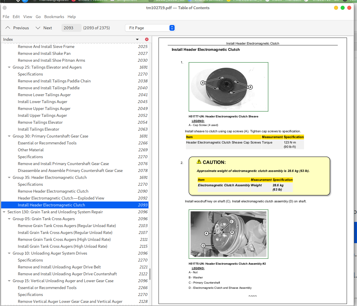
Install Header Electromagnetic Clutch................2093
Section 130: Grain Tank and Unloading System Repair................2096
Group 05: Grain Tank Cross Augers................2096
Remove Grain Tank Cross Augers (Regular Unload Rate)................2103
Install Grain Tank Cross Augers (Regular Unload Rate)................2107
Remove Grain Tank Cross Augers (High Unload Rate)................2111
Install Grain Tank Cross Augers (High Unload Rate)................2115
Group 10: Unloading Auger System Drives................2096
Specifications................2270
Remove and Install Unloading Auger Drive Belt................2121
Remove and Install Unloading Auger Drive Countershaft................2122
Group 15: Vertical Unloading Auger and Lower Gear Case................2096
Essential or Recommended Tools................2266
Specifications................2270
Remove Vertical Auger Lower Gear Case and Vertical Auger................2128
Disassemble and Assemble Vertical Auger Lower Gear Case-Regular Unload Rate................2132
Install Vertical Auger and Vertical Auger Lower Gear Case................2140
Group 20: Horizontal Unloading Auger and Gear Case................2096
Essential or Recommended Tools................2266
Other Material................2269
Specifications................2270
Inspection of Horizontal Unloading Auger................2149
Horizontal Unloading Auger—Regular Unload Rate................2150
Horizontal Unloading Auger—High Unload Rate................2152
Remove and Install Unloading Auger Grain Saver Door................2154
Remove Horizontal Auger................2155
Install Horizontal Auger................2157
Folding Horizontal Auger Tube—Exploded View................2160
Folding Horizontal Auger—Exploded View................2162
Folding Horizontal Auger Pivot—Exploded View................2164
Remove and Install Folding Auger Actuator................2166
Remove and Install Outer Folding Auger Assembly................2167
Remove and Install Folding Auger Rings................2169
Remove Rear Horizontal Folding Auger................2170
Remove Front Horizontal Folding Auger................2171
Install Front Horizontal Folding Auger................2173
Install Rear Horizontal Folding Auger................2176
Remove Horizontal Auger Gear Case................2177
Disassemble and Assemble Horizontal Unloading Auger Gear Case................2179
Install Horizontal Auger Gear Case................2184
Remove Horizontal Unloading Auger Tube................2185
Install Horizontal Unloading Auger Tube................2186
Unloading Auger Elbow—Exploded View................2187
Remove Horizontal Auger Elbow................2189
Install Horizontal Auger Elbow................2193
Remove Unloading Auger Charge Housing................2196
Install Unloading Auger Charge Housing................2200
Group 25: Clean Grain Elevator................2097
Other Material................2269
Specifications................2270
Adjust Clean Grain Elevator Chain................2206
Remove and Install Clean Grain Paddle Chain................2207
Remove and Install Clean Grain Paddle................2209
Remove Clean Grain Elevator................2210
Install Clean Grain Elevator................2218
Remove and Install Clean Grain Elevator Gear Case................2225
Disassemble and Assemble Clean Grain Elevator Gear Case................2227
Remove and Install Clean Grain Loading Auger Assembly................2234
Remove And Install Clean Grain Loading Auger................2237
Replace Clean Grain Loading Auger Bearing................2241
Remove and Install Lower Clean Grain Auger................2242
Group 30: Grain Tank and Covers................2097
Front and Rear Grain Tank Covers................2251
Side Grain Tank Covers................2253
Side Grain Tank Covers—HILLMASTER................2255
Grain Tank Cover Linkage................2257
Remove and Install Grain Tank Covers................2259
Section 140: Engine Gear Case and Control Valve Repair................2262
Group 05: Engine Gear Case and Valve................2262
Essential or Recommended Tools................2266
Other Material................2269
Specifications................2270
General Information................2272
Remove and Install Engine Gear Case................2273
Engine Gear Case Specifications................2284
Remove and Install Rotor Variable Drive................2286
Disassemble and Assemble Rotor Variable Drive................2289
Remove and Install Rotor Variable Drive Shaft................2299
Remove and Install Transfer Gear Case................2301
Disassemble and Assemble Transfer Gear Case................2306
Disassemble and Assemble Separator Drive Wet Clutch................2310
Disassemble and Assemble Hydrostatic Gear Set................2322
Set Gear Position................2324
Preload Bearings................2337
Disassemble and Assemble Straw Chopper/Unloading System................2330
Set Separator Gear Position................2335
Preload Bearings................2337
Disassemble and Assemble Separator Drive................2339
Preload Separator Drive Bearings................2342
Set Separator Drive Gear Backlash................2344
Disassemble and Assemble Hydrostatic Pump Drive................2345
Preload Hydrostatic Pump Drive Bearings................2347
Set Hydrostatic Pump Drive Gear Backlash................2348
Disassemble and Assemble Oil Screen................2349
Disassemble and Assemble Oil Trough................2350
Disassemble and Assemble Dipstick Tube................2352
Remove and Install Filter................2353
Remove and Install Pressure Regulating Valve................2354
Disassemble And Assemble Pressure Regulating Valve................2356
Section 199: Dealer Fabricated Tools................2363
Group 05: Dealer Fabricated Tools................2363
DFRW20—Compressor Holding Fixture................2365
DFHXT1—Split Ring Tool................2366
DFHXT2—Hydraulic Cylinder Tool................2367
DFHXT3—Swash Plate Holding Tool................2368
DFHXT4—Split Ring Tool................2370
DFHXT5—Shrink Ring Installation Tool................2371
John Deere S560 STS and S690 STS Combines Workshop Service Repair Manual - tm102719


