Mercedes-Benz W140 S-Class Factory Service & Workshop Manual 1991-1998
Catalog:
Model:
Complete workshop repair & service manual with electrical wiring diagrams for 1991-1998 Mercedes-Benz W140 S-Class. It's the same service manual used by dealers that guaranteed to be fully functional and intact without any missing page.
This 1991-1998 Mercedes-Benz W140 S-Class service & repair manual (including maintenance, overhaul, disassembling & assembling, adjustment, tune-up, operation, inspecting, diagnostic & troubleshooting…) is divided into different sections. Each section covers a specific component or system with detailed illustrations. A table of contents is placed at the beginning of each section. Pages are easily found by category, and each page is expandable for great detail. The printer-ready PDF documents work like a charm on all kinds of devices.
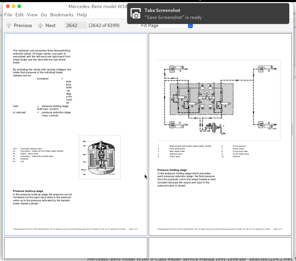
Mercedes-Benz model W140 S-Class Repair Service Manual 1991-1998.pdf
MAKE: Mercedes-Benz
YEAR: 1991 1992 1993 1994 1995 1996 1997 1998
MODEL:
300 SE / S 320 SWB / S 320 LWB
400 SE / 400 SEL / S 420
500 SEL / S 500
600 SEL / S 600
300 SD / S 350
500 SEC / S 500 Coupe
600 SEC / S 600 Coupe
CL 500
CL 600
TABLE OF CONTENTS (Exploded View)
!!! # Generated bmk file
00_Overall Vehicle................3
00.00 - 00 - Summary of test descriptions Diagnosis - Body Models 124, 129, 140, 163, 168, 170, 202, 208, 210 (dh0000pa0up00x)................11
00.00 - 00 - Survey of test descriptions Diagnosis Chassis Models 124, 129, 140, 170, 202, 210 (dh0000pf0up00x)................14
00.00 - 00 - Use of the diagnosis manual Diagnosis; Chassis - Body - Climate control - Information_Communication Models 124, 129, 140, 170, 201, 202, 210 (dh0000p00an00x)................15
00.00 - Assignment of data link connector (ad00.00-p-2000-02a)................17
00.00 - Assignment of data link connector (ad00.00-p-2000-02b)................18
00.00 - Assignment of data link connector (ad00.00-p-2000-02c)................19
00.00 - Connect STAR DIAGNOSIS and read out fault memory (ad00.00-p-2000-04a)................20
00.00 - Connect diagnosis testing equipment (ad00.00-p-2003a)................21
00.00 - Connect hand-held tester (HHT), read out diagnostic trouble code memory (ad00.00-p-2000-03c)................22
00.00 - Connecting Hand-Held Tester (HHT), reading out fault memory (ad00.00-p-2000-03a)................23
00.00 - Connecting Hand-Held Tester (HHT), reading out fault memory (ad00.00-p-2000-03b)................24
00.00 - Connecting and using test equipment (ad00.00-p-1000az)................25
00.00 - Diagnosis assignment (ad00.00-p-2002a)................26
00.00 - Diagnostic procedure (ad00.00-p-2004a)................27
00.00 - Disclaimer of liability for installation, removal, modification and body work documentation, form (of00.00-p-3000-10a)................28
00.00 - Explanation of diagnostic symbols (ad00.00-p-2001a)................29
00.00 - Explanation of symbols for testers and components (ad00.00-p-2000-01a)................30
00.00 - Form for queries about registration laws, manufacturer confirmations and technical data, form (of00.00-p-3000-09a)................31
00.00 - Notes on self-locking nuts and bolts (ah00.00-n-0001-01a)................32
00.00 - STAR DIAGNOSIS procedural schematic (ad00.00-p-2004-02a)................34
00.00 - Service Information Discontinuation of overviews of models and major assemblies (si00.00-z-0130a)................35
00.00 - Service Information Evaluation of high-voltage on-board electrical system after an accident, fire or complaints (si00.00-z-0151a)................37
00.00 - Service Information Evaluation of lithium-ion battery after an accident, fire or complaints (si00.00-z-0152a)................38
00.00 - Service Information Influence of vehicle systems on electronic medical devices (si00.00-p-0159a)................39
00.00 - Service Information New operation number structure for diagnosis jobs (si00.00-p-0051a)................40
00.00 - Service Information No liability for third-party retrofits (si00.00-p-0025a)................45
00.00 - Service Information Operation items for test drives (si00.00-p-0009a)................46
00.00 - Service Information Orientation values for ZM operation items for plausibility checks in warranty and goodwill cases (si00.00-p-0088a)................48
00.00 - Service Information QR code for rescue forces (si00.00-p-0089a)................51
00.00 - Service Information Qualification measures for working on high-voltage on-board electrical systems, lithium-ion batteries and gaseous fuel drive systems (si00.00-p-0156a)................52
00.00 - Service information Assessment of vehicles with high-voltage on-board electrical system and_or lithium-ion battery and_or gaseous-fuel drive system after accident, fire or problems (si00.00-z-0154a)................56
00.00 - Service information New update concept for diagnosis applications (si00.00-z-0004a)................57
00.00 - Service-Information Ausfu¨llen UPS-Absendeformular (si00.00-p-0085a)................58
00.00 - Service-Information Hinweise zum Ausfu¨llen des Altteile-Ru¨cklieferscheins (si00.00-p-0076a)................59
00.00 - Service-Information Unfallforschung (si00.00-p-0021a)................60
00.01 - Introduction of WIS Service Media (sn00.01-z-0012a)................61
00.01 - Service Information Content and application of data mediums Telematics CD_DVD, Regio DVD and Digital Owner‘s Manual DVD (si00.01-p-0014a)................63
00.01 - Service Information Damage or breakdown case in international traffic (si00.01-z-0031a)................64
00.01 - Service Information Invoicing of quick test (si00.01-p-0006a)................65
00.01 - Service Information SDconnect rechargeable battery (si00.01-p-0003a)................66
00.01 - Service Information Structure of the new operation numbers for SmallRepair in ASRA [operation texts, standard texts, flat rates and work units] (si00.01-z-0001a)................67
00.01 - Service Information Synonym search - New functionality in WIS (si00.01-z-0036a)................68
00.01 - Service Information Trouble diagnosis bulletins (AF) publication type not applicable (si00.01-z-0029a)................69
00.01 - Service Information Update of email distributor (si00.01-z-0037a)................70
00.01 - Service Information WIS Service Media (si00.01-z-0012a)................71
00.01 - Service Information bulletin on optimized design and location of system and function descriptions (si00.01-p-0009a)................72
00.01 - Service-Information Erreichbarkeit technische Werkstattbetreuung (si00.01-p-0023a)................73
00.01 - Service-Information Xentry Support & Feedback in WIS net (si00.01-z-0030a)................74
00.10 - Analysis sheet for engine noises, form (of00.10-p-3000-03a)................77
00.10 - Check gear capacity (ar00.10-p-1010a)................80
00.10 - Service Information Engine output increase (si00.10-p-0004a)................83
00.10 - Service Information Notes on safety-relevant components subject to redocumentation requirements (si00.10-p-0033a)................84
00.10 - Service Information Specified data for emissions inspection (si00.10-p-0037a)................86
00.10 - Service Information Vehicle identification plate orders (si00.10-p-0003b)................87
00.10 - Service-Information Dokumentation von Anziehdrehmomenten im WIS (si00.10-z-0013a)................88
00.10 - Service-Information Fahrzeug-Zulassungsdokumente (si00.10-p-0011a)................93
00.10 - Service-Information Prüfvorgaben für die Fahrzeuguntersuchung zur Vorbereitung der Hauptuntersuchung (HU) nach §29 StVZO (si00.10-p-0001a)................95
00.10 - Service-Information Umrüstung von Nicht-EU-Fahrzeugvarianten zur Zulassung in Deutschland (si00.10-p-0021a)................99
00.10 - Service-Information Änderungen bei der Abgasuntersuchung gem. AU-Geräteleitfaden Version 5.01 zum 01.01.2018 (si00.10-z-0034a)................100
00.19 - Connector part numbers (gf00.19-p-8100aa)................101
00.19 - Connector part numbers (gf00.19-p-8100ab)................102
00.19 - Connector part numbers (gf00.19-p-8100ag)................104
00.19 - Connector part numbers (gf00.19-p-8100an)................105
00.19 - General repair methods for wiring harness (ar00.19-p-0100a)................106
00.19 - Overall network (GVN), basic function (gf00.19-p-9900a)................110
00.19 - Plugs and couplings as-built configuration (gf00.19-p-8000a)................112
00.19 - Remove contacts from E 95 coupling (ar00.19-p-0120-05a)................114
00.19 - Remove contacts from Junior Power Timer coupling (ar00.19-p-0120-07a)................116
00.19 - Remove contacts from Multi Contact Point (MCP) coupling (ar00.19-p-0120-09a)................119
00.19 - Remove contacts from micro quadlock system coupling (ar00.19-p-0120-04a)................121
00.19 - Remove contacts from sensor laminated contact coupling (ar00.19-p-0120-02b)................124
00.19 - Removing contacts from plugs and connectors (ar00.19-p-0120a)................126
00.19 - Repair wiring harness as per specified repair method (ar00.19-p-0001a)................132
00.20 - 0006 - Overview, model, work sheet, order no. Models 107 from 8_85, 124_129_140 to 6_93, 126 from 9_85, 201 from 1_85, 123 (wh0000pkwvt06x)................134
00.20 - 0053 - Visual inspection for missing components, leakage assemblies, chafing points, line position Models; 107 from 08_85, 124, 126 from 09_85, 129, 140, 201 from 01_85 (wh0053pkw0000x)................135
00.20 - 0090 - Checking chassis and supporting body components for damage and corrosion Models 107 from 8_85, 124, 129, 140 to 6_93, 126 from 9_85, 201 from 1_85, 123 (wh0090pkw0000x)................147
00.20 - 1st care service 10000 - 12500 km, additional between the maintenance services every 10000 km_annually (ap00.20-p-1220a)................149
00.20 - Active service system (ASSYST) function description contents (gf00.20-p-0997az)................150
00.20 - Check all visible parts for leaks and damage (ap00.20-p-0053ba)................151
00.20 - Inspect chassis and load-bearing body parts for damage and corrosion (ap00.20-p-0090ba)................154
00.20 - Inspection service every 15000 km_annually (ap00.20-p-0013a)................157
00.20 - Maintenance (ap00.20-p-0000a)................159
00.20 - Maintenance (ap00.20-p-0000c)................160
00.20 - Maintenance (ap00.20-p-0000d)................161
00.20 - Maintenance service every 20 000 km_2 years (ap00.20-p-0005b)................162
00.20 - Maintenance service every 30 000 km_2 years (ap00.20-p-0014a)................166
00.20 - Overview of check before driving into working area (ap00.20-p-0062u)................170
00.20 - Overview of recurrent operations on vehicles in storage (ap00.20-p-0088a)................171
00.20 - SERVICE SHEET for Active Service System (ASSYST) (ap00.20-p-0001e)................172
00.20 - Service Information Adding AdBlue(R) during service (si00.20-p-0004a)................176
00.20 - Service Information Forms for delivery and hand-over inspections, inspections and checks in information type AP (si00.20-p-0044a)................178
00.40 - Automatic transmission fluids (ATF) (specification 236.14) (bb00.40-p-0236-14a)................179
00.40 - Automatic transmission fluids (ATF) (specification 236.6) (bb00.40-p-0236-06a)................180
00.40 - Automatic transmission fluids (ATF) (specification 236.7) (bb00.40-p-0236-07a)................181
00.40 - Directory of additional operating fluids (bb00.40-p-0300zz)................182
00.40 - General list (bb00.40-p-0000zz)................183
00.40 - Hydraulic fluids (Specification 345.0) (bb00.40-p-0345-00a)................184
00.40 - List of fuels (bb00.40-p-0100zz)................185
00.40 - List of lubricants (bb00.40-p-0200zz)................186
00.40 - Search aid for Specifications for Operating Fluids (bb00.40-p-0900a)................187
00.40 - Service Information Exclusive use of Mercedes-Benz lubricants in warranty and goodwill cases (si00.40-p-0009a)................192
00.40 - Service Information Specifications for Operating Fluids for anti-corrosion agents_antifreeze (si00.40-p-0019a)................193
00.40 - Service Information bulletin Specifications for Operating Fluids for automatic transmission (si00.40-p-0014a)................194
00.40 - Service information Dying of windshield washer fluid concentrate (si00.40-z-0006a)................196
00.40 - Specified gear oils (UNIMOG, MB-tractors) - overview (bb00.40-p-0231-03a)................197
00.40 - Specified gear oils (cars, cross-country vehicles) - survey (bb00.40-p-0231-01a)................198
00.40 - Specified transmission oils (commercial vehicle, van) - Overview (bb00.40-p-0231-02a)................201
00.40 - Wax preservation agents for underbody (bb00.40-p-0385-01a)................205
00.45 - Service Information Multipurpose metal grease (si00.45-p-0004a)................206
00.45 - Service Information Service kit for rectifying squeaking, creaking and tearing noises (si00.45-p-0002a)................207
00.60 - Raise_lower vehicle with vehicle lift (ar00.60-p-1006a)................208
00.60 - Raise_prop up vehicle with pit jack or vehicle jack (ar00.60-p-1003a)................210
01_Complete Engine, Crankcase Ventilation, Cylinder Head, Crankcase................211
01.00 - 0010 - Engine and model overview Engine 104 (ra01001040010x)................215
01.00 - 0085 - Warning instructions when hood open Engine 104 (ra01001040085x)................217
01.00 - Cleaning and preserving engine and engine compartment (ap01.00-p-1000zz)................218
01.00 - Combustion engine mechanical components, basic function (gf01.00-p-9900a)................219
01.00 - Combustion engine, basic function (gf01.00-p-9901a)................222
01.00 - Remove sealant (ar01.00-p-0050-01a)................223
01.00 - Technical modifications Passenger cars Complete engine, crankcase ventilation, cylinder head , crankcase (bt01.00-z-9999az)................224
01.00 - Test and adjustment values Passenger cars Complete engine, crankcase ventilation, cylinder head , crankcase (be01.00-z-9999az)................225
01.00 - Testing compression pressure (ar01.00-p-1200hw)................227
01.10 - 0015 - Checking cylinders for leaks Engines 601, 602 (except 602.98), 603 (ra01006010015x)................229
01.10 - 0020 - Illuminating the cylinder Engines 601, 602 (except 602.98), 603 (ra01006010020x)................235
01.10 - 0101 - Engine oil and filter change Models; 107 from 8_85, 124, 129, 140 to 6_93, 126 from 9_85, 201 from 1_85, 123 All engines (wh0101pkw0000x)................237
01.10 - 0150 - Testing cylinders for leaks Engine 119.96 KE, 119.97 LH, 119.98 ME (ra01001190150x)................251
01.10 - 0300 - B. Removing and installing engine Model 210 Engines 119.96 119.97, and 119.98 (ra0100119b300x)................253
01.10 - Remove_install engine (ar01.10-p-2400hx)................259
01.10 - Service Information Application of surface sealants (si01.10-p-0015a)................263
01.10 - Service Information Cleaning sealing surfaces (si01.10-p-0004a)................264
01.10 - Service Information Guidelines on engine number (si01.10-p-0014a)................265
01.10 - Service Information Note on mounting engine in assembly stand (si01.10-p-0016a)................266
01.10 - Service Information Standardized procedure for complaints on the engine (si01.10-p-0001a)................267
01.10 - Technical modifications Engine Removal_installation of engine, crankcase, cylinder head, crankcase ventilation Engines 601, 602 (except 602.98), 603 (ra0100601ta00x)................269
01.10 - Use of engine no. when installing reconditioned engines and factory-new replacement engines or crankcases (ah01.10-p-0001-01a)................270
01.20 - 0040 - Crankcase ventilation - Function A. Standard version, B.Naturally aspirated and turbo-engines with exhaust gas re-circulation, Engines 601, 602 (except 602.98), 603 (ra01006010040x)................271
01.20 - 0400 - Function description of the crankcase ventilation Engines 104.98 KE-Jetronic, 104.990 LH-Jetronic, 104.941-5_991-2_994-6 (HFM) Engine 104 (ra01001040400x)................278
01.30 - 0400 - Repair notes for the cylinder heads and gaskets A. Engine 601, B. Engines 602 (except 602.98), 603 (ra01006010400x)................283
01.30 - 0410 - Refinishing the precombustion chamber sealing surface Engines 601, 602 (except 602.98), 603 (ra01006010410x)................291
01.30 - 0416 - Modifications to the precombustion chambers Engines 601, 602 (except 602.98), 603 (ra01006010416x)................297
01.30 - 0417 - Removal and installation of the precombustion chambers Engines 601, 602 (except 602.98), 603 (ra01006010417x)................304
01.30 - 0418 - Facing cylinder head contact face Engines 601, 602 (except 602.98), 603 (ra01006010418x)................312
01.30 - 0420 - Pressure test of the cylinder head Engines 601, 602 (except 602.98), 603 (ra01006010420x)................316
01.30 - 0500 - C. Removing and installing cylinder head cover Engines with HFM-SFI fuel injection Engine 104 (ra0100104c500x)................318
01.30 - 4070 - Repair of the spark plug threads Engine 104 (ra01001044070x)................320
01.30 - 4150 - Removal and installation of the cylinder head A. Models 124, 140, 210, B. Model 129 Engine 119.960 (ra01001194150x)................323
01.30 - Remove_install cylinder head (ar01.30-p-5800hx)................340
01.40 - 0130 - Knocking out and inserting the steel balls in the main oil duct Engines 601, 602 (except 602.98), 603 (ra01006010130x)................344
01.40 - 0140 - Replacement of the core hole plug caps in the crankcase Engines 601, 602 (except 602.98), 603 (ra01006010140x)................347
01.40 - 0211 - Modifications to the timing case cover Engines 601, 602 (except 602.98), 603 (ra01006010211x)................350
01.40 - 0222 - Removal and installation of the end cap Engines 601, 602 (except 602.98), 603 (ra01006010222x)................353
01.40 - 1000 - Notes regarding the crankcase Engine 104 (ra01001041000x)................357
01.40 - 1200 - Facing crankcase mating surface Engine 119.96 KE, 119.97 LH, 119.98 ME (ra01001191200x)................359
01.40 - 1220 - Repair of the threaded bores for the cylinder head bolts Engine 104 (ra01001041220x)................361
01.40 - 2100 - Removal and installation of the timing case cover A. Engine 119.960 KE, B. Engine 119.97_98 LH_ME (ra01001192100x)................363
01.40 - Boring and honing cylinder bores (ar01.40-p-9291aw)................379
01.40 - Installing cylinder liner (ar01.40-p-9273aw)................381
01.40 - Machining the crankcase contact surface (ar01.40-p-9133aw)................382
01.40 - Measuring cylinder bores (ar01.40-p-9202aw)................385
01.40 - Remove cylinder liner (ar01.40-p-9272aw)................387
01.40 - Remove_install timing case cover (ar01.40-p-8000hx)................389
01.40 - Widening cylinder bore in crankcase (ar01.40-p-9271aw)................392
01.45 - 0315 - Design differences and modifications to oil pans Engines 601, 602 (except 602.98), 603 (ra01006010315x)................394
01.45 - Remove_install oil pan (ar01.45-p-7500hy)................400
03_Crank Assembly................403
03.00 - 0345 - Checking and correcting adjustment of TDC sensor Engines 601, 602 (except 602.98), 603 (ra03006010345x)................405
03.00 - Prüf- und Einstellwerte Personenwagen Triebwerk (be03.00-z-9999az)................411
03.00 - Technical modifications Crank assembly Engines 601, 602 (except 602.98), 603 (ra0300601ta02x)................414
03.00 - Technical modifications Passenger cars Crank assembly (bt03.00-z-9999az)................415
03.10 - 0317 - Modifications to the pistons Engines 601, 602 (except 602.98), 603 (ra03006010317x)................416
03.10 - 3170 - Replacement of piston rings Engine 119 (ra03001193170x)................423
03.10 - Check_repair connecting rod (ar03.10-p-6111aw)................425
03.10 - Removing _ installing a piston (ar03.10-p-7021aw)................430
03.20 - 0318 - Checking and reconditioning the crankshaft Engines 601, 602 (except 602.98), 603 (ra03006010318x)................435
03.20 - 0321 - Modifications to the crankshaft Engines 601, 602 (except 602.98), 603 (ra03006010321x)................444
03.20 - 0327 - Replacement of the rear crankshaft radial sealing ring Engines 601, 602 (except 602.98), 603 (ra03006010327x)................449
03.20 - 0330 - Removal and installation of radial ball bearing in crankshaft Engines 601, 602 (except 602.98), 603 (ra03006010330x)................453
03.20 - 0350 - Removal and installation of the crankshaft sprocket Engines 601, 602 (except 602.98), 603 (ra03006010350x)................456
03.20 - 0500 - Installing, removing retaining lock for crankshaft_ring gear Engines 601, 602 (except 602.98), 603 (ra03006010500x)................461
03.20 - 1800 - Removal and installation of the crankshaft Engine 104 (ra03001041800x)................464
03.20 - 3190 - Crankshaft machining dimensions and identifications Engine 104 (ra03001043190x)................467
03.20 - Measure crankshaft and remount in bearings (ar03.20-p-4355aw)................469
03.20 - Replacing front crankshaft radial seal (ar03.20-p-3000hw)................473
03.30 - 0420 - Refinishing flywheel Engines 601, 602 (except 602.98), 603 (ra03006010420x)................474
03.30 - 0430 - Replacement of the flywheel ring gear Engines 601, 602 (except 602.98), 603 (ra03006010430x)................476
03.30 - 3450 - Checking and correction of the TDC-sensor setting Engine 104 (ra03001043450x)................478
03.30 - 4100 - Removal and installation of the driven plate with ring gear Engine 104 (ra03001044100x)................482
03.30 - 4300 - Replacement of the ring gear Engine 119 (ra03001194300x)................485
03.30 - Remove_install flywheel _ drive plate (ar03.30-p-8001hw)................487
03.30 - Removing and installing belt pulley_vibration damper (ar03.30-p-1600hw)................490
05_Engine Timing................492
05.00 - Checking hydraulic valve clearance compensating elements (ar05.00-p-2010hw)................494
05.00 - Engine management, basic function (gf05.00-p-9901a)................495
05.00 - Removing, installing hydraulic valve clearance compensation elements (bucket tappets) (ar05.00-p-2011hx)................497
05.00 - Technical modifications Passenger cars Engine timing (bt05.00-z-9999az)................498
05.00 - Test and adjustment values Passenger cars Engine timing (be05.00-z-9999az)................499
05.10 - 0310 - Removal and installation of the chain tensioner Engines 601, 602 (except 602.98), 603 (ra05006010310x)................501
05.10 - 0330 - Removal and installation of the tensioner rail Engines 601, 602 (except 602.98), 603 (ra05006010330x)................504
05.10 - 0341 - Removal and installation of the guiding rails A. In cylinder head, B. In timing case Engines 601, 602 (except 602.98), 603 (ra05006010341x)................506
05.10 - 0437 - Removal and installation of the pressure oil pump drive Engines 601, 602 (except 602.98), 603 (ra05006010437x)................511
05.10 - 3200 - Replacement of and riveting the timing chain Engine 119 (ra05001193200x)................513
05.10 - Replacing timing chain (ar05.10-p-7601hx)................517
05.20 - 0220 - Removal and installation of the camshaft Engines 601, 602 (except 602.98), 603 (ra05006010220x)................519
05.20 - 2240 - Adjustment of the basic position of the camshafts Engine 104 (ra05001042240x)................528
05.20 - Checking basic position of camshafts (ar05.20-p-6010hw)................530
05.20 - Checking camshaft timing (ar05.20-p-6015hw)................531
05.30 - 0260 - Checking the valve springs Engines 601, 602 (except 602.98), 603 (ra05006010260x)................533
05.30 - 0285 - Checking and replacement of the valve guides Engines 601, 602 (except 602.98), 603 (ra05006010285x)................535
05.30 - 0290 - Replacement of the valve seat rings Engines 601, 602 (except 602.98), 603 (ra05006010290x)................541
05.30 - 0291 - Machining the valve seats Engines 601, 602 (except 602.98), 603 (ra05006010291x)................546
05.30 - 2600 - Inspecting valve springs Engine 119 (ra05001192600x)................550
05.30 - 2845 - Checking the valve guides Engine 104 (ra05001042845x)................552
05.30 - 2850 - Replacement of the valve guides Engine 119 (ra05001192850x)................553
05.30 - Checking and machining valves (ar05.30-p-4201hw)................567
05.30 - Removing and installing valve springs and_or valve stem seals (ar05.30-p-3500hx)................570
05.30 - Technical modifications Engine timing, valves Engines 601, 602 (except 602.98), 603 (ra0500601ta03x)................572
07_Mixture Formation................573
07.00 - 0002 - List of models and components Engines 602.96, 603.96_97 TURBO (ra07016020002x)................583
07.00 - C - Diagnostic Testers 21 - Fault code with diagnostic testers All Engines (dh0c00pm10021x)................586
07.00 - C - Diagnostic Testers 31 - Connection diagram All Engines (dh0c00pm10031x)................589
07.00 - C - Diagnostic Testers 48 - Diagnostic test All Engines (dh0c00pm00048x)................590
07.00 - Check and adjust engine (ar07.00-p-3001wa)................618
07.00 - Check and adjust engine (ar07.00-p-3001wb)................621
07.00 - D - Diagnosis Paths 11_1 - Complaint - Starting behavior_Starting time All Engines (dh0d00pm11101x)................624
07.00 - D - Diagnosis Paths 11_2 - Complaint - Idling not smooth, surging_misfiring All Engines (dh0d00pm11102x)................625
07.00 - Engine test and setting operations (ar07.00-p-3000wa)................626
07.00 - Engine test and setting operations (ar07.00-p-3000wb)................627
07.00 - Engine test and setting operations (ar07.00-p-3000wc)................628
07.00 - Exhaust emission test I (ar07.00-p-1000a)................629
07.00 - Extension to testing, adjusting engine (ar07.00-p-3004wa)................630
07.00 - Extension to testing, adjusting engine (ar07.00-p-3004wb)................631
07.00 - Extension to testing, adjusting engine (ar07.00-p-3004wc)................632
07.00 - Information sheet on engine performance tuning, certificate (of07.00-p-1000-04a)................633
07.00 - Notes on actual value screens (ah07.00-p-3000-02wa)................634
07.00 - Service Information Fuel consumption measurement (si07.00-p-0004a)................635
07.00 - Service Information Return delivery of diagnostic data (si07.00-p-0010a)................637
07.00 - Service-Information Daten zur Abgasuntersuchung (AU-Solldaten) (si07.00-z-0011a)................638
07.00 - Technical modifications Passenger cars Mixture formation (bt07.00-z-9999az)................639
07.00 - Test and adjustment values Passenger cars Mixture formation (be07.00-z-9999az)................640
07.00 - Test engine performance and exhaust emissions (ar07.00-p-3003wa)................642
07.00 - Test engine performance and exhaust emissions (ar07.00-p-3003wb)................645
07.00 - Test sheet for fuel consumption measuring drive, form (of07.00-p-3000-01a)................648
07.00 - Test, regulate idle speed (ar07.00-p-3002wa)................650
07.00 - Test, regulate idle speed (ar07.00-p-3002wb)................652
07.02 - Adjust start of delivery using digital test equipment (after check) (ap07.02-p-0761ha)................654
07.02 - Check start of delivery with digital test equipment (ap07.02-p-0760ha)................655
07.08 - Combustion engine control unit, basic function (gf07.08-p-9890a)................657
07.10 - Heat management, basic function (gf07.10-p-9900a)................658
07.11 - 0010 - Function of injection system U. Electronic diesel system (EDS) A. General Engines 602.96, 603.96_97 Turbo (ra07216020a10x)................659
07.11 - 0010 - Function of injection system U. Electronic diesel system (EDS) B. Location of components Engines 602.96, 603.96_97 Turbo (ra07216020b10x)................660
07.11 - 0010 - Function of injection system U. Electronic diesel system (EDS) C. Function diagrams Engines 602.96, 603.96_97 Turbo (ra07216020c10x)................670
07.11 - 0010 - Function of injection system U. Electronic diesel system (EDS) D. Influencing variables of EDS Engines 602.96, 603.96_97 Turbo (ra07216020d10x)................680
07.11 - 0010 - Function of injection system U. Electronic diesel system (EDS) E. ELR Engines 602.96, 603.96_97 Turbo (ra07216020e10x)................687
07.11 - 0010 - Function of injection system U. Electronic diesel system (EDS) F. Exhaust gas recirculation (ARF) Engines 602.96, 603.96_97 Turbo (ra07216020f10x)................689
07.11 - 0010 - Function of injection system U. Electronic diesel system (EDS) G. Recirculting air control Engines 602.96, 603.96_97 Turbo (ra07216020g10x)................691
07.11 - 0010 - Function of injection system U. Electronic diesel system (EDS) H. Charge pressure control (P2 control) Engines 602.96, 603.96_97 Turbo (ra07216020h10x)................693
07.11 - 0010 - Function of injection system U. Electronic diesel system (EDS) I. System diagnostics Engines 602.96, 603.96_97 Turbo (ra07216020i10x)................697
07.11 - 0010 - Function of injection system U. Electronic diesel system (EDS) J. Location and function of components Engines 602.96, 603.96_97 Turbo (ra07216020j10x)................698
07.11 - 0010 - Function of the injection system B. Fuel circuit Engines 602.96, 603.96_97 TURBO (ra07026020010x)................719
07.11 - 0010 - Function of the injection system C. Fuel prefilter (43) Engines 602.96, 603.96_97 TURBO (Model 463.3 pay attention to deviations) (ra07036020010x)................722
07.11 - 0010 - Function of the injection system D. Fuel filter (42) Engines 602.96, 603.96_97 TURBO (Model 463.3 pay attention to deviations) (ra07046020010x)................723
07.11 - 0010 - Function of the injection system E. Fuel preheater (148) Engines 602.96, 603.96_97 TURBO (Model 463.3 pay attention to deviations) (ra07056020010x)................724
07.11 - 0010 - Function of the injection system F. Fuel pump (3) Engines 602.96, 603.96_97 TURBO (Model 463.3 pay attention to deviations) (ra07066020010x)................725
07.11 - 0010 - Function of the injection system G.Start of delivery adjusting device Engines 602.96, 603.96_97 TURBO (Model 463.3 pay attention to deviations) (ra07076020010x)................727
07.11 - 0010 - Function of the injection system H. Reverse flow damping valve in delivery valve holder - Engines 602.96, 603.96_97 TURBO (Model 463.3 pay attention to deviations) (ra07086020010x)................728
07.11 - 0010 - Function of the injection system I. Injection timer Engines 602.96, 603.96_97 TURBO (Model 463.3 pay attention to deviations) (ra07096020010x)................729
07.11 - 0010 - Function of the injection system J. RSF governor Engine 602.96, 603.96_97 TURBO (Model 463.3 pay attention to variations) (ra07106020010x)................730
07.11 - 0010 - Function of the injection system K. Intake manifold pressure compensator (ALDA) - Engine 602.96, 603.96_97 TURBO (Model 463.3 pay attention to variations) (ra07116020010x)................735
07.11 - 0010 - Function of the injection system L. Control rod travel sensor (L7) Engine 602.96, 603.96_97 TURBO (Model 463.3 pay attention to variations) (ra07126020010x)................737
07.11 - 0010 - Function of the injection system M.Reference impulse verification (RIV) Engine 602.96, 603.96_97 TURBO - (Model 463.3 pay attention to varations) (ra07136020010x)................738
07.11 - 0010 - Function of the injection system N. Electronic idle speed control(ELR) Engine 602.96, 603.96_97 TURBO (Model 463.3 pay attention to variations) (ra07146020010x)................739
07.11 - 0010 - Function of the injection system P. Facet pintle nozzle Engine 602.96, 603.96_97 TURBO (Model 463.3 pay attention to variations) (ra07166020010x)................743
07.11 - 0010 - Function of the injection system Q. Nozzle holder Engine 602.96, 603.96_97 TURBO (Model 463.3 pay attention to variations) (ra07176020010x)................744
07.11 - 0010 - Function of the injection system R. Oblique injection Engine 602.96, 603.96_97 TURBO (Model 463.3 pay attention to variations) (ra07186020010x)................746
07.11 - 0010 - Function of the injection system S. Injection lines Engine 602.96, 603.96_97 TURBO (Model 463.3 pay attention to variations) (ra07196020010x)................747
07.11 - 0010 - Function of the injection system T. Vacuum engine stop with car key (glow-start switch) - Engine 602.96, 603.96_97 TURBO (Model 463.3 pay attention to deviations) (ra07206020010x)................748
07.11 - 0010 - Function of the injection system V. Engine overload protection Engine 602.96, 603.96_97 TURBO (Model 463.3 pay attention to deviations) (ra07226020010x)................751
07.11 - 0010 - Function of the injection system W. Handling electronic control units after accident repair Engine 602.96, 603.96_97 TURBO (Model 463.3 pay attention to deviations) (ra07236020010x)................754
07.11 - 0195 - A. Testing exhaust gas recirculation Engines 601.911_912 up to 01_93, 602, 603 (ra0701601a195x)................755
07.11 - 0500 - Vacuum diagrams 17 - Engine 603 (A),(CH),(S) Model year 1989 Vacuum circuit diagram, Exhaust gas recirculation with manual transmission (ra0701601q500x)................769
07.11 - 0500 - Vacuum diagrams 18 - Engine 603 (A),(CH),(S) and Code 830 Model year 1989 Vacuum circuit diagram, Exhaust gas recirculation with automatic transmission (ra0701601r500x)................770
07.11 - 1842 - Testing vacuum engine stop for leaks Engine 603.97 Turbo in Model 140 (ra07b16021842x)................771
07.12 - 0001 - Additional designations for models and components Engines 602.96, 603.96_97 TURBO (ra07016020001x)................773
07.12 - 0004 - Vehicle features Engines 602.96, 603.96_97 TURBO (ra07016020004x)................775
07.12 - 0007 - Key to code of injection pump type plate A. Key to code, B. Location of components on injection pump Engines 602.96, 603.96_97 TURBO (ra07016020007x)................790
07.12 - 0010 - Function of the injection system A. Lubrication of injection pump Engines 602.96, 603.96_97 TURBO (ra07016020010x)................792
07.12 - 0500 - Y. Vacuum Circuit Diagrams Engine 603.971 with A_T in Model 140 (USA) Model Year 1992 (ra0701602y500x)................793
07.12 - 1100 - Testing and adjustment of the engine Engines 602.96, 603.96_97 TURBO (ra07016021100x)................795
07.12 - 1203 - Testing the engine output and exhaust on the roller dynamometer Engines 602.96, 603.96_97 TURBO (ra07016021203x)................802
07.12 - 1333 - Determination of the fuel consumption by a road test Engines 602.96, 603.96_97 TURBO (ra07016021333x)................814
07.12 - 1826 - Testing and setting the vacuum control valve Engines 602.96, 603.96_97 TURBO (ra07016021826x)................815
07.12 - 1855 - Replacement of the electronic idle speed control (ELR) Engines 602.96, 603.96_97 TURBO in Models 124, 126, 140, 201 (ra07016021855x)................818
07.12 - 1856 - Replacement of the anti-jerk control (ARA) Engines 602.96, 603.96_97 TURBO in Models 124, 126, 140, 201 (ra07016021856x)................819
07.12 - 2053 - Checking and adjustment of the idling speed Engines 602.96, 603.96_97 TURBO in Models 124, 126, 140, 201 (ra07016022053x)................821
07.12 - 6712 - Testing the injection nozzles Engines 602.96, 603.96_97 TURBO in Models 124, 126, 140, 201 (ra07016026712x)................826
07.12 - 6750 - Adjustment of the injection nozzles (after testing) Engines 602.96, 603.96_97 TURBO in Models 124, 126, 140, 201 (ra07016026750x)................827
07.12 - 6810 - Removal and installation of the injection nozzle Engines 602.96, 603.96_97 TURBO in Models 124, 126, 140, 201 (ra07016026810x)................830
07.12 - 8050 - Servicing the timing device Engines 602.96, 603.96_97 TURBO in Models 124, 126, 140, 201 (ra07016028050x)................832
07.12 - 8240 - Testing start of delivery using the position sensor Engines 602.96, 603.96_97 TURBO in Models 124, 126, 140, 201 (ra07016028240x)................833
07.12 - 8244 - Testing start of delivery using the digital tester (RIV method) Engines 602.96, 603.96_97 TURBO in Models 124, 126, 140, 201 (ra07016028244x)................836
07.12 - 8300 - Adjustment of the start of delivery following test A. Using position sensor (RIV method), B. Using digital tester (RIV method) Engines 602.96, 603.96_97 TURBO - in Models 124, 126, 140, 201 (ra07016028300x)................841
07.12 - 8410 - Removal and installation of the injection pump Engines 602.96, 603.96_97 TURBO in Models 124, 126, 140, 201 (ra07016028410x)................847
07.12 - 8618 - Replacement of the vacuum unit Engines 602.96, 603.96_97 TURBO in Models 124, 126, 140, 201 (ra07016028618x)................854
07.12 - 8627 - Replacement of the pressure valve seal Engines 602.96, 603.96_97 TURBO in Models 124, 126, 140, 201 (ra07016028627x)................855
07.12 - 8823 - Removal and Installation of DSV Control Module Engine 603.971 in Model 140 (ra07016028823x)................856
07.12 - Technical modifications Diesel Injection system Engines 602.96, 603.96_97 TURBO (ra0701602ta01x)................860
07.14 - 8014 - Removal and installation of the injection timer Engines 602.96, 603.96_97 TURBO in Models 124, 126, 140, 201 (ra07016028014x)................864
07.32 - 0750 - Checking and adjustment of the idle speed, emission value_lambda control Engines 104, 119, 120 LH-injection (except USA) Models 124, 129, 140 to 6_93 (wh0750pkw0040z)................870
07.32 - 0750 - Leerlauf, Abgaswert_Lambda-Regelung prüfen, nachregulieren Motor 104, 119, 120 LH-Einspritzanlage (gilt nicht für USA) Typen 124, 129, 140 bis 6_93; (wh0750pkw0040x)................876
07.41 - B2 - Test and Adjustment Operations 41 - Testing, adjusting idle speed Engine 104, 119, 120 LH (dh0b02pm10041x)................881
07.51 - 0004 - Function description Vehicle features HFM_PMS-injection (ra0705hfm0004x)................886
07.51 - 0020 - Function description Influencing parameters at the control unit A. Engine 104 HFM, B. Engine 111 HFM, C. Engine 111 PMS HFM_PMS-injection (ra0705hfm0020x)................888
07.51 - 0030 - Function description HFM design and function A. General, B. Fuel supply, C. Functions in HFM control unit, D. Mixture formation, E. Influencing parameters for control (ra0705hfm0030x)................894
07.61 - 9.5 - Fuel injection and ignition system (ME-SFI1.0) 11 - Diagnosis - Fault memory Engine 119 ME (dh0905pm00011x)................932
07.61 - 9.5 - Fuel injection and ignition system (ME-SFI1.0) 23 - Test program - Electrical system, Testing fuel injection system Engine 119 ME (dh0905pm00023x)................939
07.61 - 9.5 - Fuel injection and ignition system (ME1.0) 12 - Diagnsois - Troubleshooting chart Engine 119 (dh0905pm00012x)................950
07.61 - 9.5 - Fuel injection and ignition system (ME1.0) 13 - Diagnosis - Fault code description Engine 119 ME (dh0905pm00013x)................952
07.61 - 9.5 - Fuel injection and ignition system (ME1.0) 21 - Test program - Electrical system, Location of components Engine 119 ME (dh0905pm00021x)................962
07.61 - 9.5 - Fuel injection and ignition system (ME1.0) 22 - Test program - Electrical system, Prerequisites for testing Engine 119 ME (dh0905pm00022x)................969
07.61 - 9.5 - Fuel injection and ignition system (ME1.0) 24 - Test program - Electrical system, Testing ignition system Engine 119 (dh0905pm00024x)................972
07.61 - 9.5 - Fuel injection and ignition system (ME1.0) 25 - Test program - Electrical system, Testing electronic accelerator Engine 119 (dh0905pm00025x)................978
07.61 - 9.5 - Fuel injection and ignition system (ME1.0) 26 - Test program - Electrical system, Testing cruise control Engine 119 (dh0905pm00026x)................980
07.61 - B1 - Test and adjustment work 23 - checking and adjusting engine Engine 111,119,120 ME (dh0b01pm00023x)................981
07.61 - Fuel injection and ignition system (ME-SFI) diagnosis contents (ad07.61-p-1000wz)................984
07.61 - ME-SFI fuel injection and ignition system model and component installation survey as-built configuration (gf07.61-p-0801f)................985
07.61 - Motor electronics (ME-SFI) fuel injection and ignition system contents function description (gf07.61-p-0999z)................986
07.61 - Motor electronics (ME-SFI) fuel injection and ignition system survey of system components location_task_design_function (gf07.61-p-9999f)................990
07.61 - Pneumatic diagrams ME-SFI (pp07.61-p-5000e)................993
07.61 - Pneumatic diagrams ME-SFI (pp07.61-p-5000eu)................994
07.61 - Test_adjust idle speed, emission value_lambda control (ME-SFI) (ap07.61-p-0750a)................995
08_Electric Drive, Hybrid Drive................998
08.00 - Alternative drives, basic function (gf08.00-p-9900a)................999
08.00 - Electric drive, basic function (gf08.00-p-9901a)................1000
08.00 - Test and adjustment values Passenger cars Electrical drive system (be08.00-z-9999az)................1001
08.20 - Electric drive powertrain control unit, basic function (gf08.20-p-9892a)................1002
08.20 - Electric drive sound generator, basic function (gf08.20-p-9890a)................1003
08.20 - Power electronics control unit, basic function (gf08.20-p-9891a)................1005
08.30 - Hybrid system, basic function (gf08.30-p-9900a)................1006
09_Air Intake, Turbocharging................1008
09.00 - 0200 - Function of engine overload protection (not for engines with P2 control) Engines 602.96, 603.96_97 TURBO in Models 124, 126, 140, 201 (Model 463.3 for deviations see introductory notes) (ra09006020200x)................1010
09.00 - 5921 - Testing engine overload protection (not for engines with P2 control) Engines 602.96, 603.96_97 TURBO (Model 463.3 for deviations see introductory notes) (ra09006025921x)................1012
09.00 - Charging, basic function (gf09.00-p-9900a)................1014
09.00 - Technical modifications Passenger cars Air intake, supercharging (bt09.00-z-9999az)................1016
09.00 - Test and adjustment values Passenger cars Air intake, supercharging (be09.00-z-9999az)................1017
09.10 - 0932 - Cleaning the air cleaner element, with perforated plate All engines - Only in countries with high dust deposits Models 107 from 8_85, 123, 124, 126 from 9_85, 129, 140 to 6_93, 201 from 1_85 (wh0932pkw0000x)................1018
09.10 - 0980 - Replacement of the air cleaner element All engines except 116, 117 with air pump Models 107 from 8_85, 123, 124, 126 from 9_85, 129, 140 to 6_93, 201 from 1_85 (wh0980pkw0000x)................1019
09.10 - 1051 - Removal and Installation of Air Cleaner C. Engine 603.97 in Model 140 (ra090c6021051x)................1020
09.10 - Air intake air intake hose version (gf09.10-p-0001-01a)................1021
09.10 - Luftfilter aus-, einbauen (ar09.10-p-1050e)................1022
09.10 - Removing and installing intake scoop (ar09.10-p-8221fb)................1023
09.20 - Manifold vacuum assist (MVA) arrangement of pneumatic components (gf09.20-p-0001-02a)................1024
09.40 - 0050 - Function of exhaust gas turbocharger Engines 602.96, 603.96, 603.971 TURBO in Models 124, 126, 140, 201 (model 463.3 for deviations see introductory notes) (ra09006020050x)................1025
09.40 - 5911 - Testing the exhaust gas turbocharger - Engines 602.96, 603.96_97 TURBO Engines; A. With overload protection, B. Without overload protection (Model 463.3 for deviations see introductory notes) (ra09006025911x)................1036
09.40 - 6020 - Removal and installation of the exhaust gas turbocharger Engines 602.96, 603.96_97 TURBO (Model 463.3 for deviations see introductory notes) (ra09006026020x)................1040
13_Air Compressor, Belt Drives................1045
13.00 - Technical modifications Passenger cars Air compressor, belt drives (bt13.00-z-9999az)................1046
13.00 - Test and adjustment values Passenger cars Air compressor, belt drives (be13.00-z-9999az)................1047
13.20 - 0343 - Checking condition of poly V-belt and tensioner A. Poly V-belt, B. Tensioner Engines 601, 602 (except 602.98), 603 (ra13006010343x)................1048
13.20 - 1351 - Poly V-belts - Check condition All engines (single-belt drive) Models 107 from 8_85, 124, 126 from 9_85, 129, 140 to 6_93, 201 from 1_85 (wh1351pkw0000x)................1055
13.20 - 3440 - Poly V-belts, running diagrams, dimensions Engine 119 (ra13001193440x)................1065
13.20 - Technical modifications Belt drive Engines 601, 602 (except 602.98), 603 (ra1300601ta03x)................1069
13.22 - Check visible area of poly-V belt for wear (ap13.22-p-1352z)................1070
13.22 - Remove_install poly-V belt (ar13.22-p-1202hw)................1071
13.25 - Remove_install poly-V belt tensioning device (ar13.25-p-3200hw)................1073
14_Exhaust Manifold, Engine Brake, Emission Control System................1075
14.00 - 0020 - Function of the emission control system Engines 602.96, 603.96_97 TURBO (Model 463.3 for deviations see introductory notes) (ra14006020020x)................1076
14.00 - 0150 - Testing the exhaust back pressure (USA) Engines 602.96, 603.96_97 TURBO (Model 463.3 for deviations see introductory notes) (ra14006020150x)................1077
14.00 - Technical modifications Passenger cars Exhaust manifold, engine brake, emission control system (bt14.00-z-9999az)................1080
14.00 - Technical modifications Trap oxidizer, charge air pipe, exhaust manifold Engines 602.96, 603.96_97 TURBO (Model 463.3 for deviations see introductory notes) (ra1400602ta04x)................1081
14.00 - Test and adjustment values Passenger cars Exhaust manifold, engine brake, emission control system (be14.00-z-9999az)................1083
14.10 - 3900 - Removal and installation of the exhaust manifold Engines 602.96, 603.96_97 TURBO (Model 463.3 for deviations see introductory notes) (ra14006023900x)................1084
14.30 - 1310 - Removal and installation of the charge air pipe Engines 602.96, 603.96_97 TURBO Model 463.3 for deviations see introductory notes) (ra14006021310x)................1085
14.30 - Remove_install air pump (ar14.30-p-7251ea)................1087
14.40 - 0050 - Function of the trap oxidizer (USA) Engines 602.96, 603.96_97 TURBO (Model 463.3 for deviations see introductory notes) (ra14006020050x)................1088
14.40 - 0100 - Removal and installation of the trap oxidizer (USA) Engines 602.96, 603.96_97 TURBO (Model 463.3 for deviations see introductory notes) (ra14006020100x)................1090
14.40 - Service Information Fill AdBlue container (si14.40-p-0014a)................1092
14.40 - Service Information Return delivery of AdBlue tank (si14.40-p-0023a)................1093
15_Electrical System - Engine................1094
15.00 - 0010 - Function description Notes regarding working on breakerless ignition system LH Injection System (ra1500flh0010x)................1097
15.00 - Check spark plugs and replace if necessary (ap15.00-p-1550z)................1100
15.00 - Technical modifications Passenger cars Electrical system - engine (bt15.00-z-9999az)................1101
15.00 - Test and adjustment values Passenger cars Electrical system - engine (be15.00-z-9999az)................1102
15.10 - 1550 - Checking and replacement of the spark plugs All gasoline engines (USA and Taiwan only) Models 107 from 8_85, 123, 124, 126 from 9_85, 129, 140 to 6_93, 201 from 1_85 (wh1550pkw0000x)................1103
15.10 - 1554 - Checking and adjustment of the ignition timing All gasoline engines from 1981 to 1983 (AUS_J_CH_S) Models 107 from 8_85, 123, 124, 126 from 9_85, 129, 140 to 6_93, 201 from 1_85 (wh1554pkw0000x)................1104
15.10 - 1580 - Replacement of the spark plugs Gasoline engines Models 107 from 8_85, 123, 124, 126 from 9_85, 129, 140 to 6_93, 201 from 1_85 (wh1580pkw0000x)................1106
15.10 - General notes on testing contactless high voltage distribution (ah15.10-p-1003-01w)................1109
15.10 - Replace spark plugs (ap15.10-p-1580ea)................1111
15.10 - Service Information Spark plug connector grease (si15.10-p-0004a)................1114
15.10 - Technical modifications Electrical system, engine (ignition system) Model 140 (ra1500140ta00x)................1115
15.10 - Test rotorless high voltage distribution (ar15.10-p-3000wa)................1116
15.10 - Test rotorless high voltage distribution (ar15.10-p-3000wd)................1117
15.10 - Test rotorless high voltage distribution (ar15.10-p-3000we)................1118
15.18 - Servicing wiring harness (ar15.18-p-0500a)................1119
15.20 - 0705 - Function of Preglow System Engine 602.96, 603.96_97 TURBO (Model 463.3 for deviations see introductory notes) (ra15006020705x)................1120
15.20 - 4000 - Testing the pre glow system - A. Without after glow, B. With after glow Engines 602.96, 603.96_97 TURBO (Model 463.3 for deviations see introductory notes) (ra15006024000x)................1132
15.20 - 4111 - Removal and installation of the glow plugs Engines 602.96, 603.96_97 TURBO (Model 463.3 for deviations see introductory notes) (ra15006024111x)................1141
15.30 - 7100 - Removal and installation of the starter A. Engine 104, B. Engine 119, C. Engine 120, D. Engine 603 Model 140 (ra15001407100x)................1143
15.30 - Service Information Note on removal_installation of starter (si15.30-p-0005a)................1147
15.30 - Service Information Return delivery of starter diagnostic data (si15.30-p-0002a)................1148
15.40 - 5010 - Testing genernator with regulator in car A. Pre-conditions, B. Regulating voltage, C. Charging current, D. Diodes Engines 104, 119, 120, 603, 606 in Model 140 (ra15001405010x)................1149
15.40 - 5032 - A. Removing and installing generator Electrical System Engines 104, 603, 606 with compact generator (ra150a1405032x)................1156
15.40 - 5032 - D. Removing and installing generator Electrical System Engine 603 with pot-type generator (ra150d1405032x)................1157
15.40 - 5700 - A. Removing and installing poly V-belt pulley (fan assembly) Model 140, Engines 104, 603 with compact generator (ra150a1405700x)................1158
15.40 - 5700 - C. Removing and installing poly V-belt pulley (fan assembly) Engine 603 with pot-type generator Model 140 (ra150c1405700x)................1160
15.40 - 5760 - Removing and installing regulator A. Eng. 104, 120, 603, 606 with compact alternator, B. Eng. 119, C. Eng. 603 with pot-type genernator in Model 140 (ra15001405760x)................1162
15.40 - Service Information Return of diagnostic data when replacing the alternator or alternator regulator (si15.40-p-0007a)................1165
15.40 - Service information Alternator diagnosis (si15.40-p-0003a)................1166
15.40 - Service information Information on changing regulator on alternator (si15.40-p-0004a)................1168
18_Engine Lubrication, Engine Oil Cooling................1170
18.00 - 0002 - Change the engine oil and filter Engines 601, 602 (except 602.98), 603 (ra18006010002x)................1172
18.00 - 0020 - Changing the engine oil and filter Engine 104 (ra18001040020x)................1179
18.00 - 0025 - Measurement of the oil consumption Engines 601, 602 (except 602.98), 603 (ra18006010025x)................1182
18.00 - 0050 - Oil circuit Engine 104 (ra18001040050x)................1187
18.00 - 0070 - Checking the oil pressure A. Testing oil pressure through connection drilling at oil filter B. Testing oil pressure through oil filter cap - Engine 104 (ra18001040070x)................1189
18.00 - 4100 - Removal and installation of the oil spray nozzle for the timing chain Engines 104.94_99 (ra18001044100x)................1193
18.00 - Determine oil consumption (ar18.00-p-0025-05tx)................1195
18.00 - Engine oil and filter change (ap18.00-p-0101aa)................1196
18.00 - Engine oil and filter change (ap18.00-p-0101ag)................1205
18.00 - Removing and installing oil spray nozzles (pistons) (ar18.00-p-4000hw)................1207
18.00 - Service Information Oil consumption (si18.00-p-0017a)................1209
18.00 - Technical modifications Engine lubrication, engine oil cooling Engines 601, 602 (except 602.98), 603 (ra1800601ta04x)................1210
18.00 - Technical modifications Passenger cars Engine lubrication, engine oil cooling (bt18.00-z-9999az)................1211
18.00 - Test and adjustment values Passenger cars Engine lubrication, engine oil cooling (be18.00-z-9999az)................1212
18.10 - 0210 - Removal and installation of the oil pump Engines 601, 602 (except 602.98), 603 (ra18006010210x)................1214
18.10 - 2100 - Removal and installation of the oil pump Engine 104 (ra18001042100x)................1218
18.10 - Replacing oil pump chain (ar18.10-p-2140hw)................1220
18.20 - 0115 - Modifications to the oil filter Engines 601, 602 (except 602.98), 603 (ra18006010115x)................1222
18.20 - 1100 - A. Removing and installing oil filter housing Models 124, 210 Engines 119.96, 119.97, and 119.98 (ra180a1191100x)................1226
18.20 - 1100 - C. Removing and installing oil filter housing Model 140 Engines 119.96, 119.97, and 119.98 (ra180c1191100x)................1228
18.20 - 1100 - Removal and installation of the oil filter A. Eng. 104 in Models 124 and in models 129, 140 with air-to-oil cooling, B. Eng. 104 with oil-coolant heat exchanger (ra18001041100x)................1230
18.20 - 1120 - Removing and installing oil return check valve in oil filter Engine 119 (ra18001191120x)................1235
18.20 - Remove_install oil filter housing (ar18.20-p-3471hw)................1236
18.40 - 0215 - Removal and installation of the oil overpressure valve Engines 601, 602 (except 602.98), 603 (ra18006010215x)................1238
18.40 - 0220 - Checking the oil level indicator Engines 601, 602 (except 602.98), 603 (ra18006010220x)................1240
18.40 - 0225 - Function of the electrical oil level indicator Engines 601, 602 (except 602.98), 603 (ra18006010225x)................1251
18.40 - 0226 - A. Removing and installing oil level sensor Engines 601, 602 (except 602.98), 603 (except Engine 603 in Model 124 4MATIC) (ra1800601a226x)................1254
20_Engine Cooling System................1256
20.00 - 0010 - Draining and filling coolant Antifreeze protection table Engines 601, 602 (except 602.98), 603 (ra20006010010x)................1259
20.00 - 0015 - Cleaning, flushing cooling and heating system Engines 601, 602 (except 602.98), 603 (ra20006010015x)................1265
20.00 - 0016 - Removal of oil from cooling and heating system Engines 601, 602 (except 602.98), 603 (ra20006010016x)................1271
20.00 - 0020 - Switching points in the cooling system Engine 104 (ra20001040020x)................1273
20.00 - 0100 - Draining,pouring in coolant, anti-freeze protection table Engine 104 (ra20001040100x)................1274
20.00 - 0419 - Notes regarding the radiator Engines 601, 602 (except 602.98), 603 (ra20006010419x)................1278
20.00 - 0440 - C. Testing coolant level indicator Engine 603 in Model 140 (ra2000601c440x)................1285
20.00 - 0445 - Function of the electrical coolant level indicator Engines 601, 602 (except 602.98), 603 (ra20006010445x)................1290
20.00 - 4450 - Function of the electrical coolant level indicator Model 124, Models 129, 140, 202, 210 Engine 104 (ra20001044450x)................1292
20.00 - Coolant circuit as-built condition (gf20.00-p-0800b)................1295
20.00 - Engine cooling system - check fluid level, adjust to correct level. Inspect anticorrosion_antifreeze protection, adjust to correct concentration (ap20.00-p-2010z)................1296
20.00 - Inspect cooling system for leaks (ar20.00-p-1010ha)................1297
20.00 - Replace coolant (ap20.00-p-2080a)................1299
20.00 - Replace coolant (ap20.00-p-2080b)................1306
20.00 - Technical modifications Coolant circuit and engine cooling Engines 601, 602 (except 602.98), 603 (ra2000601ta04x)................1309
20.00 - Technical modifications Passenger cars Engine cooling system (bt20.00-z-9999az)................1310
20.00 - Test and adjustment values Passenger cars Engine cooling system (be20.00-z-9999az)................1311
20.10 - 0110 - Removal and installation of the thermostat Engines 601, 602 (except 602.98), 603 (ra20006010110x)................1312
20.10 - 0215 - Notes regarding the coolant pump Engines 601, 602 (except 602.98), 603 (ra20006010215x)................1313
20.10 - Remove_install coolant pump (ar20.10-p-1271ax)................1317
20.20 - 0150 - Notes on coolant hoses Engine 119 in Models 124, 129, 140, and 210 (ra20001190150x)................1319
20.20 - 0425 - Repairing the radiator Engines 601, 602 (except 602.98), 603 (ra20006010425x)................1320
20.20 - 2080 - Replacement of the coolant Models 107 from 8_85, 123, 124, 129, 140 to 6_93, 126 from 9_85, 201 from 1_85 On separate order, work description, see Repair Instructions Gr. 20 (wh2080pkw0000z)................1327
20.20 - 4200 - A. Removing and installing radiator Engine 104 in Model 124 (ra200a1044200x)................1330
20.20 - 4200 - C. Removing and installing radiator Engine 104 in Model 140 (ra200c1044200x)................1332
20.20 - 4200 - Removal and installation of the radiator A. Model 124, B. Model 129, C. Model 140 Engine 119 (ra20001194200x)................1334
20.20 - Removing and installing radiator (ar20.20-p-3865hw)................1341
20.30 - 4500 - Removal and installation of the expansion reservoir A. Model 124, B. Model 129, C. Model 140 Engine 119 (ra20001194500x)................1343
20.30 - Removing and installing overflow tank (ar20.30-p-4540hx)................1348
20.30 - Test cooling system cap (ar20.30-p-4300ha)................1349
20.40 - 0310 - Temperature controlled viscous fan clutch Engines 601, 602 (except 602.98), 603 (ra20006010310x)................1351
20.40 - 0330 - Magnetic fan coupling Engine 601 (ra20006010330x)................1355
20.40 - 0335 - Removal and installation of the magnetic fan coupling Engines 601 (ra20006010335x)................1360
20.40 - 3140 - A. Removing and installing bearing bracket of viscous fan clutch Models 124, 129, 140 with Engine 104 (ra200a1043140x)................1362
20.40 - 3400 - Removal, installation and adjustment of the fan shroud A. Models 124, 129, 202, B. Model 140, C. Model 210 Engine 104 (ra20001043400x)................1364
20.40 - Remove_install viscous fan clutch (ar20.40-p-5660hw)................1368
22_Engine Suspension................1370
22.10 - 0210 - Function of the hydraulic engine mounts Engines 601, 602 (except 602.98), 603 (ra22006010210x)................1371
22.10 - Remove_install front engine mounts and_or engine support (ar22.10-p-1260hx)................1372
22.10 - Removing and installing rear engine mount (ar22.10-p-1160hw)................1374
22.20 - 0215 - Removal and installation of the front engine stop Engines 601, 602 (except 602.98), 603 (ra22006010215x)................1378
22.20 - 0220 - Adjustment of the engine stop Engines 601, 602 (except 602.98), 603 (ra22006010220x)................1380
25_Clutch................1383
25.00 - Technical modifications Passenger cars Clutch (bt25.00-z-9999az)................1384
25.00 - Test and adjustment values Passenger cars Clutch (be25.00-z-9999az)................1385
25.10 - 2551 - Checking the clutch plate wear Model 107 from 8_85; 123; 124, 129, 140 up to 6_93; 126 from 9_85; 201 from 1_85 (wh2551pkw0000x)................1386
25.10 - Checking clutch disk for wear when installed (ar25.10-p-0020a)................1387
25.10 - Remove_install clutch (ar25.10-p-0050a)................1388
25.20 - Bleeding the clutch actuation (ar25.20-p-0070a)................1390
25.20 - Removing and installing master cylinder (ar25.20-p-0100a)................1391
25.20 - Removing and installing slave cylinder (ar25.20-p-0150a)................1393
26_Manual Transmission................1394
26.00 - 0001 - Cross-reference of transmissions and models 5 Speed Mechanical Transmission 717.45 (ra26457170001x)................1395
26.00 - 0320 - Renewing speedometer drive (transmission removed) 5 Speed Mechanical Transmission 717.45 (ra26457170320x)................1396
26.00 - 0325 - Removing and installing electronic speedometer drive (transmission removed) 5 Speed Mechanical Transmission 717.45 (ra26457170325x)................1400
26.00 - Technical modifications Passenger cars Manual transmission (bt26.00-z-9999az)................1404
26.00 - Test and adjustment values Passenger cars Manual transmission (be26.00-z-9999az)................1405
26.10 - 2601 - Manual transmission, Oil change Model 107 from 8_85; 123; 124, 129, 140 up to 6_93; 126 from 9_85; 201 from 1_85 (wh2601pkw0000x)................1406
26.10 - 2610 - Manual transmission, checking and correcting the oil level Model 107 from 8_85; 123; 124, 129, 140 up to 6_93; 126 from 9_85; 201 from 1_85 (wh2610pkw0000x)................1408
27_Automatic Transmission................1409
27.00 - 0001 - Installation survey, test and pressure data, basic and national versions Automatic transmission 722.3 from 09_88 (ra27037220001x)................1417
27.00 - 0002 - Transmission ratios Automatic transmission 722.3 from 09_88 (ra27037220002x)................1422
27.00 - 0320 - Testing during the road test Automatic transmission 722.3 from 09_88 (ra27037220320x)................1423
27.00 - 9000 - Design of the transmissions Automatic transmission 722.3_4_5 (ra27007229000x)................1424
27.00 - 9020 - Driving tips Automatic transmission 722.3_4_5 (ra27007229020x)................1427
27.00 - 9070 - Power flow in the gears A. 4-speed, B. 5-speed Automatic transmission 722.3_4_5 (ra27007229070x)................1428
27.00 - 9080 - Gear reduction ratios Automatic transmission 722.3_4_5 (ra27007229080x)................1439
27.00 - 9130 - Lubricating pressure Automatic transmission 722.3_4_5 (ra27007229130x)................1441
27.00 - 9320 - Transmission overload protection Automatic transmission 722.3_4_5 (ra27057229320x)................1444
27.00 - Check oil level in automatic transmission and correct if necessary (ar27.00-p-0100ac)................1447
27.00 - Checking oil level in automatic transmission and correcting, if necessary (ar27.00-p-0100a)................1452
27.00 - Service Information Heating up automatic transmission fluid for testing and repair work (si27.00-p-0005a)................1454
27.00 - Technical modifications Automatic transmissions Automatic transmission 722.3 as of 09_88 (ra2703722ta00x)................1455
27.00 - Technical modifications Passenger cars Automatic transmission (bt27.00-z-9999az)................1457
27.00 - Test and adjustment values Passenger cars Automatic transmission (be27.00-z-9999az)................1459
27.10 - 0350 - Measurement and adjustment of the pressures Automatic transmission 722.3 from 09_88 (ra27037220350x)................1461
27.10 - 0430 - Removal, installation, disassembly and assembly of lower cover with intermediate plate Automatic transmission 722.3 from 09_88 (ra27037220430x)................1464
27.10 - 0520 - Removal and installation of the centrifugal governor Automatic transmission 722.3 from 09_88 (ra27037220520x)................1466
27.10 - 0530 - Removal, installation, disassembly and assembly of secondary pump (transmission in situ) Automatic transmission 722.3 from 09_88 (ra27037220530x)................1470
27.10 - 0600 - A. Removing and installing transmission with torque converter Vehicles without 4MATIC Automatic transmission 722.3 as of 09_88 (ra2703722a600x)................1475
27.10 - 0600 - Removal and installation of the transmission, with torque converter Automatic transmission 722.4 up to 09_89 (ra27047220600x)................1487
27.10 - 0630 - Removal and installation of front transmission cover and primary pump Automatic transmission 722.3 from 09_88 (ra27037220630x)................1499
27.10 - 0640 - A. Dismantling and assembling transmission Automatic transmission 722.3 from 09_88 (ra2703722a640x)................1504
27.10 - 0640 - B. Dismantling and assembling transmission Automatic transmission 722.3 from 09_88 (ra2703722b640x)................1512
27.10 - 0640 - C. Dismantling and assembling transmission Automatic transmission 722.3 from 09_88 (ra2703722c640x)................1524
27.10 - 0640 - D. Dismantling and assembling transmission Automatic transmission 722.3 from 09_88 (ra2703722d640x)................1544
27.10 - 0745 - C. Removing, installing, dismantling and assembling floor shift Model 140 Automatic transmission 722.3 from 09_88 (ra2703722c745x)................1551
27.10 - 2702 - Automatic transmission Oil and filter change Model 107 from 8_85; 123; 124, 129, 140 up to 6_93; 126 from 9_85; 201 from 1_85 (wh2702pkw0000z)................1556
27.10 - 2702 - Ölwechsel im automatischen Getriebe mit Filterwechsel Typen 107 ab 8_85; 123; 124, 129, 140 bis 6_93; 126 ab 9_85; 201 ab 1_85; (wh2702pkw0000x)................1560
27.10 - 2710 - Automatic transmission Checking and correcting the oil level Model 107 from 8_85; 123; 124, 129, 140 up to 6_93; 126 from 9_85; 201 from 1_85 (wh2710pkw0000x)................1563
27.10 - 9060 - Mechanical design of the transmissions A. 4-speed, B. 5-speed Automatic transmission 722.3_4_5 (ra27007229060x)................1566
27.10 - 9100 - Primary and secondary pumps A. General, B. Primary pump, C. Secondary pump Automatic transmission 722.3_4_5 (ra27007229100x)................1570
27.10 - Automatic transmission (AT), contents, function description (gf27.10-p-0999zz)................1574
27.10 - Automatic transmission model and component installation survey as-built configuration (gf27.10-p-0801aa)................1575
27.10 - Oil change in automatic transmission with oil filter change (ap27.10-p-2702aa)................1576
27.10 - Remove_install oil pump (ar27.10-p-0400a)................1579
27.10 - Remove_install transmission with torque converter (ar27.10-p-0500b)................1581
27.10 - Survey of system components, automatic transmission (AT), location _ task _ design _ function (gf27.10-p-9990zz)................1585
27.18 - 0425 - Removal and installation of the vacuum box Automatic transmission 722.3 from 09_88 (ra27037220425x)................1586
27.18 - 9310 - Vacuum control (diesel) Automatic transmission 722.3_4 (ra27057229310x)................1587
27.19 - 0130 - Removal, installation and adjustment of the starter lockout switch Automatic transmission 722.3 from 09_88 (ra27037220130x)................1594
27.19 - Disassemble and assemble electrohydraulic controller unit (ar27.19-p-0220a)................1597
27.19 - Electronic transmission control (ETC) diagnosis contents (ad27.19-p-1000az)................1599
27.19 - Remove_install electrohydraulic controller unit (transmission installed) (ar27.19-p-0200a)................1600
27.19 - Replace pilot bushing in electrohydraulic controller unit (ar27.19-p-0230a)................1603
27.19 - Service Information Damage code for transmission software release (si27.19-p-0011a)................1605
27.20 - 9030 - Torque convertor Automatic transmission 722.3_4_5 (ra27007229030x)................1606
27.30 - 0440 - Removal, installation, disassembly and assembly of rear cover (transmission in situ) Automatic transmission 722.3 from 09_88 (ra27037220440x)................1609
27.35 - 0400 - Removal, installation, disassembly and assembly of shift valve body Automatic transmission 722.3 from 09_88 (ra27037220400x)................1616
27.35 - Dismantle and assemble shift plate (ar27.35-p-0350a)................1623
27.40 - Remove_install oil pump radial shaft sealing ring (ar27.40-p-0300a)................1627
27.50 - 0660 - Disassembly, assembly and measuring the gear set Automatic transmission 722.3 from 09_88 (ra27037220660x)................1629
27.50 - 9040 - Design and operating principle of a single planet gear set A. General, B. Design, C. Operating principle (ra27007229040x)................1636
27.50 - 9050 - Design and operating principle of a Ravigneaux planet gear set Automatic transmission 722.3_4_5 (ra27007229050x)................1639
27.50 - Detach_attach transmission housing on torque converter housing. (ar27.50-p-0601a)................1641
27.50 - Disassemble_assemble multi-disk brake B2 (ar27.50-p-0880a)................1645
27.50 - Disassemble_assemble output shaft with center and rear gear set (ar27.50-p-0810a)................1649
27.50 - Disassembling and assembling rear hollow shaft with rear freewheel (ar27.50-p-0850a)................1651
27.50 - Dismantling and assembling multi-disk brake B1 (ar27.50-p-0870a)................1652
27.50 - Remove_install multi-disk brake B1 and oil pump (ar27.50-p-0721a)................1654
27.50 - Remove_install multi-disk brake B2, disk pack B3 and park pawl gear (ar27.50-p-0781a)................1656
27.50 - Removing and installing multiple-disc clutches K1, K2 and K3 (ar27.50-p-0621a)................1658
27.51 - 0680 - Disassembly, assembly and measuring the clutch, K1 Automatic transmission 722.3 from 09_88 (ra27037220680x)................1660
27.51 - 0690 - Disassembly, assembly and measuring of clutch, K2 Automatic transmission 722.3 from 09_88 (ra27037220690x)................1667
27.51 - 9220 - Damper systems, A. General, B. Engaging damper system, C. Damper systems clutch K1, K2 and brake band B1 Automatic transmission 722.3_4_5 (ra27057229220x)................1673
27.51 - Disassemble and assemble clutch K3. (ar27.51-p-0830a)................1680
27.51 - Disassemble_assemble clutch K1 (ar27.51-p-0800b)................1682
27.51 - Dismantling and assembling drive shaft with clutch K2 and front gear set (ar27.51-p-0825a)................1685
27.55 - 0550 - Removal and installation of transmission air-oil cooler with blower Automatic transmission 722.3 from 09_88 (Models 124_140) (ra27037220550x)................1687
27.55 - Flush out automatic transmission and torque converter (ar27.55-p-0100a)................1690
27.55 - Flush out automatic transmission and torque converter (ar27.55-p-0100b)................1694
27.55 - Flushing out oil cooler lines and oil cooler (ar27.55-p-0001a)................1697
27.60 - 0110 - Adjustment of the cable for the control pressure Automatic transmission 722.3 from 09_88 (ra27037220110x)................1700
27.60 - 0115 - A. Removing, installing and adjusting control pressure cable with vacuum actuator - Vehicles with program selector switchwith vacuum Automatic transmission 722.3 as of 09_88 (ra2703722a115x)................1703
27.60 - 0115 - B. Removing, installing and adjusting control pressure cable with vacuum actuator - Vehicles with upshift delay (TWC heating) Automatic transmission 722.3 as of 09_88 (ra2703722b115x)................1706
27.60 - 0120 - A. Adjusting shift rod Models 124 without 4MATIC, 126, 129, 140 Automatic transmission 722.3 as of 09_88 (ra2703722a120x)................1709
27.60 - 0140 - Testing and adjustment of the vacuum control valve Automatic transmission 722.3 from 09_88 Engine 603.96 (ra27037220140x)................1710
27.60 - 0330 - Shift points in selector lever position D Automatic transmission 722.3 from 09_88 (ra27037220330z)................1712
27.60 - 0740 - D. Adjusting and checking parking lock Model 140 Automatic transmission 722.3 from 09_88 (ra2703722d740x)................1717
27.60 - 9010 - Function ranges A. Selector-lever positions, B. Shift operations Automatic transmission 722.3_4_5 (ra27007229010x)................1719
27.60 - 9110 - Operating pressure A. General, B. Control in basic pressure range (deceleration), C. Control under engine load, Automatic transmission 722.3_4_5 (ra27007229110x)................1724
27.60 - 9120 - Modulating pressure Automatic transmission 722.3_4_5 (ra27007229120x)................1730
27.60 - 9140 - Control pressure A. Pressures S1 and S2, B. Kickdown pressure S3 Automatic transmission 722.3_4_5 (ra27007229140x)................1732
27.60 - 9150 - Governor pressure Automatic transmission 722.3_4_5 (ra27007229150x)................1739
27.60 - 9160 - Boosted governor pressure Automatic transmission 722.3_4_5 (ra27007229160x)................1741
27.60 - 9170 - Shift pressure Getriebe 722.3_4_5 (ra27007229170x)................1742
27.60 - 9180 - Function of the command valves and sequence of gearshifts Automatic transmission 722.3_4_5 (ra27007229180x)................1743
27.60 - 9200 - Downshifts when accelerating (function of the reaction valves) A. General, B. 3-2 downshift, C. 4-3 downshift Automatic transmission 722.3_4_5 (ra27057229200x)................1757
27.60 - 9210 - Selector lever downshifts Automatic transmission 722.3_4_5 (ra27057229210x)................1765
27.60 - 9270 - Drive position B Automatic transmission 722.3_4_5 (ra27057229270x)................1769
27.60 - 9280 - Kickdown cut-off Automatic transmission 722.3_4_5 (ra27057229280x)................1770
27.60 - 9290 - Mode selector switch Automatic transmission 722.3_4_5 (ra27057229290x)................1771
27.60 - 9300 - Transmission shift point retard Automatic transmission 722.3_4_5 (ra27057229300x)................1773
27.60 - 9340 - Parking-shift lock Automatic Transmissions 722.3_4_5 (ra27057229340x)................1774
27.60 - 9350 - Selected speed indicator of floor mounted shift Automatic transmission 722.3_4_5 (ra27057229350x)................1777
27.60 - Adjust shift lock (ar27.60-p-0910a)................1778
27.60 - Adjusting shift rod (ar27.60-p-0980b)................1780
27.60 - Adjusting wire cables for parking lock interlock (ar27.60-p-0965a)................1782
27.60 - Adjusting wire cables for parking lock interlock (ar27.60-p-0965b)................1783
27.60 - Disassembling and assembling floor shift (ar27.60-p-0920b)................1784
27.60 - Remove_install floor selector (ar27.60-p-0900b)................1787
27.60 - Remove_install park pawl mechanism (ar27.60-p-0950a)................1788
27.60 - Remove_install selector lever (ar27.60-p-0930a)................1790
27.60 - Removing and installing wire cable for parking lock interlock (ar27.60-p-1000a)................1791
27.60 - Removing and installing wire cable for parking lock interlock (ar27.60-p-1000b)................1793
28_Transfer Case................1795
28.00 - Basic function of automatically controlled all-wheel drive (gf28.00-p-9900a)................1796
28.00 - Technical modifications Passenger cars Transfer case (bt28.00-z-9999az)................1797
28.00 - Test and adjustment values Passenger cars Transfer case (be28.00-z-9999az)................1798
29_Pedal Assembly................1799
29.10 - Disassembling and assembling pedal assembly (ar29.10-p-0350a)................1800
29.10 - Removing and installing pedal assembly (ar29.10-p-0300b)................1802
30_Throttle Control, Speed Control Systems................1803
30.00 - Programmed repair - Tempomat_cruise control - 30 Throttle control, Tempomat_cruise control (ra3000124pr00x)................1806
30.00 - Technical modifications Passenger cars Throttle control, cruise control system (bt30.00-z-9999az)................1808
30.00 - Test and adjustment values Passenger cars Throttle control, cruise control system (be30.00-z-9999az)................1809
30.10 - 0010 - Lubrication of accelerator control linkage, checking wear and ease of movement - Engines 602.96, 603.96_97 TURBO (Model 463.3 for deviations see introductory notes) (ra30006020010x)................1810
30.10 - 3022 - Lubricate engine throttle linkage contr. shafts; check function_condition All engines Model 107 from 8_85; 123; 124, 129, 140 up to 6_93; 126 from 9_85; 201 from 1_85 (wh3022pkw0000x)................1812
30.10 - 3402 - Removal, adjustment and installation of Bowden cable Engines 602.96, 603.96_97 TURBO (Model 463.3 for deviations see introductory notes) (ra30006023402x)................1821
30.10 - Lubricate joint areas of throttle control, inspect for ease of operation and seating of joints (ap30.10-p-3022z)................1823
30.10 - Lubricate joints of engine control system, check joints for freedom of movement and proper seating (ap30.10-p-3022za)................1824
30.12 - Remove_install accelerator pedal (ar30.12-p-1321d)................1825
30.12 - Remove_install firewall pivot point with accelerator pedal lever (ar30.12-p-3022d)................1826
30.12 - Technical modifications Cruise control, Tempomat Models 124, 129, 140, 201 (ra3000124ta00x)................1828
30.14 - 0561 - Verbindungsstange einstellen (Tempomat) Motor 102, 103, 110, 123, 603.96_97, 616, 617 (ra54071070561z)................1830
30.14 - 1010 - C. Adjusting Accelerator Control Linkage Engines 602.96_97 in Model 126 (ra300c6021010x)................1836
30.14 - 1010 - D. Adjusting Accelerator Control Linkage Engine 603.971 in Model 140 (ra300d6021010x)................1842
30.20 - 1321 - Removing and Installing Accelerator Pedal B. Engine 603.97 in Model 140 (ra300b6021321x)................1848
30.20 - 3022 - Removing and Installing Firewall Bearing for Accelerator Pedal Lever C. Engine 603.97 in Model 140 (ra300c6023022x)................1849
30.30 - 0500 - Functional description (Tempomat) (for manual transmission version valid to May 1993) Models 124, 129, 140, 201 (ra30001240500x)................1850
30.30 - 0504 - Testing with an adapter (Tempomat) Models 124, 129, 140, 201 (ra30001240504x)................1856
30.30 - 0506 - Testing the reference resistor (Tempomat) Models 124, 129, 140, 201 (ra30001240506x)................1875
30.30 - 0545 - Removal and installation of the push button switch (Tempomat) A. Model 124, 129, 140, and 201 from approx. 04_84, B. Model 201 up to approx. 04_84 (ra30001240545x)................1877
30.30 - 0565 - Removal and installation of the cruise control amplifier (Tempomat) A. Model 124, B. Model 129, C. Model 140, D. Model 201 (ra30001240565x)................1882
30.30 - 0566 - Removal and installation of cruise control reference resistor (Tempomat) A. Model 124, B. Model 129, C. Model 140, D. Model 201 (ra30001240566x)................1888
30.30 - 0575 - Removal and installation of switch on clutch pedal, to May 93 (Tempomat) Models 124, 129, 140, 201 (ra30001240575x)................1892
30.30 - 0580 - Wiring diagrams (Tempomat) Models 124, 129, 140, 201 (ra300a1240580x)................1893
30.30 - 0580.1 - Wiring diagrams (Tempomat) B. Model 124 with automatic transmission (ra30011240580x)................1895
30.30 - Collision warning system controller unit, basic function (gf30.30-p-9893a)................1903
30.30 - Distance control controller unit, basic function (gf30.30-p-9891a)................1904
30.30 - Distance control, basic function (gf30.30-p-9903a)................1905
30.30 - Intelligent driving control unit, basic function (gf30.30-p-9890a)................1908
30.30 - Service Information Warranty and goodwill policy for short-range radar sensors (si30.30-p-0003a)................1909
30.30 - Speed adjustment, basic function (gf30.30-p-9900a)................1910
30.30 - Speed control, basic function (gf30.30-p-9901a)................1912
30.30 - Speed limit, basic function (gf30.30-p-9902a)................1913
31_Frame, Trailer Operation................1914
31.00 - Service Information zu Anfahrsteigfa¨higkeiten bei Anha¨ngerbetrieb (si31.00-p-0004a)................1916
31.00 - Service Information zu Anha¨ngelasten (si31.00-p-0002d)................1920
31.00 - Service Information zu Anha¨ngevorrichtungen (si31.00-p-0001d)................1921
31.00 - Service Information zum Anha¨ngerbetrieb (si31.00-p-0003a)................1922
31.00 - Test and adjustment values Passenger cars Frame, trailer operation (be31.00-z-9999az)................1924
31.10 - 31.02 - Installation instructions, Trailer coupling Install trailer coupling, Elect. parts set, Wiring harness, Parts ordering note Model 140 (ea3102pb4es00x)................1925
31.10 - 3121 - Trailer coupling with removable ball neck and automatic locking mechanism, Lubrication and checking the function Model 107 from 8_85; 123; 124, 129, 140 up to 6_93; 126 from 9_85; 201 from 1_85 (wh3121pkw0000x)................1939
31.10 - 3130 - Trailer coupling with removable ball neck and automatic locking mechanism, Clean after checking (if required) Model 107 from 8_85; 123; 124, 129, 140 up to 6_93; 126 from 9_85; 201 from 1_85 (wh3130pkw0000x)................1942
31.10 - Removing and installing trailer coupling (ar31.10-p-8000s)................1943
31.10 - Service Information Retrofit installation of trailer hitch (AHV) (si31.10-p-0001a)................1945
31.11 - Lubricate and check operation of trailer hitch with detachable ball neck (ap31.11-p-3121ba)................1946
31.11 - Lubricate and check operation of trailer hitch with detachable ball neck (ap31.11-p-3121bb)................1947
31.11 - Trailer hitch with detachable ball neck - clean after testing (ap31.11-p-3130z)................1949
31.11 - Trailer hitch with detachable ball neck - clean after testing (ap31.11-p-3130zb)................1950
31.19 - Trailer recognition control unit, basic function (gf31.19-p-9890a)................1951
32_Suspension................1952
32.00 - 0600 - General work on vehicles with ADS Level control with ADS - Models 129, 140 A. Releasing pressure from Hyd. System, B. Reactivate steering angle sensor, C. Notes on test and repair work (ra32001290600x)................1957
32.00 - 32.07 - Appendix to Installation instructions Conversion to AMG sports suspension Model 140.063_070 (USA versions of vehicle are excluded) (ea3207pez0a00x)................1962
32.00 - 32.08 - AMG Accessories Conversion to AMG sports suspension Models 140.063_070_076 with level control on rear axle (USA Versions Excluded) (ea3208pez0000x)................1963
32.00 - 32.08 - Gutachten Zubehör AMG Sportfahrwerk Typ 140 Coupe mit Niveauregulierung an Hinterachse (außer Fzg. in USA-Ausf.) (ea3208gz10000z)................1973
32.00 - 32.13 - AMG Accessories Conversion to AMG sports suspension Models 140.063_070 without level control on rear axle, As of prod. no. 9 811 877 (ea3213pez0000x)................1979
32.00 - 32.13 - Appendix to Installation instructions Conversion to AMG sports suspension Models 140.063_070 without level control on rear axle, As of prod. no. 9 811 877 (ea3213pez0a00x)................1992
32.00 - 32.14 - Appendix to Installation instructions Conversion to AMG sports suspension Models 140.063_070_076 with level control on rear axle As of prod. no. 9 811 877 (ea3214pez0a00x)................1993
32.00 - 32.14 - Gutachten Zubehör AMG Sportfahrwerk Typ 140.063_070_076 Coupe mit Niveauregulierung an Hinterachse, ab FIN 9 811 877 (ea3214gz03192z)................1994
32.00 - Locate noises from the suspension (ar32.00-p-2000a)................2000
32.00 - Suspension and damping, basic function (gf32.00-p-9900a)................2002
32.00 - Technical modifications Passenger cars Suspension (bt32.00-z-9999az)................2003
32.00 - Test and adjustment values Passenger cars Suspension (be32.00-z-9999az)................2004
32.20 - Remove_install rear spring (ar32.20-p-0230a)................2005
32.20 - Remove_install stabilizer bar on front axle (ar32.20-p-0300b)................2008
32.20 - Removing and installing front spring (ar32.20-p-0200b)................2010
32.20 - Removing and installing torsion bar on rear axle (ar32.20-p-0315b)................2012
32.22 - Air suspension control unit, basic function (gf32.22-p-9890a)................2014
32.25 - 0605 - Removing and installing front axle spring strut or shock absorber_ADS Level control with ADS A. Model 129 B. Model 140 (ra32001290605x)................2015
32.25 - Check shock absorber (ar32.25-p-0121a)................2026
32.25 - Check shock absorbers for leaks (ar32.25-d-0121-02a)................2028
32.25 - Remove_install front shock absorber (ar32.25-p-0105a)................2030
32.25 - Remove_install rear shock absorber (ar32.25-p-0110a)................2032
32.25 - Remove_install rear suspension strut (ar32.25-p-1016a)................2035
32.25 - Service Information Assembly of suspension struts and shock absorbers (si32.25-p-0004a)................2040
32.25 - Service Information Check shock absorbers (si32.25-d-0001bm)................2041
32.25 - Service Information Lift vehicle in freezing temperatures (si32.25-p-0007a)................2042
32.25 - Service Information Replacement of shock absorbers (si32.25-p-0002a)................2043
32.30 - Check and correct level control, 4MATIC, ASD, ADS fluid level (ap32.30-p-3211ba)................2044
32.30 - Check level controller on rear axle for pressure (ar32.30-p-0530a)................2046
32.30 - Check pressurized oil pump (ar32.30-p-0510a)................2049
32.30 - Emptying and filling pressurized oil system (ar32.30-p-0630a)................2053
32.30 - Rear hydraulic suspension pressure accumulator, removal and installation (ar32.30-p-0620a)................2058
32.30 - Rear suspension-control module - Operation check (ar32.30-p-0520a)................2062
32.30 - Remove_install level controller of rear axle (ar32.30-p-0670a)................2064
32.32 - 0610 - Rear strut assembly, Removal and installation Level control with ADS A. Model 129 B. Model 140 (ra32001290610x)................2067
32.32 - 0615 - Front pressure accumulator, Removal and installation Level control with ADS Models 129, 140 (ra32001290615x)................2077
32.32 - 0620 - Rear pressure accumulator, Removal and installation Level control with ADS A. Model 129, B. Model 140 (ra32001290620x)................2080
32.32 - 0630 - Hydraulic system, Draining and refilling Level control with ADS A. Model 129 B. Model 140 (ra32001290630x)................2086
32.32 - 0650 - Level control valve assembly, Removal and installation Level control with ADS Models 129, 140 (ra32001290650x)................2100
32.32 - 0660 - Control_linkage rod on level controller, Removal and installation Level control with ADS A. thru D. Front and Rear axle Model 129, E. Rear axle Model 140 (ra32001290660x)................2106
32.32 - 0665 - Front level controller, Removal and installation Level control with ADS Models 129, 140 (ra32001290665x)................2111
32.32 - 0670 - Rear level controller, Removal and installation Level control with ADS A. Model 129 B. Model 140 (ra32001290670x)................2116
32.32 - 0680 - Damper valves, Removal and installation Level control with ADS A. Front axle Model 129, B. Rear axle Model 129, C. Rear axle Model 140 (ra32001290680x)................2124
32.32 - 3.2 - Adaptive damping system (ADS) 31 - Test programme - hydraulical, Location of components Models 129.058_063_067_076, 140 (dh0302pf10031x)................2133
32.32 - 3.2 - Adaptive damping system (ADS) 32 - Test programme - hydraulical, Testing pressure oil pump Models 129.058_063_067_076, 140 (dh0302pf10032x)................2135
32.32 - 3.2 - Adaptive damping system (ADS) 33 - Test programme - hydraulical, Level control - function test Models 129.058_063_067_076, 140 (dh0302pf10033x)................2137
32.32 - 3.2 - Adaptive damping system (ADS) 34 - Test programme - hydraulical, Level control - pressure test Models 129.058_063_067_076, 140 (dh0302pf10034x)................2138
32.32 - 3.2 - Adaptive damping system (ADS) 35 - Test programme - hydraulical, Testing pressure reservoir Models 129.058_063_067_076, 140 (dh0302pf10035x)................2140
32.32 - 3.2 - Adaptive damping system (ADS) 36 - Test programme - hydraulical, Testing spring struts of front axle for leaks Models 129.058_063_067_076, 140 (dh0302pf10036x)................2141
32.32 - 3.2 - Adaptive damping system (ADS) 37 - Test programme - hydraulical, Testing level adjustment (model 129) Models 129.058_063_067_076, 140 (dh0302pf10037x)................2142
32.32 - 3211 - Level control, 4MATIC, ASD, ADS Checking and correcting fluid level Model 107 from 8_85; 123; 124, 129, 140 up to 6_93; 126 from 9_85; 201 from 1_85 (wh3211pkw0000x)................2143
32.32 - Adaptive damping system (ADS II) diagnosis contents (ad32.32-p-1001az)................2144
32.32 - Remove_install rear damping valves (ar32.32-p-0680a)................2145
32.32 - Removing and installing front shock absorber_ADS (ar32.32-p-0605a)................2147
32.32 - Technical modifications Level control Models 129, 140 with ADS (ra3200129ta01x)................2149
33_Front Axle................2150
33.00 - Locate noises from the front axle (ar33.00-p-2000a)................2152
33.00 - Noise diagnostic sheet, front axle transmission, form (of33.00-p-3000-02a)................2154
33.00 - Service-Information Geräusche Vorderachsgetriebe (si33.00-p-0003a)................2156
33.00 - Technical modifications Passenger cars Front axle (bt33.00-z-9999az)................2157
33.00 - Test and adjustment values Passenger cars Front axle (be33.00-z-9999az)................2158
33.10 - Check reinforcement plate on front axle carrier for corrosion (sm33.10-p-0003a)................2159
33.10 - Remove_install front axle (ar33.10-p-0100a)................2161
33.10 - Remove_install front axle half (ar33.10-p-0200a)................2165
33.10 - Replacing rubber mount of front axle carrier (front axle removed) (ar33.10-p-0110a)................2168
33.15 - 3353 - Checking condition of the front axle joints A. Supporting joint, B. Follower joint Model 107 from 8_85; 123; 124, 129, 140 up to 6_93; 126 from 9_85; 201 from 1_85 (wh3353pkw0000x)................2169
33.20 - Adjust wheel bearing play (ar33.20-p-0300a)................2172
33.20 - Checking follower joint of steering knuckle mount (installed) (ar33.20-p-0426a)................2176
33.20 - Checking supporting joint and follower joint of steering knuckle mount (removed) (ar33.20-p-0425a)................2177
33.20 - Disassembling and assembling front wheel hub (ar33.20-p-0320a)................2178
33.20 - Inspect front axle joint for play, inspect rubber boots (ap33.20-p-3353ba)................2180
33.20 - Remove_install lower wishbone (ar33.20-p-0510a)................2182
33.20 - Remove_install steering knuckle arm (ar33.20-p-0420a)................2184
33.20 - Removing and installing front wheel hub (ar33.20-p-0310a)................2185
33.20 - Removing and installing upper wishbone (ar33.20-p-0500a)................2187
33.20 - Replace front bearing of lower control arm (ar33.20-p-0526a)................2189
33.20 - Replace supporting joint (ar33.20-p-0440a)................2190
33.20 - Replacing rear mount of lower wishbone (ar33.20-p-0527a)................2192
33.25 - Remove_install steering knuckle (ar33.25-p-0400a)................2194
35_Rear Axle................2197
35.00 - Locate noises from rear axle (ar35.00-p-2000a)................2200
35.00 - Noise diagnostic sheet, rear axle differential, form (of35.00-p-3000-01a)................2202
35.00 - Service Information Repair information on self-locking threaded connections at the axle mounts (si35.00-p-0005a)................2204
35.00 - Service information Differential leaky (si35.00-p-0004a)................2205
35.00 - Service-Information Geräusche Hinterachsgetriebe (si35.00-p-0002a)................2206
35.00 - Technical modifications Passenger cars Rear axle (bt35.00-z-9999az)................2207
35.00 - Technical modifications Rear-axle center piece Rear-axle center piece with 210 mm dia. crown wheel (reinforced) Model 129, 140 (ra3500hmvta00x)................2209
35.00 - Test and adjustment values Passenger cars Rear axle (be35.00-z-9999az)................2210
35.10 - 3501 - Oil change in the rear axle Model 107 from 8_85; 123; 124, 129, 140 up to 6_93; 126 from 9_85; 201 from 1_85 (wh3501pkw0000x)................2211
35.10 - 3510 - Rear axle, Checking and correction of oil level Model 107 from 8_85; 123; 124, 129, 140 up to 6_93; 126 from 9_85; 201 from 1_85 (wh3510pkw0000x)................2213
35.10 - Remove_install complete rear axle (ar35.10-p-0010a)................2215
35.10 - Remove_install front and rear rubber bushings in rear axle mount (ar35.10-p-0040a)................2220
35.10 - Remove_install front and rear rubber bushings in rear axle mount (ar35.10-p-0040aa)................2223
35.10 - Remove_install rear rubber mounts for differential mount in rear axle carrier (ar35.10-p-0050a)................2226
35.20 - Remove_install camber strut (ar35.20-p-0110a)................2228
35.20 - Remove_install radius rod (ar35.20-p-0111a)................2231
35.20 - Remove_install rear axle shaft flange and angular ball bearing (ar35.20-p-0130a)................2233
35.20 - Remove_install spring control arm and replacement of rubber mount (ar35.20-p-0114a)................2235
35.20 - Remove_install supporting joint at wheel carrier (wheel carrier installed) (ar35.20-p-0116a)................2237
35.20 - Remove_install thrust arm (ar35.20-p-0113a)................2238
35.20 - Remove_install track rod and replacement of rubber mount (ar35.20-p-0112a)................2239
35.20 - Remove_install wheel carrier (ar35.20-p-0115a)................2241
35.30 - Remove_install inside CV joint or rubber boots on rear axle shaft (ar35.30-p-0660a)................2244
35.30 - Remove_install rear axle shaft (ar35.30-p-0620a)................2248
35.31 - 0500 - Distinguishing features_installation survey for rear axle center piece Rear axle center piece with 210 mm dia. crown wheel (reinforced) Models 129, 140 (ra3500hmv0500x)................2252
35.31 - 0550 - Rear axle center piece with 210 mm dia. crown wheel (reinforced) Models 129, 140 (ra3500hmv0550x)................2254
35.31 - 0560 - Repair of the differential Standard differential with 210 mm dia. crown wheel (reinforced) Models 129, 140 (ra3500hmv0560x)................2292
35.31 - Disassembling and assembling differential (ar35.31-p-0560a)................2299
35.31 - Disassembling and assembling rear axle differential, adjusting gear set (ar35.31-p-0550d)................2304
35.31 - Hinterachsmittelstu¨ck Bauzustand (gf35.31-p-0800zz)................2315
35.31 - Install new radial sealing ring at drive pinion gear (with differential installed) (ar35.31-p-0530a)................2316
35.31 - Remove_install differential (ar35.31-p-0520a)................2322
35.31 - Replace radial sealing ring on connecting flange of rear axle shaft (ar35.31-p-0540a)................2326
35.41 - 4.2 - Automatic locking differential (ASD) 21 - Test programme - electrical, Location of components Models 129.058_063, 140 (dh0402pf20021x)................2331
35.41 - 4.2 - Automatic locking differential (ASD) 22 - Test programme - electrical, Conditions for test Models 129.058_063, 140 (dh0402pf20022x)................2334
35.41 - 4.2 - Automatic locking differential (ASD) 23 - Test programme - electrical, Testing Models 129.058_063, 140 (dh0402pf20023x)................2336
35.41 - 4.2 - Automatic locking differential (ASD) 31 - Test programme - hydraulical, Location of components Models 129.058_063, 140 (dh0402pf20031x)................2340
35.41 - 4.2 - Automatic locking differential (ASD) 32 - Test programme - hydraulical, Conditions for test Models 129.058_063, 140 (dh0402pf20032x)................2342
35.41 - 4.2 - Automatic locking differential (ASD) 33 - Test programme - hydraulical, Testing Models 129.058_063, 140 (dh0402pf20033x)................2343
35.41 - Bleeding ASD hydraulic system (ar35.41-p-0519a)................2344
35.41 - Dismantling and assembling ASD differential (ar35.41-p-0560c)................2345
35.41 - Repair ASD ring cylinder (ar35.41-p-0545d)................2347
40_Wheels, Chassis Alignment Check................2351
40.00 - 40.26 - Gutachten Zubehör AMG Scheibenrad 8,5 J x 18 H2 ET 44 (2-tlg) Typ 140.070_076 außer Fzg. mit Sonderschutz (ea4026gza2723z)................2356
40.00 - General information on vehicle level measurement (ar40.00-p-0202a)................2357
40.00 - Service Information Emergency spare tires and temporary tire sealing to temporarily restore mobility (si40.00-p-0005a)................2359
40.00 - Service Information Permissible valve caps for vehicles with tire pressure monitoring system (si40.00-p-0003a)................2361
40.00 - Service Information Use of nitrogen as a tire-filling gas (si40.00-p-0004a)................2362
40.00 - Technical modifications Passenger cars Wheels, chassis alignment check (bt40.00-z-9999az)................2363
40.00 - Test and adjustment values Passenger cars Wheels, chassis alignment check (be40.00-z-9999az)................2364
40.10 - 40.00 - AMG Accessories Information for the Mercedes-Benz Organization specify wheel_tire combinations Model 124, 126, 129, 140, 170, 201, 202, 210 (ea4000pez0000x)................2369
40.10 - 40.26 - AMG Accessories Conversions to 255_45 ZR 18 tyres and 8 1_2 J x 18 H2 ET 44 multi-piece disk wheel Model 140.070_076 Excluding vehicles with special protection (ea4026pez0000x)................2370
40.10 - 40.28_31 - Gutachten Zubehör AMG Scheibenrad 8,5 J x 18 H2 ET 47 (1-tlg) Typ 140.03_04_05_07_134 (6, 8 bzw. 12 Zyl.) außer Fzg. mit Sonderschutz (ea4028gz06633z)................2376
40.10 - 40.31 - AMG Accessories Conversion to 255_45 ZR 18 tyres and 8 1_2 J x 18 H 2 ET 47 disk wheel Models 140.070_076 - Excluding vehicles with special protection (ea4031pez0000x)................2380
40.10 - 40.36 - AMG Accessories Conversion to 285_35 ZR 19 tyres and 9 1_2 J x 19 H 2 ET 46 disk wheel Models 140.134_02_03_04_05_06_070_076 (BR 140 only for rear axle) (ea4036pez0000x)................2386
40.10 - 40.36 - Gutachten Zubehör AMG Scheibenrad 8,5 J x 19 H2 ET 46 (1-tlg.) und 9,5 J x 19 H2 ET 46 (1-tlg.) Typ 140.134_02_03_04_05_06_070_076 außer Fzg. mit Sonderschutz (nur Hinterachse) (ea4036gz02930z)................2392
40.10 - 40.37 - AMG Accessories Conversion to 255_40 ZR 19 tyres and 8 1_2 J x 19 H 2 ET 46 disk wheel Models 140.063_070_076 - Excluding vehicles with special protection (ea4037pez0000x)................2397
40.10 - 4050 - Removal_Mounting of the wheels, Rotating if required Model 107 from 8_85; 123; 124, 129, 140 up to 6_93; 126 from 9_85; 201 from 1_85 (wh4050pkw0000x)................2403
40.10 - 4051 - Checking tire for condition and damage, Measurement of tread depth Model 107 from 8_85, 123, 124, 129, 140 up to 6_93, 126 from 9_85, 201 from 1_85 (wh4051pkw0000x)................2406
40.10 - 4060 - Correction of the tire pressure Model 107 from 8_85; 123; 124, 129, 140 up to 6_93; 126 from 9_85; 201 from 1_85 (wh4060pkw0000x)................2407
40.10 - 4070 - Retightening the wheel bolts Model 107 from 8_85; 123; 124, 129, 140 up to 6_93; 126 from 9_85; 201 from 1_85 (wh4070pkw0000x)................2408
40.10 - Balancing wheels (ar40.10-p-1040a)................2409
40.10 - Check tires for damage and crack formations (ap40.10-p-4051z)................2411
40.10 - Checking tires for lateral and radial runout (ar40.10-p-1025a)................2413
40.10 - Clean_check_corrosion protect wheel bolting components (ap40.10-p-4050-01a)................2414
40.10 - Clean_check_corrosion protect wheel bolting components (ar40.10-p-1100-02a)................2418
40.10 - Contents, function description wheels, tires (gf40.10-p-0999zz)................2421
40.10 - Notes on temporary tire sealing (ah40.10-p-1090-01a)................2422
40.10 - Overview of tire checks for damage and crack formation (ap40.10-p-4048u)................2423
40.10 - Perform smooth operation optimization (ar40.10-p-3201a)................2424
40.10 - Remove_install wheels, rotate if necessary (ap40.10-p-4050z)................2426
40.10 - Replace tires (ar40.10-p-1030a)................2429
40.10 - Service Information Clean light alloy disk wheel (si40.10-p-0022a)................2433
40.10 - Service Information Cosmetic processing of light alloy wheels (si40.10-p-0026a)................2434
40.10 - Service Information Light alloy wheel radial crack (si40.10-p-0023a)................2435
40.10 - Service Information Notes on wheel mounting (si40.10-p-0034a)................2436
40.10 - Service Information Wheel change (si40.10-p-0031a)................2437
40.10 - Service Information bulletin TIREFIT tire sealant (si40.10-p-0020a)................2438
40.10 - Service information It is not permissible to use lead balancing weights (si40.10-p-0015a)................2439
40.10 - Service-Information Rad_Reifenkombinationen (si40.10-p-0007c)................2441
40.10 - Survey of tires _ rims _ recommended tire makes _ snow chains (gf40.10-p-0991a)................2442
40.10 - Temporary tire sealing (ar40.10-p-1090a)................2443
40.15 - Basic function of tire pressure loss detection system (gf40.15-p-9900a)................2446
40.15 - Function schematic for tire pressure monitor (TPM) (pe40.15-p-2500a)................2447
40.15 - Service Information Return delivery of tire pressure sensors (si40.15-p-0007a)................2448
40.20 - Adjusting ball point position (ar40.20-p-0321b)................2449
40.20 - Attaching Mercedes-Benz quick-clamping devices (ar40.20-p-0230a)................2450
40.20 - Check and adjust front axle toe-in (ar40.20-p-0323b)................2451
40.20 - Check and adjust toe on rear axle (ar40.20-p-0332a)................2453
40.20 - Check ball point position (ar40.20-p-0320a)................2455
40.20 - Checking and adjusting camber and caster of front wheels (ar40.20-p-0322b)................2456
40.20 - Checking and adjusting control point of level control (ar40.20-p-0310a)................2458
40.20 - Checking rear axle camber (ar40.20-p-0331a)................2460
40.20 - Checking toe-out on turns (ar40.20-p-0325a)................2463
40.20 - Checking vehicle level at front and rear axles (ar40.20-p-0300b)................2465
40.20 - General information on wheel alignment (ar40.20-p-0201a)................2467
40.20 - Perform chassis alignment check (ar40.20-p-0200a)................2468
40.20 - Service Information Operation texts and work units for chassis alignment (si40.20-p-0005a)................2470
40.20 - Service Information for chassis alignment system (si40.20-p-0002a)................2471
40.30 - Check accidents vehicles and vehicles in which accident damage is suspected (ar40.30-p-0400a)................2472
40.30 - Checking alignment of rear axle carrier (removed) (ar40.30-p-0410b)................2473
40.30 - Checking alignment of spring link, camber strut, radius rod, thrust arm and track rod on rear axle (ar40.30-p-0420b)................2475
40.30 - Checking alignment of steering knuckle (removed) (ar40.30-p-0451b)................2477
40.30 - Measuring front wheel carrier (when removed) (ar40.30-p-0450a)................2478
40.30 - Measuring lower wishbone (when removed) (ar40.30-p-0452a)................2479
40.30 - Measuring wheel carrier (when removed) (ar40.30-p-0425b)................2480
40.30 - Performing dimensional and comparative measurement at front and rear axle (ar40.30-p-0402b)................2481
40.30 - Preparations for dimensional and comparative measurement (ar40.30-p-0401a)................2483
41_Propeller Shaft................2485
41.00 - Technical modifications Passenger cars Propeller shaft (bt41.00-z-9999az)................2486
41.00 - Test and adjustment values Passenger cars Propeller shaft (be41.00-z-9999az)................2487
41.10 - 4152 - Checking the propeller shaft companion plates for wear Model 107 from 8_85; 123; 124, 129, 140 up to 6_93; 126 from 9_85; 201 from 1_85 (wh4152pkw0000x)................2489
41.10 - Check propeller shaft flexible couplings for signs of damage and deformation (ap41.10-p-4152z)................2490
41.10 - Measure propeller shaft alignment using mechanical propeller shaft articulated angle measuring device (ar41.10-p-0085a)................2491
41.10 - Removal and installation of propeller shaft intermediate bearing and replacement of grooved ball bearing (ar41.10-p-0100da)................2494
41.10 - Remove_install propeller shaft (ar41.10-p-0050da)................2496
41.10 - Replacing centering sleeve (ar41.10-p-0200da)................2499
42_Brakes - Hydraulic & Mechanical Systems................2502
42.00 - 0009 - Notes on accident prevention on the brake roller dynamometers T2 model 668-670 with air-pressure power braking (ra4302dfk0009x)................2509
42.00 - 0702 - Important information on repairs Models 124, 129, 140, 201, Model 202 up to 08_95 (ra42001240702x)................2511
42.00 - 0810 - Notes for towing, or test and repair work, and handling ASR components on vehicles following an accident Brakes ASR II Models 124, 126, 129, 201, ASR III Model 140 (ra42001400810x)................2512
42.00 - 4210 - Brake system, Checking the fluid level Model 107 from 8_85; 123; 124, 129, 140 up to 6_93; 126 from 9_85; 201 from 1_85 (wh4210pkw0000x)................2516
42.00 - 4280 - Replacement of brake fluid A. Vehicles w_o ASR, B. Vehicles w_ ASR, I, C. Vehicles w_ ASR II and ASR III Model 107 from 8_85; 123; 124, 129, 140 up to 6_93; 126 from 9_85; 201 from 1_85 (wh4280pkw0000x)................2517
42.00 - 4290 - Brake test on the test bench or test drive Model 107 from 8_85; 123; 124, 129, 140 up to 6_93; 126 from 9_85; 201 from 1_85 (wh4290pkw0000x)................2522
42.00 - Brake test (ap42.00-p-4290ba)................2525
42.00 - Brakes, basic function (gf42.00-p-9900a)................2531
42.00 - Locate noises from the brake (ar42.00-p-2000a)................2532
42.00 - Replace brake fluid (ap42.00-p-4280a)................2534
42.00 - Replace brake fluid (ap42.00-p-4280ba)................2537
42.00 - Replace brake fluid (ap42.00-p-4280bb)................2543
42.00 - Technical modifications Brakes ASR Models 124, 126, 129, 140, 201, 202 (ra4200202ta00x)................2546
42.00 - Technical modifications Brakes ASR Models 124, 126, 129, 140, 201.02 with ABS (ra4200140ta00x)................2548
42.00 - Technical modifications Passenger cars Brakes - hydraulic and mechanical systems (bt42.00-z-9999az)................2550
42.00 - Test and adjustment values Passenger cars Brakes - hydraulic and mechanical systems (be42.00-z-9999az)................2551
42.00 - Traction systems (ABS, ASR, ETS) and SPS diagnosis, contents (ad42.00-p-1000az)................2554
42.10 - Bleed brake system (ar42.10-p-0010a)................2555
42.10 - Brake system - inspect fluid level (ap42.10-p-4210z)................2560
42.10 - Check brake lining thickness (ap42.10-p-4253am)................2563
42.10 - Inspect condition of brake disks (ap42.10-p-4258am)................2565
42.10 - Notes on installing brake hoses (ah42.10-p-9406-01gh)................2571
42.10 - Remove_check_install front axle brake pads (ar42.10-p-1600dm)................2572
42.10 - Remove_install brake disc (ar42.10-p-0220a)................2574
42.10 - Remove_install front axle brake caliper (ar42.10-p-0070am)................2577
42.10 - Remove_install rear axle brake caliper (ar42.10-p-0080am)................2580
42.10 - Remove_install stepped tandem master brake cylinder (ar42.10-p-0310a)................2583
42.10 - Removing and installing mechanical stop lamp switch (ar42.10-p-0040a)................2585
42.10 - Removing, checking and installing rear axle brake pads (ar42.10-p-1700am)................2586
42.10 - Repair fixed brake caliper of rear axle (ar42.10-p-0151a)................2589
42.10 - Repairing fixed caliper on front axle (ar42.10-p-0150a)................2595
42.10 - Replace brake hoses (ar42.10-p-0013a)................2599
42.10 - Service Information Brake caliper with Mercedes-Benz brand cover (si42.10-p-0025a)................2601
42.10 - Service Information Installation instructions for brake pads (si42.10-p-0002a)................2602
42.10 - Service information Brake hose (si42.10-p-0003b)................2603
42.10 - Service-Information Bremsschlauch (si42.10-p-0003a)................2604
42.10 - Test brake system with pressure tester for leaks (ar42.10-p-0015a)................2605
42.15 - 4251 - Checking lining thickness of the brake pads, Condition of the brake discs (Wheels removed, see 4050) Models 107 from 08_85; 126 from 09_85; 124, 129, 140 to 06_93; 201 (wh4251pkw0000x)................2608
42.20 - 4256 - Checking the parking brake control cables for easy operation Model 107 from 8_85; 123; 124, 129, 140 up to 6_93; 126 from 9_85; 201 from 1_85 (wh4256pkw0000x)................2615
42.20 - Adjust parking brake (ar42.20-p-0540a)................2616
42.20 - Adjust parking brake (ar42.20-p-0540b)................2619
42.20 - Remove_install brake shoes of parking brake (ar42.20-p-0530a)................2621
42.20 - Remove_install front brake cable (ar42.20-p-0520a)................2624
42.20 - Remove_install parking brake pedal assembly (ar42.20-p-0510a)................2626
42.20 - Removing and installing rear brake control cable (ar42.20-p-0525a)................2628
42.30 - 0700 - A. Design and function of anti-lock braking system (A thru C) Models 124, 129, 140, 201, Model 202 up to 08_95 (ra4200124a700x)................2630
42.30 - 0700 - B. Design and function of anti-lock braking system (D thru F) Models 124, 129, 140, 201, Model 202 up to 08_95 (ra4200124b700x)................2640
42.30 - 0705 - Removal and installation of the hydraulic unit (A7), ABS Models 124, 129, 140, 201, Model 202 up to 08_95 (ra42001240705x)................2654
42.30 - 0708 - Removal and installation of ABS control unit A. Model 124 (except 124.034), 129.060_061_066, 201, Model 202 up to 08_95 B. Model 124.034, 129.058_063, 140 (ra42001240708x)................2656
42.30 - 0710 - Removal and installation of relays for solenoid valve charge_return pump Models 124, 129, 140, 201, Model 202 up to 08_95 (ra42001240710x)................2659
42.30 - 0712 - Removal and installation of the front wheel speed sensors, ABS A. Model 124, 201, B. Model 129, 140, C. Model 202 up to 08_95 (ra42001240712x)................2660
42.30 - 0714 - Removal and installation of the rear wheel speed sensor ABS A. Model 124, 201, B. Model 129, 140, C. Model 202 up to 08_95 (ra42001240714x)................2666
42.30 - 0725 - Function and test of 5 - 7 and 9 pin relays Overvoltage protection from 09_85 Models 124, 129, 140, 201, 202 up to 08_95 (ra42001240725x)................2671
42.30 - 6.2 - Anti-lock braking system (ABS) 21 - Test programme - electrics, Location of components Models 124.034 and 129 with module box, Model 140 (dh0602pf20021x)................2674
42.30 - 6.2 - Anti-lock braking system (ABS) 22 - Test programme - electrics, Conditions for test Models 124.034 and 129 with module box, Model 140 (dh0602pf20022x)................2675
42.30 - 6.2 - Anti-lock braking system (ABS) 23 - Test programme - electrics, Testing Models 124.034 and 129 with module box, Model 140 (dh0602pf20023x)................2678
42.30 - Remove_install left front or right rpm sensor (ar42.30-p-0712a)................2683
42.30 - Remove_install pulse ring (ar42.30-p-0715a)................2685
42.30 - Service Information Notes on handling multipole rings (si42.30-p-0004a)................2689
42.31 - Brake Assist (BAS) diagnosis, contents (ad42.31-p-1000az)................2690
42.31 - Brake Assist (BAS), contents, function description (gf42.31-p-0999a)................2691
42.31 - Checking brake assist system (BAS) (sm42.31-p-0001b)................2692
42.31 - Overview of Braking Assistant (BAS) system components - Location_Function_Design_function (gf42.31-p-9999a)................2693
42.31 - Removing and installing BAS control module (ar42.31-p-6001a)................2694
42.31 - Removing and installing BAS diaphragm travel sensor (ar42.31-p-6002a)................2695
42.31 - Testing Brake Assist System (BAS) (sm42.31-p-0001a)................2697
42.35 - Contents, function description, electronic traction system (ETS) (gf42.35-p-0999a)................2699
42.35 - Electronic traction system (ETS) diagnosis contents (ad42.35-p-1001az)................2700
42.40 - 0816 - Removal and installation of the ASR hydraulic unit (A7_3) Brakes ASR II Models 124, 126, 129, 201, ASR III Model 140 (ra42001400816x)................2701
42.40 - 0818 - Removal and installation of the ASR pressurizing pump (M15) Brakes ASR II Models 124, 126, 129, 201, ASR III Model 140 (ra42001400818x)................2704
42.40 - 0819 - Removal and installation of the accumulator - ASR II, III A. Models 124, 126, 201, B. Model 129, C. Model 140 (ra42001400819x)................2706
42.40 - 0820 - Removal and installation of left or right rear axle speed sensors (L6_3, L6_4) - Brakes ASR II, III Models 124, 126, 129, 201, 140 (ra42001400820x)................2715
42.40 - 0821 - Removal and installation of ASR control unit (N30_1) - ASR II, III A. Model 124_129 (not 124.034_036, 129.067_076), B. Model 124.034_036, 129.067_076, 140, C. Model 126, D. Model 201 (ra42001400821x)................2724
42.40 - 5.2 - Acceleration skid control (ASR) 11 - Diagnosis - function check, Model 124 with module box, Model 129 with module box up to 05_94, Model 140 up to 05_94 (dh0502pf20011x)................2728
42.40 - 5.2 - Acceleration skid control (ASR) 12 - Diagnosis - fault memory, Model 124 with module box, Model 129 with module box up to 05_94, Model 140 up to 05_94 (dh0502pf20012x)................2729
42.40 - 5.2 - Acceleration skid control (ASR) 13 - Diagnosis - troubleshooting chart, Model 124 with module box, Model 129 with module box up to 05_94, Model 140 up to 05_94 (dh0502pf20013x)................2731
42.40 - 5.2 - Acceleration skid control (ASR) 21 - Test programme - electrical, Location of components, Model 124 with module box, Model 129 with module box up to 05_94, Model 140 up to 05_94 (dh0502pf20021x)................2732
42.40 - 5.2 - Acceleration skid control (ASR) 22 - Test programme - electrical, Conditions for test, Model 124 with module box, Model 129 with module box up to 05_94, Model 140 up to 05_94 (dh0502pf20022x)................2733
42.40 - 5.2 - Acceleration skid control (ASR) 23 - Test programme - electrical Testing, Model 124 with module box, Model 129 with module box up to 05_94, Model 140 up to 05_94 (dh0502pf20023x)................2735
42.40 - Acceleration slip regulation (ASR) diagnosis contents (ad42.40-p-1000az)................2744
42.40 - Contents, function description, acceleration slip regulation (ASR V) (gf42.40-p-0999a)................2745
42.40 - Remove_install ETS_ASR_ESP hydraulic unit (ar42.40-p-0816a)................2746
42.40 - Remove_install left or right rear axle speed sensor (ar42.40-p-0820a)................2749
42.45 - ESP and SPS test of electrical system ESP OFF switch (ad42.45-p-6001-22a)................2751
42.45 - Electronic Stability Program control unit, basic function (gf42.45-p-9890a)................2752
42.45 - Electronic stability program (ESP) and SPS diagnosis contents (ad42.45-p-1001az)................2754
42.45 - Electronic stability program (ESP) and SPS diagnosis operational check (ad42.45-p-3001a)................2755
42.45 - Electronic stability program (ESP) and SPS diagnosis previous knowledge (ad42.45-p-2001a)................2756
42.45 - Electronic stability program (ESP) and SPS diagnosis troubleshooting (ad42.45-p-5001a)................2757
42.45 - Electronic stability program (ESP) and SPS location of components (gf42.45-p-0001-01a)................2758
42.45 - Removing and installing ESP charge plunger unit (ar42.45-p-0819a)................2759
42.45 - Removing and installing ESP charging pump (ar42.45-p-0818a)................2761
42.45 - Table of contents Functional description, Electronic Stability Program (ESP) (gf42.45-p-0999a)................2763
43_Brakes - Pheumatic System & Auxiliary Brakes................2765
43.00 - 1843 - Testing vacuum supply of vacuum pump Engines 602.96, 603.96_97 TURBO (ra07016021843x)................2766
43.00 - Test and adjustment values Passenger cars Brakes - pneumatic system and auxiliary brakes (be43.00-z-9999az)................2768
43.10 - Checking brake booster (ar43.10-p-0325a)................2769
43.10 - Checking check valve (ar43.10-p-0023a)................2775
43.10 - Removing and installing brake booster (ar43.10-p-0350a)................2777
46_Steering................2779
46.00 - 0002 - Overview of the power steering pumps (LHP)_tandem pumps (TANP) Steering gear 765.9 (ra46097650002x)................2784
46.00 - 0005 - General Function description Steering Models 124, 129, 140, 201, 202 (ra4600fbl0005x)................2786
46.00 - 0006 - Functional survey Models 124, 129, 140, 201, 202 (ra4600fbl0006x)................2787
46.00 - 0010 - Design and function of steering gear A. Steering gear design., B. Mech., C. Hyd., D. Hyd. sys. Parameter Steering Models 124, 129, 140, 201, 202 with steering 760.7_765.9 (ra4600fbl0010x)................2789
46.00 - 0020 - Design and function of the electrical components in PARAMETER STEERING A.-F. Design and function, G. Instructions for test and repair work Steering 760.7_765.9 (ra4600fbl0020x)................2804
46.00 - 0050 - Design_function of power steering pump A. Power steering pump design., B. Drive_pipes_sealing, C. Oil delivery, D. Oil quantity ctl., E. Pressure limit - Models 124, 129, 140, 201, 202 (ra4600fbl0050x)................2820
46.00 - 0060 - Design and function of the tandem pump A. Tandem pump designation, B. Drive, C. Oil delivery, D. Pressure limits Models 124, 129, 140, 201, 202 (ra4600fbl0060x)................2830
46.00 - Checking and adjusting oil level in power steering (ap46.00-p-4611ba)................2837
46.00 - Inspect play of track rod and drag link joints, inspect rubber boots (ap46.00-p-4653ba)................2838
46.00 - Locate noises from the steering (ar46.00-p-2000a)................2839
46.00 - Service Information Redocumentation of steering gear in VeDoc (si46.00-p-0001a)................2841
46.00 - Technical modifications Passenger cars Steering (bt46.00-z-9999az)................2842
46.00 - Technical modifications Power steering pumps Steering gear 765.9 with power steering pump in Models 124, 129, 140, 201, 202 (ra4609765ta00x)................2843
46.00 - Test and adjustment values Passenger cars Steering (be46.00-z-9999az)................2844
46.10 - 0003 - Steering wheel survey Models 124, 129, 140, 201, 202 (ra4600fbl0003x)................2845
46.10 - 0233 - Disassembly and assembly of the pitman arm shaft_bearing cover Steering gear 765.9 (ra46097650233x)................2850
46.10 - 0236 - Removal and installation of the steering shaft_bearing cover, replacement of the radial seal ring - Steering gear 765.9 A. With locking ring (up to 10_87), B. With collar (from 10_87) (ra46097650236x)................2853
46.10 - 0615 - Function of the electrically adjustable jacket tube Function Description Steering (ra4600fbl0615x)................2868
46.10 - 0616 - Function of the manually adjustable jacket tube Function Description Steering (ra4600fbl0616x)................2870
46.10 - 0617 - Function of contact spiral between steering column tube_steering wheel (ra4600fbl0617x)................2872
46.10 - 46.01 - Gutachten Zubehör AMG Sonderlenkrad Wurzelholzfurnier_Leder Typen 107, 124, 126, 129, 140, 201, 202, 461, 463 mit Airbag (ea4601gz00022z)................2875
46.10 - 46.01 - Gutachten Zubehör Anlage zum Prüfbericht AMG Sonderlenkrad Wurzelholzfurnier_Leder Typen 107, 124, 126, 129, 140, 201, 202, 461, 463 mit Airbag (ea4601gza0022z)................2883
46.10 - Activating steering angle sensor (ar46.10-l-0300-01va)................2884
46.10 - Activating steering angle sensor (ar46.10-p-0300-01a)................2885
46.10 - Disassemble_assemble electrically adjustable steering column tube (ar46.10-p-0600a)................2886
46.10 - Remove_install clock spring contact (ar46.10-p-0200a)................2889
46.10 - Remove_install steering wheel (ar46.10-p-0100a)................2891
46.10 - Remove_install steering wheel (ar46.10-p-0100b)................2893
46.10 - Removing and installing jacket tube (ar46.10-p-0400a)................2895
46.10 - Removing and installing lock cylinder (ar46.10-p-0800a)................2899
46.10 - Removing and installing lock cylinder (ar46.10-p-0800c)................2900
46.10 - Removing and installing steering angle sensor (ar46.10-p-0300a)................2902
46.10 - Removing and installing steering angle sensor (ar46.10-p-0300b)................2903
46.10 - Removing and installing steering lock (ar46.10-p-0900a)................2904
46.10 - Service Information Warranty and goodwill policy for steering wheels (si46.10-p-0006a)................2906
46.11 - Steering wheel heater, basic function (gf46.11-p-9900a)................2907
46.14 - 4650 - Checking the play in the steering Model 107 from 8_85; 123; 124, 129, 140 up to 6_93; 126 from 9_85; 201 from 1_85 (wh4650pkw0000x)................2908
46.14 - 4671 - Retightening mounting bolts for steering Model 107 from 8_85; 123; 124, 129 up to 6_93; 126 from 9_85; 201 from 1_85 (wh4671pkw0000x)................2910
46.15 - Dismantling and assembling manually adjustable jacket tube (ar46.15-p-0550a)................2911
46.20 - 0001 - Overview of the steering gears Steering gear 765.9 (ra46097650001x)................2915
46.20 - 0001 - Steering gear survey Steering gear 760.700, 765.9 (ra4600fbl0001x)................2919
46.20 - 0120 - Check and adjust the friction torque of the steering gear Steering gear 765.9 (ra46097650120x)................2921
46.20 - 0140 - Replacement of the steering gear when performing repairs to a vehicle involved in an accident Steering gear 765.9 (ra46097650140x)................2924
46.20 - 0238 - Removal, installation and checking of the control valve A. Conventional control valve, B. Control valve on parameter steering Steering gear 765.9 (ra46097650238x)................2925
46.20 - 3400 - Removal and installation of the steering gear Models 124, 201 (ra46001243400x)................2928
46.20 - Adjusting steering gear in vehicle (ar46.20-p-0100a)................2937
46.20 - Remove_install steering gear (ar46.20-p-0500a)................2939
46.20 - Replacing sealing ring in lower steering gear cover (ar46.20-p-0200a)................2942
46.20 - Service Information Play in the rack-and-pinion steering system (si46.20-p-0003a)................2944
46.25 - 3070 - Checking the fluid pressure in the power steering pump Models 124, 201 (ra46001243070x)................2945
46.25 - Service Information Approved oils for hydraulic steering systems (si46.25-p-0004a)................2947
46.25 - Service Information Processing of steering system complaints (si46.25-p-0003a)................2949
46.30 - 0002 - Overview power steering_tandem pump (ra4600fbl0002x)................2950
46.30 - 0715 - Filling and bleeding the power steering pump_tandem pump Steering gear 765.9 (ra46097650715x)................2952
46.30 - 0730 - Disassembly and assembly of the power steering pump_tandem pump A. Power steering pump, B. Tandem pump (Models 62, 162) Steering gear 765.9 (ra46a97650730x)................2955
46.30 - 0730 - Disassembly and assembly of the tandem pump C. Models 67, 167 Steering gear 765.9 (ra46c97650730x)................2984
46.30 - 4611 - Checking and correcting the power steering fluid level Model 107 from 8_85; 123; 124, 129, 140 up to 6_93; 126 from 9_85; 201 from 1_85 (wh4611pkw0000x)................3004
46.30 - Checking oil pressure of power steering pump (ar46.30-p-0100a)................3006
46.30 - Fill power steering pump and bleed (ar46.30-p-0010a)................3010
46.30 - Remove_install power steering pump (ar46.30-p-0500a)................3012
46.35 - Electric power steering control unit, basic function (gf46.35-p-9890a)................3015
46.35 - Service information Return delivery of electric power steering units (si46.35-p-0004a)................3017
46.35 - Steering, basic function (gf46.35-p-9900a)................3018
46.40 - Remove_install drag link (ar46.40-p-0100b)................3020
46.40 - Remove_install steering idler arm, replacing plain rubber mount (ar46.40-p-0300b)................3022
46.40 - Remove_install track rod (ar46.40-p-0200b)................3024
46.50 - 0231 - Removal and installation of the parameter steering (PML) P-valve (Y10) Models 124, 129, 140, 201, 202 with Steering gear 765.9 (ra46097650231x)................3026
46.50 - 7.1 - Parameter steering (PML) 11 - Diagnosis - Fault memory Model 140 (dh0701pf20011x)................3027
46.50 - 7.1 - Parameter steering (PML) 21 - Test programme - electrics, Location of components Model 140 (dh0701pf20021x)................3029
46.50 - 7.1 - Parameter steering (PML) 22 - Test programme - electrics, Conditions for test Model 140 (dh0701pf20022x)................3030
46.50 - 7.1 - Parameter steering (PML) 23 - Test programme - electrics, Testing Model 140 (dh0701pf20023x)................3032
46.50 - Speed-sensitive steering (SPS) diagnosis contents (ad46.50-p-1000az)................3035
47_Fuel System................3036
47.00 - 0020 - Function of the fuel gauge sending unit Engines 602.96, 603.96_97 TURBO (Model 463.3 for deviations on cross country vehicles see introductory notes) (ra47006020020x)................3039
47.00 - Fuel system, basic function (gf47.00-p-9900a)................3041
47.00 - Service information Compatibility with E10 fuel (si47.00-p-0002a)................3043
47.00 - Service information Return delivery of fuel-guiding parts (si47.00-p-0001a)................3046
47.00 - Technical modifications Passenger cars Fuel system (bt47.00-z-9999az)................3047
47.00 - Test and adjustment values Passenger cars Fuel system (be47.00-z-9999az)................3048
47.10 - 0010 - Function of Fuel Tank with Splash Pot Engine 603.97 in Model 140 (ra47006020b10x)................3049
47.10 - 4100 - Removing and Installing Fuel Tank Model 140 with Engine 603.97 (ra4700602410ex)................3050
47.10 - 7000 - Removing and Installing Fuel Gauge Sending Unit Model 140 with Engine 603.97 (ra4700602700dx)................3052
47.10 - Empty_fill fuel tank (ar47.10-p-4001b)................3054
47.10 - Remove_install fuel tank (ar47.10-p-4100d)................3055
47.10 - Remove_install fuel tank (ar47.10-p-4100fb)................3057
47.10 - Removing and installing expansion reservoir (ar47.10-p-8021d)................3059
47.10 - Removing and installing fuel gauge sender (ar47.10-p-7000fb)................3060
47.10 - Removing and installing guide funnel (ar47.10-p-7571d)................3061
47.10 - Service Information Procedure for fuel tank leaks (si47.10-p-0007a)................3062
47.10 - Service information on fuel sensor (si47.10-p-0001a)................3063
47.20 - 0780 - Replacement of the fuel filter Engines 104, 111 with HFM_PMS-injection Models 124, 140 to 6_93 (wh0780pkw0006x)................3065
47.20 - 5563 - Replacement of the fuel filter Engines 602.96, 603.96_97 TURBO in Models 124, 126, 140, 201 (ra07016025563x)................3067
47.20 - 5701 - Testing the fuel pump delivery Engines 602.96, 603.96_97 TURBO in Models 124, 126, 140, 201 (ra07016025701x)................3069
47.20 - 5702 - Testing the fuel pressure (after testing delivery) Engines 602.96, 603.96_97 TURBO in Models 124, 126, 140, 201 (ra07016025702x)................3074
47.20 - 5713 - Removal and installation of the fuel pump Engines 602.96, 603.96_97 TURBO in Models 124, 126, 140, 201 (ra07016025713x)................3075
47.20 - Model and components installation survey fuel pumps as-built configuration (gf47.20-p-0801a)................3076
47.20 - Replacing fuel filter (ap47.20-p-0780aa)................3077
47.20 - Replacing fuel filter (ap47.20-p-0780da)................3078
47.20 - Replacing fuel prefilter (ap47.20-p-0781aa)................3080
47.30 - Removing and installing activated charcoal canister (ar47.30-p-8212d)................3081
47.30 - Removing and installing activated charcoal canister (ar47.30-p-8212fb)................3085
47.31 - 0030 - Function of the fuel tank ventilation Engines 602.96, 603.96_97 TURBO (Model 463.3 for deviations on cross country vehicles see introductory notes) (ra47006020030x)................3086
47.40 - Fuel system control unit, basic function (gf47.40-p-9890a)................3091
47.70 - Analysis sheet for return shipment of charging cables, form (of47.70-p-3002-01a)................3092
47.70 - Gleichstromladeverbindungseinheit Grundfunktion (gf47.70-p-9894a)................3094
47.70 - Service Information New information on supplying the UN 38.3 test summary for lithium-ion batteries (si47.70-p-0073a)................3095
47.70 - Service Information Return shipment of charging cables (si47.70-p-0007a)................3096
47.70 - Service information High-voltage battery (si47.70-p-0070a)................3097
47.70 - Steuergerät Batteriemanagementsystem Grundfunktion (gf47.70-p-9895a)................3099
47.70 - Wechselstromladegerät für Hochvoltbatterie Grundfunktion (gf47.70-p-9893a)................3100
49_Exhaust System................3101
49.00 - 4971 - Retightening the exhaust system screw connections Model 107 from 8_85; 123; 124, 129, 140 up to 6_93; 126 from 9_85; 201 from 1_85 (wh4971pkw0000x)................3102
49.00 - Technical modifications Passenger cars Exhaust system (bt49.00-z-9999az)................3103
49.10 - 49.01 - AMG Accessories Replacement of rear muffler Models 124, 140, 201 (ea4901pez0000x)................3104
49.10 - 49.01 - Gutachten Zubehör Anlage zum Prüfbericht AMG Nachschalldämpfer Typ 140 (ea4901gza4424z)................3107
49.10 - 7000 - Removal and installation of the exhaust system A. Model 201 with engine 602.96, B. Model 124 with engines 602.96, 603.96, C. 126 with engines 603.96_97, D. 140 with engine 603.971 (ra49006027000x)................3109
49.10 - Notes on the disposal of catalytic converters in retrofit systems for diesel particulate reduction (os49.10-p-1000-03a)................3121
49.10 - Remove _ install exhaust system as from flange connection (ar49.10-p-7280fb)................3122
49.10 - Replacing center muffler (ar49.10-p-4945f)................3123
49.10 - Replacing rear muffler (ar49.10-p-4951f)................3124
49.10 - Service Information Care of tail pipe finishers (si49.10-p-0008a)................3125
49.10 - Service Information Recycling of diesel particulate filters (si49.10-p-0007a)................3126
49.20 - Exhaust gas aftertreatment, basic function (gf49.20-p-9901a)................3127
54_Electrical System, Equipment & Instruments................3128
54.00 - 000 588 00 81 00 Charger (ws54.00-p-0037b)................3137
54.00 - 5451 - Function check signal system, indicator lamps, symbol lights and interior lighting Model 107 from 8_85; 123; 124, 129, 140 up to 6_93; 126 from 9_85; 201 from 1_85 (wh5451pkw0000x)................3138
54.00 - CAN data bus, contents, function description (gf54.00-p-0999zz)................3139
54.00 - Driver assistance systems, basic function (gf54.00-p-9950a)................3140
54.00 - Personal protective equipment for working on high voltage on-board electrical system (wf54.00-p-0000-00a)................3141
54.00 - Technical modifications Electrical system Model 140 (ra5400140ta00x)................3143
54.00 - Technical modifications Passenger cars Electrical system, equipment and instruments (bt54.00-z-9999az)................3144
54.00 - Test and adjustment values Passenger cars Electrical system, equipment and instruments (be54.00-z-9999az)................3145
54.10 - 0001 - Initial filling of the battery A. Warning notes_safety precautions for lead acid batteries, B. Filling Model 140 (ra54001400001x)................3146
54.10 - 0003 - Disconnection and connection of the battery Model 140 (ra54001400003x)................3149
54.10 - 0006 - Treatment of battery when the car is laid up Model 140 (ra54001400006x)................3150
54.10 - 0008 - Battery disconnection switch Model 140 as of 06_93 (ra54001400008x)................3153
54.10 - 1030 - Testing quiescent current consumption A. Testing total quiescent current consumption Model 140 (ra540a1401030x)................3155
54.10 - 1030 - Testing quiescent current consumption B. Determining circuit with increased quiescent current consumption Model 140 (ra540b1401030x)................3161
54.10 - 1030 - Testing quiescent current consumption C. Determining fused components with increased quiescent current consumption Model 140 (ra540c1401030x)................3165
54.10 - 1130 - Charging, checking the state and capacity of the battery A. Checking state of charge, B. Charging, C. Load test Model 140 (ra54001401130x)................3167
54.10 - 54.01 - Installation instructions Battery charge retention unit Model 140 (ea5401pez2000x)................3171
54.10 - Batteries - checking and correcting fluid level (ap54.10-p-5410a)................3175
54.10 - Check battery (ar54.10-p-1129-01a)................3176
54.10 - Check on-board electrical system battery for 48 volt on-board electrical system, when removed, for transportability (ar54.10-p-0048me)................3178
54.10 - DC_AC converter control unit, basic function (gf54.10-p-9890a)................3180
54.10 - DC_DC converter control unit, basic function (gf54.10-p-9891a)................3181
54.10 - DC_DC converter control unit, basic function (gf54.10-p-9891b)................3183
54.10 - Disconnect_connect battery's ground cable (ar54.10-p-0003a)................3184
54.10 - Dispose of battery (os54.10-p-0001-01z)................3186
54.10 - Energy management, basic function (gf54.10-p-9900a)................3187
54.10 - Notes on battery (ah54.10-p-0001-01a)................3188
54.10 - Removing and installing battery (ar54.10-p-0005gc)................3191
54.10 - Service Information Battery maintenance (si54.10-p-0024a)................3192
54.10 - Service Information Battery tester (si54.10-z-0023a)................3193
54.10 - Service Information Maintaining the on-board electrical system voltage on exhibition and demonstration vehicles (si54.10-p-0038a)................3194
54.10 - Service Information New test method for batteries (si54.10-p-0003a)................3195
54.10 - Service Information Notes on Mercedes-Benz Wallbox (si54.10-p-0062a)................3196
54.10 - Service information Lithium-ion battery (si54.10-p-0068a)................3197
54.15 - 1255 - Front fuse and relay box_fuse boxes Model 140 - A._B. Remove_install front fuse_relay box up to 08_95, as of 09_95 C. Location of relays, D. Location of fuse boxes (ra54001401255x)................3199
54.15 - Service Information Electrical fuses (si54.15-p-0007a)................3204
54.18 - 0010 - Disconnection_connection notes for electrical connectors Model 140 (ra54001400010x)................3205
54.18 - Installing right front repair wiring harness (ar54.18-p-0701gc)................3209
54.18 - Repair squib wiring harness for Supplemental Restraint System (SRS) (ar54.18-p-0600a)................3211
54.18 - Repair supplemental restraint system (SRS) squib wiring harness (ar54.18-p-0600slr)................3213
54.18 - Service Information Damage code for electrical components (si54.18-z-0012a)................3215
54.18 - Service Information Introduction of paint scraping nut for ground connections (si54.18-p-0013a)................3217
54.18 - Service Information bulletin Retrofit marten repeller on electrical lines (si54.18-p-0007a)................3218
54.18 - Service Information zu Beanstandungen an Leitungssa¨tzen (si54.18-p-0001b)................3219
54.20 - 2300 - Removing and installing control modules in module box_control module box A. Removing and installing Model 140 (ra54001402300x)................3220
54.20 - 2350 - Removal and installation of the blower motor for module box A. Removal and installation, B. Function Model 140 up to approx. 07_93 (ra54001402350x)................3222
54.20 - 2360 - Removal and installation of the module box A. Removal and installation, B. Connector assignment in module box housing Model 140 (ra54001402360x)................3224
54.21 - 1.1 - Base module (BM) 11 - Diagnosis - Fault memory Model 124.034_036, 129.067_076, 140 - M 104,119,120 LB_ME (dh0101pf00011x)................3227
54.21 - 1.1 - Base module (BM) 21 - Test program - Electrics, Location of components Model 124.034_036, 129.067_076, 140 - M 104,119,120 LB_ME (dh0101pf00021x)................3228
54.21 - 1.1 - Base module (BM) 22 - Test program - Electrics Conditions for testing Model 124.034_036, 129.067_076, 140 - M 104,119,120 LB_ME (dh0101pf00022x)................3229
54.21 - 1.1 - Base module (BM) 23 - Test program - Electrics, Testing Model 124.034_036, 129.067_076, 140 - M 104,119,120 LB_ME (dh0101pf00023x)................3231
54.21 - 1500 - Removing and installing combination relay A. Removal, installation Model 140 up to 08_95 (ra540a1401500x)................3236
54.21 - 1500 - Removing and installing combination relay B. Removal, installation Model 140 as of 09_95 (ra540b1401500x)................3238
54.21 - 1500 - Removing and installing combination relay C. Connector pin assignment combination relay Model 140 up to 08_95 (ra540c1401500x)................3240
54.21 - 1500 - Removing and installing combination relay D. Connector pin assignment on combination relay Model 140 as of 09_95 (ra540d1401500x)................3243
54.21 - 1500 - Removing and installing combination relay E. Function Model 140 up to 08_95 (ra540e1401500x)................3246
54.21 - 1500 - Removing and installing combination relay F. Function Model 140 as of 09_95 (ra540f1401500x)................3252
54.21 - Powertrain control unit, basic function (gf54.21-p-9894a)................3255
54.21 - Service Information Malfunctions due to other-make installations (si54.21-p-0007a)................3256
54.21 - Service Information Operation items for programming and SCN coding (si54.21-p-0043a)................3257
54.21 - Service Information SAM control unit diagnosis procedure (si54.21-p-0034a)................3258
54.21 - Service Information Steering column switch module (si54.21-p-0050a)................3259
54.21 - Steering column tube module control unit, basic function (gf54.21-p-9893a)................3260
54.25 - 2800 - Removal and installation of the combination switch Model 140 (ra54001402800x)................3261
54.25 - 3190 - Removal and installation of switches in center console cover A._B. Switches in bottom_top cover up to 08_95, C. Vehicles as of 09_95 Model 140 (ra54001403190x)................3263
54.25 - 3250 - Removal and installation of the exterior lamp switch Model 140 (ra54001403250x)................3266
54.25 - Service Information Clutch pedal start enable switch (S40_5) (si54.25-p-0006a)................3268
54.30 - 1.4 - Instrument cluster (KI) 11 - Diagnosis - Function check Model 140 (USA) (dh0104pi10011x)................3269
54.30 - 1.4 - Instrument cluster (KI) 12 - Diagnosis - Troubleshooting chart Model 140 (USA) (dh0104pi10012x)................3270
54.30 - 1.4 - Instrument cluster (KI) 21 - Test program - Electrical system - Location of components Model 140 (USA) (dh0104pi10021x)................3271
54.30 - 1.4 - Instrument cluster (KI) 22 - Test program - Electrical system - Pre-requisites for testing Model 140 (USA) (dh0104pi10022x)................3273
54.30 - 1.4 - Instrument cluster (KI) 23 - Test program - Electrical system - Test Model 140 (USA) (dh0104pi10023x)................3274
54.30 - 5345 - Setting mileage A. Vehicles as of approx.11_93, up to 05_96, B. Vehicles as of approx.06_96 Model 140 (except USA) (ra54001405345x)................3280
54.30 - 6010 - Function description electrical ambiant temperature indicator A. Function (up to 08_95), B. Function (as of 09_95) Model 140 (ra54001406010x)................3282
54.30 - 6015 - Removal and installation of the instrument cluster Model 140 (ra54001406015x)................3284
54.30 - 6031 - Removal and installation of instrument cluster housing Model 140 (ra54001406031x)................3287
54.30 - 6040 - Removal and installation of the electronic board Model 140 (up to approx.10_93) (ra54001406040x)................3288
54.30 - 6049 - Removal and installation of the instrument cluster bulbs Model 140 - A. Inner bulbs (up to 10_93), B. Outer bulbs (up to 08_95), C. Outer bulbs (as of 09_95) (ra54001406049x)................3290
54.30 - 6070 - Testing the exterior lamp failure indicator A. Test, B. Function Model 140 (ra54001406070x)................3293
54.30 - 6075 - Removal and installation of the lamp failure monitoring unit Model 140 (ra54001406075x)................3298
54.30 - 6111 - Removal and installation of instrument cluster gauges Model 140 (up to approx.10_93) (ra54001406111x)................3299
54.30 - 6341 - Replacing ambient temperature display sensor A. Temperature sensor Model 140 up to approx. 05_96 (ra540a1406341x)................3301
54.30 - 6341 - Replacing ambient temperature display sensor B. Temperature sensor Model 140 up to approx.06_96 (ra540b1406341x)................3302
54.30 - 6341 - Replacing ambient temperature display sensor C. Function Model 140 (ra540c1406341x)................3303
54.30 - Attention monitoring, basic function (gf54.30-p-9900a)................3305
54.30 - Contents, function description, instrument cluster (IC) (gf54.30-p-0997az)................3306
54.30 - Head-up display, basic function (gf54.30-p-9894a)................3308
54.30 - Instrument cluster (IC) diagnosis contents (ad54.30-p-1000bz)................3309
54.30 - Instrument cluster (IC) diagnosis contents (ad54.30-p-1000ez)................3310
54.30 - Instrument cluster (IC) diagnosis, contents (ad54.30-p-1000az)................3311
54.30 - Instrument cluster control unit, basic function (gf54.30-p-9891a)................3312
54.30 - Service information on reading and parameterizing instrument cluster (si54.30-p-0002a)................3313
54.30 - Traffic sign recognition, basic function (gf54.30-p-9901a)................3314
54.35 - 1555 - Removal and installation of the fanfare horns Model 140 (ra54001401555x)................3316
54.50 - 0415 - Function of the trip computer A. Models 107, 124, 126, B. Models 129, 140 (ra54001070415x)................3317
54.50 - 0418 - Information for troubleshooting A. Models 107, 124, 126, B. Models 129, 140 (ra54001070418x)................3342
54.50 - 0420 - Checking the function of the trip computer A. Models 107, 124, 126, B. Models 129, 140 (ra54001070420x)................3345
54.50 - 0424 - Adapting the fuel consumption display A. Models 107, 124, 126, B. Models 129, 140 (ra54001070424x)................3350
54.50 - 0430 - Removal and installation of the trip computer keyboard Models 124, 126, 129, 140 (ra54001070430x)................3353
54.50 - 0433 - Removal and installation of the trip computer control unit with display A. Model 129, B. Model 140 (ra54001070433x)................3354
54.50 - 0439 - Renewing bulbs in the keyboard and display unit A. In keyboard, B. In display unit, Models 107, 124, 126 C. In trip computer control unit with display, Models 129, 140 (ra54001070439x)................3356
54.50 - Service Information Reset trip computer following engine control unit software update (si54.50-p-0002a)................3358
54.50 - Technical modifications Trip computer Models 124, 126, 129, 140, 201 (ra5400107ta00x)................3359
54.65 - 1062 - Remove_install sensor(s) for Parktronic system (PTS) on front bumper Model 140 (ra54001401062x)................3360
54.65 - 1064 - Remove_install sensor(s) for Parktronic system (PTS) on rear bumper Model 140 (ra54001401064x)................3361
54.65 - 1066 - Removing and installing the Parktronic system control unit (N62) Model 140 (ra54001401066x)................3362
54.65 - 1068 - Removing and installing Parktronic system warning indicators A. Instr.panel left, B. Instr.panel center, C. Rear done lamp Model 140 (ra54001401068x)................3363
54.65 - Contents, function description, Parktronic system (PTS) (gf54.65-p-0999a)................3366
54.65 - Overview of system components of Parktronic system (PTS), location_task_design_function (gf54.65-p-9999a)................3367
54.65 - Parking system control unit, basic function (gf54.65-p-9890a)................3368
54.65 - Parking system, basic function (gf54.65-p-9900a)................3369
54.65 - Parktronic system (PTS) diagnosis, contents (ad54.65-p-1000az)................3371
54.65 - Removing and installing Parktronic System (PTS) sensors in front bumper (ar54.65-p-0001b)................3372
54.65 - Removing and installing Parktronic System (PTS) sensors in rear bumper (ar54.65-p-0002b)................3374
54.65 - Retrofitting ultrasonic backup assist (az54.65-p-0001k)................3376
54.65 - Reversing camera control unit, basic function (gf54.65-p-9891a)................3377
54.70 - Collision warning system, basic function (gf54.70-p-9900a)................3378
54.71 - Blind spot monitoring radar sensor controller unit, basic function (gf54.71-p-9891a)................3382
54.71 - Blind spot monitoring, basic function (gf54.71-p-9901a)................3383
54.71 - Evasive maneuver support, basic function (gf54.71-p-9902a)................3386
54.71 - Multifunction camera, basic function (gf54.71-p-9890a)................3387
54.71 - Steering torque specification, basic function (gf54.71-p-9903a)................3390
54.71 - Track guidance, basic function (gf54.71-p-9900a)................3394
58_Tools................3397
58.20 - Example of application of assembly tool for valve springs (si58.20-p-0002-01b)................3399
58.20 - Service Information Modify chain separating tool and rivet press tool (si58.20-d-0001sf)................3400
58.20 - Service information New special tool (si58.20-p-0005a)................3402
58.20 - Service information New special tool (si58.20-p-0005b)................3403
58.20 - Special tools in EPC (si58.20-p-0019a)................3404
58.30 - Service information New commercially available tool (si58.30-p-0002b)................3405
58.40 - Proforma invoice - Return delivery of Star Diagnosis hardware, form (of58.40-z-3000-06a)................3406
58.40 - STAR Diagnosis cable repair (si58.40-p-0006-01a)................3408
58.40 - Service Information Diagnosis Assistance System (DAS) (si58.40-p-0005a)................3409
58.40 - Service Information Identification of add-ons installed on XENTRY Connect (si58.40-z-0019a)................3410
58.40 - Service Information Multiplexer (si58.40-z-0041a)................3411
58.40 - Service Information No WLAN connection between XENTRY Connect and XENTRY Tab after Update 09_2014 (si58.40-z-0025a)................3413
58.40 - Service Information Repair prediction in XENTRY Diagnostics (si58.40-p-0047a)................3414
58.40 - Service Information STAR DIAGNOSIS (si58.40-p-0007b)................3415
58.40 - Service Information Special process for obtaining software using Regio-DVD and DVD Digital Owner's Manual (si58.40-p-0020a)................3416
58.40 - Service Information Test interval for Midtronics battery tester (si58.40-z-0002a)................3417
58.40 - Service Information Upgrade campaign for MIDTRONICS Micro717 battery tester (si58.40-z-0024a)................3419
58.40 - Service Information Workshop equipment in EPC_WIS_ASRA (si58.40-z-0045a)................3420
58.40 - Service Information bulletin Procedure when processing imports of system and component returns of the Star Diagnosis system (si58.40-z-0035a)................3421
58.40 - Service information Procedure for messages on the screen for proxy entries as per Star Diagnosis update 10_2007 (si58.40-z-0028a)................3424
58.40 - Service information Repairs to STAR Diagnosis cable (si58.40-p-0006a)................3425
58.40 - Service information Test instrument for radio transmitter (si58.40-p-0004a)................3426
60_Body - General................3427
60.00 - 0070 - Gaps on the hood, doors and lid Model 140 - A. Sedan, B. Coupe (ra60001400070x)................3429
60.00 - 0080 - Vehicle identification number (VIN) A. Product liability, trademark, traffic laws, B. VIN, C. Stamping VIN Model 140 Sedan, Coupe (ra60001400080x)................3432
60.00 - 0200 - Safety measures prior to arc welding Model 140 (ra60001400200x)................3440
60.00 - 0250 - General notes to be observed before and during body repair Model 140 (ra60001400250x)................3441
60.00 - 0500 - Installation examples for spot welding fittings Model 140 (ra60001400500x)................3443
60.00 - 6030 - Cleaning the water drains Model 107 from 8_85; 123; 124, 129, 140 up to 6_93; 126 from 9_85; 201 from 1_85 (wh6030pkw0000x)................3444
60.00 - Service Information Handling lead-free filling solder (si60.00-z-0014a)................3453
60.00 - Service Information Introduction of 2-component epoxy body filler (si60.00-p-0015a)................3454
60.00 - Service Information New repair method for weld stud threads on body-in-white (si60.00-p-0019a)................3455
60.00 - Service Information Notes on threads in body (si60.00-p-0018a)................3456
60.00 - Service Information Notes on threads in body (si60.00-p-0018b)................3457
60.00 - Service Information brazing materials for MIG brazing (si60.00-p-0006a)................3458
60.00 - Service information Measuring and straightening systems (si60.00-p-0001a)................3459
60.00 - Test and adjustment values Passenger cars Body - general (be60.00-z-9999az)................3460
60.10 - 0105 - Mounting modular members on the Celette straightening bench Model 140 (ra60001400105x)................3461
60.10 - 0110 - Function description of the Celette straightening set 440.300 Model 140 (ra60001400110x)................3464
60.10 - 0135 - Lifting the vehicle onto the Celette straightening bench Model 140 (ra60001400135x)................3481
60.20 - 0150 - Design, function description of the side portal Model 140 - A. Sedan (ra6000140a150x)................3482
60.20 - 0150 - Design, function description of the side portal Model 140 - B. Coupe (ra6000140b150x)................3488
61_Substructure................3491
61.20 - 0006 - Removal and installation of noise capsule part at bottom of engine comp. Engines 601, 602 (except 602.98), 603 (ra01006010006x)................3492
61.20 - 6190 - Removal and installation of the bottom engine compartment paneling Models 124.0_2 to 6_93, 129 to 6_93, 140.0 to 6_93, 201.0 (wh6190pkw0000x)................3496
61.40 - 61.01 - Installation instructions Underbody shield A. Procedure, B. Parts ordering note Model 140.0 (except for USA) (ea6101pb40000x)................3499
62_Front End & Fire Wall................3501
62.00 - 0100 - Replacement of the front end and firewall Model 140 (ra62001400100x)................3502
62.00 - Technical modifications Passenger cars Front end and fire wall (bt62.00-z-9999az)................3532
62.00 - Test and adjustment values Passenger cars Front end and fire wall (be62.00-z-9999az)................3533
62.20 - 0120 - Complete replacement of the wheelhouse Model 140 (ra62001400120x)................3534
62.20 - 0125 - Partial replacement of the wheelhouse Model 140 (ra62001400125x)................3580
62.20 - 0127 - Complete replacement of the wheelhouse panel Model 140 (ra62001400127x)................3618
62.30 - 0130 - Complete replacement of the front cross member Model 140 (ra62001400130x)................3642
63_Side Wall................3658
63.00 - 0060 - Rear side damage (rear wheelhouse, side and rear frame side member, rear main floor, rear floor and rear wall) Model 140 (ra63001400060x)................3659
63.10 - 0055 - Center side damage (B-pillar, outer side member) Model 140 (ra63001400055x)................3724
63.20 - 0135 - Partial replacement of the B-pillar Model 140 (ra63001400135x)................3747
63.50 - 0140 - Replacement of rear fender with floor, left side Model 140 - A. Sedan (ra63001400140x)................3759
63.50 - 0148 - Partial replacement of the front section of rear fender Model 140 (ra63001400148x)................3795
64_Rear Wall & Rear End................3804
64.00 - 0110 - Complete replacement of the rear cross member Model 140 (ra64001400110x)................3805
64.20 - 0105 - Partial replacement of the rear center piece, bottom Model 140 - A. Sedan (ra64001400105x)................3815
64.20 - 0125 - Rear end damage, left (spare wheel recess, left and right side member connection piece and rear cross member) Model 140 (ra64001400125x)................3831
65_Roof................3846
65.00 - Test and adjustment values Passenger cars Roof (be65.00-z-9999az)................3847
65.10 - 0100 - Replacement of the roof paneling Model 140 (ra65001400100x)................3848
67_Windows................3864
67.00 - Service Information Damage to electronic vehicle components by aftermarket tinting of windows with film on the inside (si67.00-p-0005a)................3866
67.00 - Service information on introduction of 2-component windshield adhesive (si67.00-p-0002a)................3867
67.00 - Test and adjustment values Passenger cars Windows (be67.00-z-9999az)................3868
67.00 - Visibility and windows, basic function (gf67.00-p-9900a)................3869
67.10 - 0120 - Removal and installation of the windshield molding Model 140 (ra67001400120x)................3870
67.10 - Perform stone chipping repair (ar67.10-p-1601lf)................3871
67.10 - Remove_install windshield (ar67.10-p-1000d)................3873
67.10 - Remove_install windshield (ar67.10-p-1000dc)................3876
67.10 - Remove_install windshield (ar67.10-p-1000n)................3879
67.10 - Remove_install windshield (ar67.10-p-1000rt)................3882
67.10 - Service Information Damage code for replacement of windshield (si67.10-p-0004a)................3887
67.10 - Service Information Stone mark repairs on laminated glass windows (si67.10-p-0001a)................3888
67.10 - Service Information Windshield, crack formation as result of stone chipping (si67.10-p-0003a)................3889
67.19 - Windshield heater control unit, basic function (gf67.19-p-9890a)................3890
67.19 - Windshield heating, basic function (gf67.19-p-9900a)................3891
67.20 - 0220 - Removal and installation of the rear window molding Model 140 (ra67001400220x)................3892
67.20 - Remove_install rear window (ar67.20-p-2000d)................3893
67.20 - Remove_install rear window (ar67.20-p-2000dc)................3895
67.29 - Rear window heating, basic function (gf67.29-p-9900a)................3897
67.30 - 0400 - Removal and installation of the rear side window Model 140, Coupe (ra67001400400x)................3898
67.39 - Actuate window lifter, basic function (gf67.39-p-9900a)................3900
68_Interior Equipment................3902
68.00 - 0205 - Removal and installation of the floor cover, front A. Driver's side, B. Passenger's side Model 140 (ra68001400205x)................3906
68.00 - 0210 - Removal, disassembly, installation of the armrest on the center console Model 140 (ra68001400210x)................3908
68.00 - 0405 - Remove and install the reveal molding at the side of the windshield Model 140 - A. Sedan, B. Coupe (ra68001400405x)................3912
68.00 - Cleaning the vehicle interior (ap68.00-p-1000zz)................3914
68.00 - Service Information Discoloration_soiling of interior surfaces (si68.00-p-0005a)................3915
68.00 - Technical modifications Passenger cars Interior equipment (bt68.00-z-9999az)................3916
68.00 - Temperature-controlled cup holder, basic function (gf68.00-p-9900a)................3917
68.05 - Garage door opener, basic function (gf68.05-p-9900a)................3918
68.05 - Removing, installing garage door opener (ar68.05-p-2000a)................3919
68.10 - 0100 - Removal and installation of the instrument panel Model 140 (ra68001400100x)................3920
68.10 - 0100 - Removal and installation of the instrument panel Model 201 (ra68002010100z)................3930
68.10 - 0101 - Removal and installation of the instrument panel with heating system or air conditioner (cockpit) Model 140 (ra68001400101x)................3936
68.10 - 0105 - Removal and installation of the loudspeaker cover Model 140 (ra68001400105x)................3940
68.10 - 0110 - Removal and installation of the side air nozzle Model 140 (ra68001400110x)................3941
68.10 - 0115 - Removal and installation of the center air nozzle Model 140 (ra68001400115x)................3942
68.10 - 0120 - Removal and installation of the glove compartment cover Model 140 (ra68001400120x)................3943
68.10 - 0122 - Disassembly and assembly of the glove compartment cover Model 140 (ra68001400122x)................3944
68.10 - 0125 - Removal and installation of the glove compartment lock cylinder Model 140 (ra68001400125x)................3945
68.10 - 0130 - Removal and installation of the glove compartment lock Model 140 (ra68001400130x)................3947
68.10 - 0140 - Removal and installation of the glove compartment Model 140 (ra68001400140x)................3948
68.10 - 0150 - Removal and installation of the cover below the instrument panel A. Driver's side, B. Passenger's side Model 140 (ra68001400150x)................3949
68.10 - 0155 - Removal and installation of the spectacles compartment Model 140 (ra68001400155x)................3952
68.20 - 0200 - Removal and installation of the center console Model 140 (ra68001400200x)................3953
68.20 - 0220 - Removal and installation of the wooden roller blind on center console Model 140 (ra68001400220x)................3958
68.20 - 0230 - Removal and installation of gear shift lever cover (manual transmission) Model 140 (ra68001400230x)................3960
68.20 - 0231 - Removal and installation of selector lever cover (automatic transmission) Model 140 (ra68001400231x)................3963
68.20 - 0235 - Removal and installation of the center console cover Model 140 (ra68001400235x)................3966
68.20 - Armrest heating control unit, basic function (gf68.20-p-9890a)................3968
68.20 - Armrest heating, basic function (gf68.20-p-9900a)................3969
68.20 - Cut switch openings in cover (ar68.20-p-2030a)................3970
68.20 - Removing and installing cover at gearshift lever (ar68.20-p-2310b)................3972
68.20 - Removing and installing single-part cover at center console (ar68.20-p-2360a)................3973
68.30 - 0400 - Removal and installation of the roof frame paneling, front Model 140 (ra68001400400x)................3975
68.30 - 0430 - Removal and installation of the headlining Model 140 - A. Sedan, B. Coupe (ra68001400430x)................3976
68.30 - 0449 - Removal and installation of the paneling on the rear pillar Model 140 - A. Sedan, B. Coupe (ra68001400449x)................3984
68.30 - 0458 - Removal and installation of the rear shelf Model 140 - A. Sedan, B. Coupe (ra68001400458x)................3987
68.30 - 0470 - Removal and installation of the paneling on the B-pillar Model 140 (ra68001400470x)................3990
68.30 - 0480 - Removal and installation of the paneling in the trunk Model 140 (ra68001400480x)................3993
68.30 - 0482 - Removal and installation of the paneling on the inside of the trunk lid Model 140 (ra68001400482x)................3994
68.30 - 0485 - Removal and installation of paneling on the rear center panel Model 140 (ra68001400485x)................3995
68.30 - 68.03 - Installation instructions Clothes hook on the B-pillar trim A. Procedure, B. Parts ordering note Model 140 Sedan up to approx.01_93 (ea6803pb40000x)................3996
68.30 - Service Information bulletin Surface damage by scent dispenser (si68.30-p-0002a)................3999
68.40 - 0016 - Removal and installation of rear make up mirror holding clip Model 140 (ra82001400016x)................4000
68.49 - Inside rearview mirror dimming, basic function (gf68.49-p-9900a)................4001
68.50 - 0460 - Remove and install electric scissors type roller blind for rear window Model 140 (ra68001400460x)................4002
68.50 - 68.02 - Installation instructions Electric roller blind for rear window A. Procedure, B. Wiring harnesses, C. Parts ordering note Model 140 (ea6802pb40000x)................4004
68.50 - Extend_retract rear passenger compartment side window roller sunblind, basic function (gf68.50-p-9901a)................4012
72_Doors................4013
72.00 - 0140 - Removal and installation of the handle on the door paneling Model 140 (ra72001400140x)................4016
72.00 - 0150 - Removal and installation of the door pocket Model 140 (ra72001400150x)................4017
72.00 - 0160 - Removal and installation of the inner sealing bar Model 140 (ra72001400160x)................4018
72.00 - 0170 - Removal and installation of the outer sealing bar Model 140 (ra72001400170x)................4019
72.00 - 0210 - Removal and installation of the door retainer Model 140 (ra72001400210x)................4021
72.00 - 0252 - Removal and installation of the striker key on the driver's_rear door Model 140 (ra72001400252x)................4023
72.00 - Test and adjustment values Passenger cars Doors (be72.00-z-9999az)................4024
72.10 - 0050 - Removal, installation and adjustment of the driver's door Model 140 (ra72001400050x)................4025
72.10 - 0100 - Removal and installation of the lining on the driver's door Model 140 - A. Sedan, B. Coupe (ra72001400100x)................4030
72.10 - 0185 - Removal and installation of the electric window lift in driver's door Model 140 - A. Sedan, B. Coupe (ra72001400185x)................4044
72.10 - 0186 - Removal and installation of electric window lift motor in driver's door Model 140 - A. Sedan, B. Coupe (ra72001400186x)................4047
72.10 - 0190 - Removal and installation of the crank window in the driver's door Model 140 - A. Sedan, B. Coupe (ra72001400190x)................4049
72.10 - 0195 - Adjustment of the crank window in the driver's door Model 140 - A. Sedan, B. Coupe (ra72001400195x)................4056
72.10 - 0220 - Removal and installation of the driver's door sealing frame Model 140 (ra72001400220x)................4071
72.10 - 0230 - Removal and installation of driver's door actuating mechanism, interior Model 140 (ra72001400230x)................4073
72.10 - 0240 - Removal and installation of the exterior handle on the driver's door Model 140 (ra72001400240x)................4076
72.10 - 0250 - Removal and installation of the driver's door lock Model 140 (ra72001400250x)................4081
72.10 - 0300 - Removal and installation of the driver's door surround Model 140 (ra72001400300x)................4085
72.10 - 0350 - Removal and installation of driver's door window frame molding Model 140 (ra72001400350x)................4087
72.10 - Removing and installing door liner on front door (ar72.10-p-1000s)................4089
72.12 - 0060 - Removal, installation and adjustment of the rear door Model 140 (ra72001400060x)................4091
72.12 - 0101 - Removal and installation of the lining on the rear door Model 140 (ra72001400101x)................4096
72.12 - 0187 - Removal and installation of the electric window lift in the rear door Model 140 (ra72001400187x)................4102
72.12 - 0188 - Removal and installation of the electric window lift motor in rear door Model 140 (ra72001400188x)................4107
72.12 - 0191 - Removal and installation of the crank window in rear door Model 140 (ra72001400191x)................4108
72.12 - 0196 - Adjustment of the crank window in the rear door Model 140 (ra72001400196x)................4110
72.12 - 0197 - Removal and installation of the fixed window in the rear door Model 140 (ra72001400197x)................4114
72.12 - 0221 - Removal and installation of the rear door sealing frame Model 140 (ra72001400221x)................4115
72.12 - 0231 - Removal and installation of the rear door actuating mechanism, interior Model 140 (ra72001400231x)................4117
72.12 - 0241 - Removal and installation of the exterior handle on the rear door Model 140 (ra72001400241x)................4118
72.12 - 0251 - Removal and installation of the rear door lock Model 140 (ra72001400251x)................4122
72.12 - 0320 - Removal and installation of the rear door surround Model 140 (ra72001400320x)................4125
72.12 - 0370 - Removal and installation of rear door window frame molding Model 140 (ra72001400370x)................4126
72.29 - Front door control unit, basic function (gf72.29-p-9891a)................4128
72.29 - Rear door control unit, basic function (gf72.29-p-9892a)................4130
72.30 - 0260 - Function description electro pneumatic closing aid Model 140 (ra72001400260x)................4131
72.30 - 0262 - Removal and installation of the closing aid supply pump Model 140 (ra72001400262x)................4137
72.30 - 0264 - Removal, installation and adjustment of microswitch for the closing aid on front and rear door locks Model 140 (ra72001400264x)................4139
72.30 - 0266 - Removal and installation of the pneumatic actuating element for the closing aid on the front and rear doors and trunk lid Model 140 (ra72001400266x)................4143
72.30 - 6.1 - Closing aid (SVS) 11 - Diagnosis - Function check Model 140 (dh0601pa00011x)................4144
77_Sliding Roor, Soft Top, Top Attachments................4145
77.00 - Service Information TIPS case creation before warranty and goodwill claim (si77.00-p-0004a)................4147
77.00 - Technical modifications Passenger cars Sliding roof, soft top, top attachments (bt77.00-z-9999az)................4148
77.00 - Test and adjustment values Passenger cars Sliding roof, soft top, top attachments (be77.00-z-9999az)................4149
77.10 - 7730 - Sliding roof cleaning and greasing the slide rails and slide jaws A. Mechanical sliding roof Model 107 from 8_85; 123; 124, 129, 140 up to 6_93; 126 from 9_85; 201 from 1_85 (wh7730pkw0001x)................4150
77.20 - 0050 - Removal and installation of the sun roof headlining A. Steel sliding_tilting roof, B. Glass sliding_tilting roof Model 140 (ra77001400050x)................4151
77.20 - 0100 - Removal and installation of the sun roof A. Steel sliding_tilting roof, B. Glass sliding_tilting roof Model 140 (ra77001400100x)................4154
77.20 - 0110 - Adjustment of the sun roof Model 140 (ra77001400110x)................4159
77.20 - 0130 - Removal and installation of the sun roof seal Model 140 (ra77001400130x)................4161
77.20 - 0140 - Removal, installation and adjustment of the control cable Model 140 (ra77001400140x)................4163
77.20 - 0150 - Removal and installation of the tube Model 140 (ra77001400150x)................4167
77.20 - 0170 - Removal and installation of the sun roof tilting bracket Model 140 (ra77001400170x)................4169
77.20 - 0180 - Removing and installing mount with motor and gear unit A. Removable control cable, B. Non removable control cable Model 140 (ra77001400180x)................4171
77.20 - 0195 - Checking and adjusting slip clutch on tilting_sliding roof motor Model 140 (ra77001400195x)................4173
77.20 - 0300 - Removal and installation of the sun roof frame Model 140 (ra77001400300x)................4175
77.20 - 7730 - Sliding roof cleaning and greasing the slide rails and slide jaws B. Electric sliding roof Model 107 from 8_85; 123; 124, 129, 140 up to 6_93; 126 from 9_85; 201 from 1_85 (wh7730pkw0002x)................4177
77.20 - 7730 - Sliding roof cleaning and greasing the slide rails and slide jaws C. Tilting_sliding roof Model 107 from 8_85; 123; 124, 129, 140 up to 6_93; 126 from 9_85; 201 from 1_85 (wh7730pkw0003x)................4179
77.20 - Cleaning and greasing sliding_pop-up roof guide rails and slide shoes (ap77.20-p-7730ba)................4180
77.20 - Open_close roof roller sunblind, basic function (gf77.20-p-9902a)................4181
77.20 - Open_close sliding sunroof, basic function (gf77.20-p-9901a)................4182
77.20 - Roof system, basic function (gf77.20-p-9900a)................4184
77.20 - Sevice-Information Altteile-Ru¨cklieferschein Schiebe-Hebe-Dach (si77.20-p-0008a)................4185
77.20 - Sliding sunroof control module, basic function (gf77.20-p-9891a)................4186
77.21 - Panoramic sliding sunroof control unit, basic function (gf77.21-p-9891a)................4187
77.25 - 0250 - Removal, installation and adjustment of the wind deflector Model 140 (ra77001400250x)................4189
80_Central Locking System, Convenience Operation, Drive Authorization Systems................4190
80.00 - 3.1 - Pneumatic control unit (PSE) 11 - Diagnosis - Function check PSE Model 140 (dh0301pa10011x)................4204
80.00 - 3.1 - Pneumatic control unit (PSE) 12 - Diagnosis - Fault memory Model 140 (dh0301pa00012x)................4206
80.00 - 3.1 - Pneumatic control unit (PSE) 31 - Test program - Pneumatic system - Location of components Model 140 (dh0301pa10031x)................4207
80.00 - 3.1 - Pneumatic control unit (PSE) 33 - Test program - Pneumatic system - Testing distribution plug Model 140 (dh0301pa10033x)................4208
80.00 - Checklist for independent operators for ordering theft-relevant parts (si80.00-z-0006-01d)................4209
80.00 - Drive authorization_security system, basic function (gf80.00-p-9900a)................4210
80.00 - Emergency key leaflet, form (of80.00-p-3000-02a)................4211
80.00 - Service Information Transmitter key parts availability (si80.00-p-0007a)................4212
80.00 - Service Information bulletin Replace battery in transmitter key (si80.00-p-0004a)................4213
80.00 - Service Information valid for the European Economic Area Provision of theft-relevant parts and information to independent market participants (si80.00-z-0006d)................4214
80.00 - Service information on programming keys (si80.00-p-0002b)................4215
80.00 - Technical modifications Passenger cars Central locking, convenience feature, drive authorization system (bt80.00-z-9999az)................4216
80.10 - 0400 - Removal and installation of backup assist element Model 140 (ra82001400400x)................4217
80.10 - 3.1 - Pneumatic control unit (PSE) 11 - Diagnosis - RFH function check Model 140 (dh0301pa1rf11x)................4218
80.10 - 3.1 - Pneumatic control unit (PSE) 21 - Test program - Electrical system - Location of RFH components Model 140 (dh0301pa1rf21x)................4219
80.10 - 3.1 - Pneumatic control unit (PSE) 22 - Test program - Electrical system - Pre-requisites for testing RFH Model 140 (dh0301pa1rf22x)................4220
80.10 - 3.1 - Pneumatic control unit (PSE) 23 - Test program - Electrical system - Testing RFH Model 140 (dh0301pa1rf23x)................4221
80.20 - 0010 - Function description A. General, B. Operation, C. Function, D. Components, E. Immobilizer stage Central Locking System, Model 140 (ra80001400010x)................4222
80.20 - 0216 - Removing and installing driver's door actuator Central Locking System, Model 140 (ra80001400216x)................4234
80.20 - 0220 - Removing and installing rear door actuator Central Locking System, Model 140 (ra80001400220x)................4235
80.20 - 0230 - Removing and installing tank flap actuator Central Locking System, Model 140 (ra80001400230x)................4236
80.20 - 0240 - Removing and installing trunk lid actuator Central Locking System, Model 140 (ra80001400240x)................4237
80.20 - 0250 - Removing and installing front lock convenience switches (S86_1, S87_1) Central Locking System, Model 140 (ra80001400250x)................4238
80.20 - 0255 - Removing and installing trunk lid lock convenience switch (S88_2) Central Locking System, Model 140 (ra80001400255x)................4240
80.20 - 0260 - Removing and installing interior central locking switch (S85) Central Locking System, Model 140 (ra80001400260x)................4241
80.20 - 0270 - Removing and installing pneumatic system equipment (A37, A37_1) Central Locking System, Model 140 (ra80001400270x)................4242
80.20 - 0421 - Testing transmitter signal of infrared transmitter keys Central Locking System, Model 140 (ra80001400421x)................4243
80.20 - 0450 - Remove and install right front door rotary tumbler microswitch (S87_6) Central Locking System, Model 140 A. Vehicles without power locking, B. Vehicles with power locking (ra80001400450x)................4244
80.20 - 0455 - Removing and installing left and right rear rotary tumbler microswitches (S87_2, S87_3) - Central Locking System, Model 140 A. Vehicles without power locking, B. Vehicles with power locking (ra80001400455x)................4245
80.20 - 0460 - Removing and installing rotary tumbler_trunk lid microswitch (S88_1) Central Locking System, Model 140 (ra80001400460x)................4246
80.20 - 3.1 - Pneumatic control unit (PSE) 11 - Diagnosis - Function check ZV Model 140 (dh0301pa1zv11x)................4247
80.20 - 3.1 - Pneumatic control unit (PSE) 11 - Test program - Pneumatic system - Location of SRU components Model 140 (dh0301pa1sr11x)................4249
80.20 - 3.1 - Pneumatic control unit (PSE) 12 - Test program - Pneumatic system - Testing SRU Model 140 (dh0301pa1sr12x)................4250
80.20 - 3.1 - Pneumatic control unit (PSE) 21 - Test program - Electrical system - Location of components, ZV Model 140 (dh0301pa1zv21x)................4252
80.20 - 3.1 - Pneumatic control unit (PSE) 22 - Test program - Electrical system - Pre-requisites for testing ZV Model 140 (dh0301pa1zv22x)................4253
80.20 - 3.1 - Pneumatic control unit (PSE) 23 - Test program - Electrical system - Testing ZV Model 140 (dh0301pa1zv23x)................4254
80.20 - 3.1 - Pneumatic system equipment (PSE) 11 - Diagnosis - Function check Model 140 (dh0301pa0hd11x)................4258
80.20 - 3.1 - Pneumatic system equipment (PSE) 21 - Test program - Electrical system, Location of components Model 140 (dh0301pa0hd21x)................4259
80.20 - 3.1 - Pneumatic system equipment (PSE) 23 - Test program - Electrical system, Testing Model 140 (dh0301pa0hd23x)................4260
80.20 - CL interior control switch, testing electrical system, CL (ad80.20-p-6001-01c)................4261
80.20 - Central locking (CL), diagnosis, contents (ad80.20-p-1001az)................4262
80.20 - Central locking of driver's door, testing pneumatics, PSE (ad80.20-p-8000-01b)................4263
80.20 - Central locking system, basic function (gf80.20-p-9900a)................4264
80.20 - Complete system, testing pneumatics, RTR (ad80.20-p-8002-01a)................4266
80.20 - Diagnostic tools, RTR (ad80.20-p-2002-01a)................4267
80.20 - Interior CL switch, testing electrical system, CL (ad80.20-p-6001-01b)................4268
80.20 - Interior switch (CL), testing electrical system, CL (ad80.20-p-6001-01a)................4269
80.20 - Manifold vacuum assist (MVA), diagnosis, advanced information (ad80.20-p-2005a)................4270
80.20 - Manifold vacuum assist (MVA), diagnosis, contents (ad80.20-p-1005az)................4271
80.20 - Manifold vacuum assist (MVA), testing pneumatics (ad80.20-p-8005a)................4272
80.20 - Multi-contour seat (MCS), diagnosis, contents (ad80.20-p-1004az)................4273
80.20 - Pneumatic system equipment (PSE), diagnosis, contents (ad80.20-p-1000az)................4274
80.20 - Remote trunk release (RTR), diagnosis, advanced information (ad80.20-p-2002a)................4275
80.20 - Remote trunk release (RTR), diagnosis, contents (ad80.20-p-1002az)................4276
80.20 - Remote trunk release (RTR), diagnosis, function check (ad80.20-p-3002a)................4277
80.20 - Remote trunk release (RTR), interlinkage of electric components (gf80.20-p-0006-03a)................4278
80.20 - Remote trunk release (RTR), interlinkage of electric components (gf80.20-p-0006-03b)................4279
80.20 - Remote trunk release (RTR), location of electric components (gf80.20-p-0006-02a)................4280
80.20 - Remote trunk release (RTR), location of electric components (gf80.20-p-0006-02b)................4281
80.20 - Remote trunk release (RTR), location of pneumatic components (gf80.20-p-0006-04a)................4282
80.20 - Remote trunk release (RTR), location of pneumatic components (gf80.20-p-0006-04b)................4283
80.20 - Remote trunk release valve with trunk lid raising device, testing pneumatics, RTR (ad80.20-p-8002-03a)................4284
80.20 - Remote trunk release via remote trunk release switch, testing electrical system, CL (ad80.20-p-6002-01a)................4285
80.20 - Remote trunk release, general notes on diagnosis, advanced information, RTR (ad80.20-p-2002-02a)................4286
80.20 - Remote trunk release, testing pneumatics, PSE (ad80.20-p-8000-12a)................4287
80.20 - Retractable rear head restraints (RHR), diagnosis, contents (ad80.20-p-1003az)................4288
80.20 - Rotary tumbler changeover switch, testing electrical system, PSE (ad80.20-p-6000-08a)................4289
80.20 - Rotary tumbler_trunk lid microswitch circuit, testing electrical system, RTR (ad80.20-p-6002-02a)................4290
80.20 - Trunk lid raising device, testing pneumatics, RTR (ad80.20-p-8002-04a)................4291
80.30 - 0400 - Function description of infrared remote control Central Locking System, Model 140 (ra80001400400x)................4292
80.30 - 0440 - Removing and installing infrared remote control module (N54) Central Locking System, Model 140 (ra80001400440x)................4310
80.30 - 0445 - Removing and installing infrared DAS control module up to 05_96 Central locking system, Model 140 (ra80001400445x)................4313
80.30 - 4.2 - Infrared remote control for central locking system (IFZ) 21 - Test program - Electrical system - Location of components Model 140 (dh0402pa10021x)................4314
80.30 - 4.2 - Infrared remote control for central locking system (IFZ) 22 - Test program - Electrical system - Pre-requisites for testing Model 140 (dh0402pa10022x)................4317
80.30 - 4.2 - Infrared remote control for central locking system (IFZ) 23 - Test program - Electrical system - Testing Model 140 (dh0402pa10023x)................4319
80.30 - 4.4 - Infrared remote central locking (RCL) 11 - Diagnosis - Function check Mod.124 as of 03_94 (ex.124.06), 124.06 as of 03_94 up to 02_96 202, up to 11_94 (dh0404pa00011x)................4324
80.30 - 4.5 - Infrared remote control central locking (IRCL) 23 - Test program - Electrics Testing Models 129,140 up to 05_96, 202 as of 12_94, 210 up to 05_95 (dh0405pa00023x)................4326
80.30 - 4.5 - Infrared remote control of the central locking system (IRCL) 11 - Diagnosis - Function check Model 129, 140, 202 from 12_94, 210 (dh0405pa00011x)................4330
80.30 - 4.5 - Infrared remote control of the central locking system (IRCL) 12 - Diagnosis - Fault memory Models 129,140 up to 05_96, 202 as of 12_94, 210 up to 05_95 (dh0405pa00012x)................4332
80.30 - 4.5 - Infrared remote control of the central locking system (IRCL) 20 - Test program - Electrics Location of components Model 129, 140, 202 from 12_94, 210 (dh0405pa00020x)................4333
80.30 - 4.5 - Infrared remote control of the central locking system (IRCL) 21 - Test program - Electrical system - Location of components Model 129, 140, 202 from 12_94, 210 (dh0405pa00021x)................4334
80.30 - 4.5 - Infrared remote control of the central locking system (IRCL) 22 - Test program - Electrical system - Pre-requisites for testing Model 129, 140, 202 from 12_94, 210 (dh0405pa00022x)................4337
80.30 - Checking batteries for infrared remote control key (ar80.30-p-4205ca)................4338
80.30 - RCL test of electrical system control line (ad80.30-p-6000-05e)................4339
80.30 - RCL test of electrical system infrared DAS control module (ad80.30-p-6000-01g)................4340
80.30 - RCL test of electrical system infrared DAS control module (ad80.30-p-6000-01h)................4341
80.30 - RCL test of electrical system receiver unit (ad80.30-p-6000-02a)................4342
80.30 - RCL test of electrical system receiver unit (ad80.30-p-6000-02b)................4343
80.30 - RCL test of electrical system receiver unit (ad80.30-p-6000-02c)................4344
80.30 - RCL test of electrical system receiver unit (ad80.30-p-6000-02d)................4345
80.30 - Remote central locking (RCL) diagnosis contents (ad80.30-p-1000az)................4346
80.30 - Remote central locking (RCL) diagnosis operational check (ad80.30-p-3000a)................4347
80.30 - Removing and installing IR drive authorization system control module (ar80.30-p-4500ca)................4350
80.30 - Removing and installing folding key in infrared remote control key (ar80.30-p-4220ca)................4351
80.30 - Removing and installing front door IR receiver (ar80.30-p-4305d)................4352
80.30 - Removing and installing infrared remote central locking function indicator for front door (ar80.30-p-4310d)................4353
80.30 - Removing and installing transponder coil (ar80.30-p-4515ca)................4354
80.30 - Removing and installing trunk lid IR receiver (A26_3) (ar80.30-p-4350ca)................4355
80.30 - Removing, installing batteries for infrared remote control key (ar80.30-p-4210ca)................4356
80.30 - Retrofit infrared remote control additional receiver (an80.30-p-0001e)................4357
80.30 - Synchronizing infrared remote control signal (ar80.30-p-4215ca)................4358
80.30 - Table of contents, function description of remote central locking with drive authorization system stage 2a (gf80.30-p-0999a)................4359
80.30 - Table of contents, function description, infrared remote central locking with drive authorization system, stage X (gf80.30-p-0998a)................4360
80.35 - Checking remote control key batteries (ar80.35-p-4205g)................4361
80.35 - Radio frequency locking_remote central locking (RFL_RCL) diagnosis, contents (ad80.35-p-1000az)................4362
80.35 - Removing, installing folding key in remote control key (ar80.35-p-4220g)................4363
80.35 - Removing, installing radio frequency DAS control module (ar80.35-p-4500ca)................4364
80.35 - Replacing batteries for remote control key (ar80.35-p-4210g)................4365
80.35 - Synchronizing transmission signal of remote control (ar80.35-p-4215g)................4366
80.40 - Power closing function, basic function (gf80.40-p-9900a)................4367
80.40 - Power locking with additional quick release (bt80.40-p-0001-01a)................4368
80.40 - Service information on power locking at trunk lid (si80.40-p-0001a)................4369
80.45 - 0605 - Function of convenience control (power windows and tilting_sliding roof) Model 140 (ra82001400605x)................4370
80.45 - 0608 - Removing and installing convenience control module Model 140 (ra82001400608x)................4374
80.45 - 5.1 - Convenience feature (CF) 23 - Test program - Electrical system - Testing (Part 1 of 2, test steps 1-21.2) Model 140 (dh0501pa00a23x)................4376
80.45 - Control unit of trunk lid_liftgate control, basic function (gf80.45-p-9890a)................4386
80.45 - Convenience feature, basic function (gf80.45-p-9902a)................4387
80.45 - Trunk lid_liftgate control, basic function (gf80.45-p-9903a)................4388
80.50 - 13.2 - Anti-theft alarm (ATA) w_ anti-towing sensor (TS), interior motion sensor (IMS) - 00 - Information Model 140 (dh1302pa0hw00x)................4390
80.50 - 13.2 - Anti-theft alarm (ATA) w_ anti-towing sensor (TS), interior motion sensor (IMS) - 10 - Series field data_Changes_Updates Model 140 (dh1302pa00010x)................4391
80.50 - 13.2 - Anti-theft alarm (ATA) w_ anti-towing sensor (TS), interior motion sensor (IMS) - 11 - Diagnosis - Function check Model 140 with RCL to 12_94 (dh1302pa00011x)................4392
80.50 - 13.2 - Anti-theft alarm (ATA) w_ anti-towing sensor (TS), interior motion sensor (IMS) - 31 - Variant coding Model 140 (dh1302pa00031x)................4395
80.50 - 82.22 - Einbauanleitung MB-Diebstahlwarnanlage DWA Allgemeines 1.07 - Zertifikat zur Vorlage bei Versicherungsgesellschaften (nur für D) Typ 124, 129, 140, 202 mit IFZ; 129, 140, 170, 202, 210 mit FBS (ea8222pez1070x)................4396
80.50 - 82.22 - Installation instructions MB anti-theft alarm system (EATA) 1.01 - General parts ordering notes, parts ordering scope Models 124, 129, 140, 202 with RCL; 129, 140, 170, 202, 210 with DAS 2 (ea8222pez1010x)................4399
80.50 - 82.22 - Installation instructions MB anti-theft alarm system (EATA) 1.02 - Parts ordering scope Models 124, 129, 140, 202 with RCL; 129, 140, 170, 202, 210 with DAS 2 (ea8222pz10200x)................4401
80.50 - 82.22 - Installation instructions MB anti-theft alarm system (EATA) 1.06 - EATA parts available Models 124, 129, 140, 202 with RCL; 129, 140, 170, 202, 210 with DAS 2 (ea8222pz10600x)................4405
80.50 - 82.22 - Installation instructions MB anti-theft alarm system (EATA) 1.09 - MB insurance for high-value vehicles Models 124, 140, 129 (ea8222pez1090x)................4407
80.50 - 82.22 - Installation instructions MB anti-theft alarm system (EATA) 1.11 - Function, arming_disarming_self-arming, switching off, data, programming Models 124, 129, 140, 202, 210 without RCL (ea8222pez1110x)................4410
80.50 - 82.22 - Installation instructions MB anti-theft alarm system (EATA) 1.12 - EATA replacement parts Models 124, 129, 140, 202 with RCL; 129, 140, 170, 202, 210 with DAS 2 (ea8222pez1120x)................4418
80.50 - 82.22 - Installation instructions MB anti-theft alarm system (EATA) 2.1 - Installing MB anti-theft alarm system Model 140 with infrared remote central locking (RCL) (ea8222pz20105x)................4420
80.50 - 82.22 - Installation instructions MB anti-theft alarm system (EATA) 2.2 - Installing MB anti-theft alarm system Model 140 without infrared remote central locking (RCL) (ea8222pz20203x)................4426
80.50 - 82.22 - Installation instructions MB anti-theft alarm system (EATA) 3.10 - Installing EATA control module in housing Models 124, 129, 140, 202 with RCL; Models 129, 140, 170, 202, 210 with DAS (ea8222pez3100x)................4431
80.50 - 82.22 - Installation instructions MB anti-theft alarm system (EATA) 3.12 - Installing ultrasonic sensors Models 124, 129, 140, 170, 202, 210 (ea8222pz31200x)................4433
80.50 - 82.22 - Installation instructions MB anti-theft alarm system (EATA) 3.14 - Setting dip switch Models 124, 129, 140, 170, 202, 210 (ea8222pz31400x)................4435
80.50 - 82.22 - Installation instructions MB anti-theft alarm system (EATA) 3.15 - Pin assignment of connectors at EATA control module (N26_6) Models 124, 129, 140, 170, 202, 210 (ea8222pz31500x)................4438
80.50 - 82.22 - Installation instructions MB anti-theft alarm system 3.01 - Wiring Harness Model 140 with infrared remote central locking (RCL) (ea8222pz30103x)................4443
80.50 - 82.22 - Installation instructions MB anti-theft alarm system 3.01 - Wiring Harness Model 140 without infrared remote central locking (RCL) (ea8222pez3018x)................4445
80.50 - 82.22 - Installation instructions MB anti-theft alarm system 3.04 - Interruption options for vehicles with gasoline engines Model 140 with ME 1.0 (as of approx. 9_95) (ea8222pez3041x)................4447
80.50 - 82.22 - Installation instructions MB anti-theft alarm system 3.09 - Installing covers for lock cylinders Models 124, 129, 140, 202, 210 (ea8222pez3090x)................4449
80.50 - 9800 - Function description Infrared interior motion sensor Model 140 (ra82001409800x)................4452
80.50 - 9820 - Removal and installation of the infrared (IR) transmitter and receiver unit, interior motion sensor (A26_4, A26_5) Model 140 (ra82001409820x)................4454
80.50 - 9830 - Remove and install anti-theft alarm system (ATA) control unit (N26) Model 140 (ra82001409830x)................4455
80.50 - 9840 - Remove and install infrared interior motion sensor control module (N26_3) Model 140 (ra82001409840x)................4456
80.50 - Anti-theft alarm (ATA) control modules modified (bt80.50-p-0001-01a)................4457
80.50 - Anti-theft alarm system, basic function (gf80.50-p-9900a)................4458
80.50 - Service information on universal anti-theft alarm (ATA) control modules (si80.50-p-0001a)................4460
80.50 - Table of contents, function description of anti-theft alarm (ATA) (gf80.50-p-0999c)................4461
80.57 - 80.05 - Installation instructions Immobilizer corresponding to production status (stage 1) Model 140 without IFZ up to 12_93 (ea8005pb4es00x)................4463
80.57 - 80.06 - Installation instructions Immobilizer corresponding to production status (stage 1a) Model 140 with IFZ up to 12_93 (ea8006pb4es00x)................4469
80.57 - 82.20 - Einbauanleitung MB-Immobilizer 1.1 Allgemeine Teile Bestell-Hinweise Typ 202, 140, 124, 129 (ea8220pez1100x)................4477
80.57 - 82.20 - Einbauanleitung MB-Immobilizer 1.2 MB-Immobilizer aktivieren, deaktivieren Typ 202, 140, 124, 129 (ea8220pez1200x)................4480
80.57 - 82.20 - Einbauanleitung MB-Immobilizer 1.3 Verkauf von Fernbedienungen für den MB-Immobilizer Typ 202, 140, 124, 129 (ea8220pez1300x)................4481
80.57 - 82.20 - Einbauanleitung MB-Immobilizer 1.4 Zertifikat zur Vorlage bei Versicherungsgesellschaften Typ 202, 140, 124, 129 (ea8220pez1400x)................4482
80.57 - 82.20 - Einbauanleitung MB-Immobilizer 2.1 MB-Immobilizer einbauen Typ 140 (ea8220pez2120x)................4483
80.57 - 82.20 - Einbauanleitung MB-Immobilizer 3.1 - Leitungssatz MB-Immobilizer Typ 140 (ea8220pez3120x)................4487
80.57 - 82.20 - Einbauanleitung MB-Immobilizer 3.2 Funktionen des MB-Immobilizers ändern Typ 202, 140, 124, 129 (ea8220pez3200x)................4489
80.57 - 82.20 - Einbauanleitung MB-Immobilizer 3.4 Steuergerät N26_4 nach Austausch eines defekten Steuergerätes programmieren Typ 202, 140, 124, 129 (ea8220pez3400x)................4490
80.57 - Drive authorization system, basic function (gf80.57-p-9900a)................4491
80.57 - Electronic ignition lock control unit, basic function (gf80.57-p-9890a)................4492
80.57 - Service Information Time-controlled ignition shutoff (si80.57-p-0013a)................4493
80.57 - Steering column lock control unit, basic function (gf80.57-p-9891a)................4494
80.61 - Rear switch module, basic function (gf80.61-p-9890a)................4495
80.61 - Service Information KEYLESS-GO function (si80.61-p-0004b)................4496
82_Electrical System, Body................4497
82.00 - 000 588 11 21 00 Adjustment device (ws82.00-p-0151b)................4518
82.00 - 8252 - Operational check Windshield wipers, windshield washer, headlamp cleaning system Model 107 from 8_85; 123; 124, 129, 140 up to 6_93; 126 from 9_85; 201 from 1_85 (wh8252pkw0000x)................4519
82.00 - Interior equipment, basic function (gf82.00-p-9910a)................4523
82.00 - Service Information Repair of damaged audio_COMAND wiring harnesses (si82.00-p-0004a)................4524
82.00 - Technical modifications Electric system body Model 140 (ra8200140ta00x)................4525
82.00 - Technical modifications Passenger cars Electrical system body (bt82.00-z-9999az)................4527
82.00 - Test and adjustment values Passenger cars Electrical system body (be82.00-z-9999az)................4528
82.00 - User interface, basic function (gf82.00-p-9901a)................4529
82.10 - 1.1 - Xenon headlamps 22 - Test program - Electrical system Prerequisites for testing Model 129, 140 (dh0101pa00022x)................4531
82.10 - 1.1 - Xenon headlamps 23 - Test program - Electrical system Testing Model 129, 140 (dh0101pa00023x)................4532
82.10 - 1.3 - Automatic headlamp range adjustment (HRA) 21 - Test program - Electrical system Location of components Model 129, 140 (dh0103pa00021x)................4534
82.10 - 1.3 - Automatic headlamp range adjustment (HRA) 22 - Test program - Electrical system Prerequisites for testing Model 129, 140 (dh0103pa00022x)................4535
82.10 - 1.3 - Automatic headlamp range adjustment (HRA) 23 - Test program - Electrical system Testing Model 129, 140 (dh0103pa00023x)................4536
82.10 - 1201 - Removing and installing bulbs in headlamp unit A. Standard headlamps, bulbs for low_high beams and parking lamps Model 140 (except USA) (ra820a1401201x)................4537
82.10 - 1201 - Removing and installing bulbs in headlamp unit B. Xenon headlamps, bulbs for low_high beams and parking lamps Model 140 (except USA) (ra820b1401201x)................4539
82.10 - 1201 - Removing and installing bulbs in headlamp unit C. Turn signal lamp bulb Model 140 (except USA) (ra820c1401201x)................4541
82.10 - 1201 - Removing and installing bulbs in headlamp unit D. Xenon headlamps, bulbs for high beams Model 140 (USA) (ra820d1401201x)................4543
82.10 - 1219 - Removal and installation of bulb for center high mounted rear stop lamp Model 140 (ra82001401219x)................4545
82.10 - 1820 - Removing and installing lens of headlamp unit A. Standard headlamp up to 02_94, B. Standard headlamp from 03_94 and Xenon Model 140 (ra82001401820x)................4546
82.10 - 2850 - Removal and installation of headlamp reflector Model 140 - A. Standard headlamps up to approx. 02_94 (except USA), B. Standard headlamps as of approx. 03_94 (except USA), C. Xenon-headlamps (ra82001402850x)................4548
82.10 - 2930 - Removal and installation of the fog lamp reflector Model 140 (up to approx. 02_94) (ra82001402930x)................4551
82.10 - 4011 - Checking pneumatic headlamp range adjustment on standard headlamps A. Checking adjustment range Model 140 (ra820a1404011x)................4552
82.10 - 4011 - Checking pneumatic headlamp range adjustment on standard headlamps B. Function Model 140 (ra820b1404011x)................4557
82.10 - 4080 - Function of electric headlamp range adjustment Model 140 (ra82001404080x)................4560
82.10 - 4081 - Removing and installing electric headlamp range adjustment control module for Xenon headlamps Model 140 (ra82001404081x)................4562
82.10 - 4082 - Removing and installing motor for electric headlamp range adjustment with Xenon headlamps Model 140 (ra82001404082x)................4563
82.10 - 4083 - Removing and installing front axle sensor for headlamp range adjustment with Xenon headlamps Model 140 (ra82001404083x)................4564
82.10 - 4084 - Removing and installing rear axle sensor for headlamp range adjustment with Xenon headlamps Model 140 (ra82001404084x)................4565
82.10 - 4301 - Removing and installing actuator for headlamp unit with standard headlamps Model 140 - A. Up to approx. 02_94, B. From approx. 03_94 (ra82001404301x)................4566
82.10 - 4630 - Function of Xenon headlamp A. Location of components, B. Function Model 140 (ra82001404630x)................4568
82.10 - 4631 - Removing and installing control module (Xenon headlamps) Model 140 (ra82001404631x)................4570
82.10 - 4632 - Removing and installing ignition module (Xenon headlamps) Model 140 (ra82001404632x)................4571
82.10 - 4730 - Removal and installation of headlamp unit Model 140 (ra82001404730x)................4572
82.10 - 4905 - Removimg and installing taillamp Model 140 - A. Up to approx. 02_94, B. From approx. 03_94 (ra82001404905x)................4574
82.10 - 5161 - Removal and installation of the license plate lamp Model 140 (ra82001405161x)................4576
82.10 - 5375 - Removal and installation of center high mounted rear stop lamp A. Center high-mounted rear stop lamp, B. Center high-mounted rear stop lamp holder - Model 140 (ra82001405375x)................4577
82.10 - 5381 - Removal and installation of light strip (reverse lamp) Model 140 to approx. 02_94 (ra82001405381x)................4579
82.10 - 5891 - Function of light warning buzzer Model 140 up to approx. 05_96 (except for USA) (ra82001405891x)................4580
82.10 - 8251 - Checking all the functions of the front and rear lights Model 107 from 8_85; 123; 124, 129, 140 up to 6_93; 126 from 9_85; 201 from 1_85 (wh8251pkw0000x)................4581
82.10 - Check and correct the adjustment of the headlamps (ap82.10-p-8260a)................4583
82.10 - Contents - Function description of exterior lighting (gf82.10-p-0999a)................4585
82.10 - Contents - Function description of exterior lighting, location_purpose_design_function (gf82.10-p-9999b)................4586
82.10 - Exterior lighting, basic function (gf82.10-p-9900a)................4587
82.10 - Headlamp control unit, basic function (gf82.10-p-9890a)................4588
82.10 - Overview - Check_correct headlamp adjustment (ap82.10-p-8249u)................4589
82.10 - Retrofit xenon headlamps (an82.10-p-0001b)................4591
82.10 - Retrofit xenon headlamps (an82.10-p-0001c)................4593
82.10 - Retrofitting center high-mounted stop lamp (an82.10-p-0004a)................4595
82.10 - Service Information Lamp unit in rear-mounted bicycle carrier for trailer hitch (si82.10-p-0013a)................4596
82.10 - Service information Notes on fogged headlamps or lamps in the outer area (si82.10-p-0001a)................4597
82.15 - 0540 - Function of headlamp wash_wipe system A. General, B. Arrangement and setting of nozzles Model 140 (ra82001400540x)................4598
82.15 - 82.04 - Installation instructions Headlamp cleaning system Model 140, LHD (except USA) (ea8204pb40000x)................4600
82.15 - Checking function of headlamp cleaning system (ap82.15-p-8252ba)................4608
82.20 - 0011 - Removal and installation of dome lamp with delay and reading lamp Model 140 (ra82001400011x)................4609
82.20 - 0015 - Removal and installation of rear make up mirror, rear reading lamp Model 140 (ra82001400015x)................4610
82.20 - 82.26 - Installation instructions MB illuminated door sill panels 0.01 - Contents Important notes, installation & inst. notes, wiring diagrams Model des. 124, 129, 140, 170, 202, 210 (ea8226pz01000x)................4611
82.20 - 82.26 - Installation instructions MB illuminated door sill panels 1.01 - Parts ordering scope Model des. 124, 129, 140, 170, 202, 210 (ea8226pz10100x)................4613
82.20 - 82.26 - Installation instructions MB illuminated door sill panels 2.1 - General notes on installation Model des. 124, 129, 140, 170, 202, 210 (ea8226pz20100x)................4614
82.20 - 82.26 - Installation instructions MB illuminated door sill panels 2.2 - Installing MB illuminated door sill panels Model des. C 140 (ea8226pz20204x)................4615
82.20 - 82.26 - Installation instructions MB illuminated door sill panels 2.2 - Installing MB illuminated door sill panels Model des. W, V 140 (ea8226pz20203x)................4618
82.20 - Ambient lighting control unit, basic function (gf82.20-p-9892a)................4620
82.20 - Ambient lighting, basic function (gf82.20-p-9901a)................4621
82.20 - Interior lighting, basic function (gf82.20-p-9900a)................4622
82.20 - Overhead control panel control unit, basic function (gf82.20-p-9890a)................4623
82.25 - Special vehicle multifunction control unit, basic function (gf82.25-p-9892a)................4624
82.25 - Taxi emergency call diagnosis, contents (ad82.25-p-1004az)................4625
82.25 - Taxi, basic function (gf82.25-p-9900a)................4626
82.30 - 0610 - Removal and installation of wiper arms Model 140 (ra82001400610x)................4627
82.30 - 0625 - Removal and installation of wiper blade rubber Model 140 (ra82001400625x)................4629
82.30 - 0640 - Removal and installation of wiper system Model 140 (ra82001400640x)................4631
82.30 - 0680 - Removal and installation of wiper motor Model 140 (ra82001400680x)................4635
82.30 - 0760 - Removal and installation of wiper linkage Model 140 (ra82001400760x)................4637
82.30 - 0770 - Removing and installing rain sensor Model 140 (ra82001400770x)................4639
82.30 - 8280 - Replacing rubber section of wiper blade Model 107 from 8_85; 123; 124, 129, 140 up to 6_93; 126 from 9_85; 201 from 1_85 (wh8280pkw0000x)................4640
82.30 - Check wiper arms and adjust (ar82.30-p-6000gc)................4642
82.30 - Heat wiper blade, basic function (gf82.30-p-9902a)................4646
82.30 - Inspect wiper blade (ap82.30-p-8253g)................4647
82.30 - Overview of wiper blade condition check (ap82.30-p-8248u)................4649
82.30 - Service Information Bulletin Wiper blades (si82.30-p-0011c)................4650
82.30 - Service Information Check and adjustment tools case for windshield wiper systems (si82.30-p-0004a)................4652
82.30 - Service Information Wiper arm tightening torque (si82.30-p-0009a)................4653
82.30 - Service information Warranty and goodwill policies for wiper blades (si82.30-p-0010a)................4654
82.30 - Service-Information Schadteilru¨ckversand (si82.30-p-0012a)................4655
82.30 - Table of contents, function description of wiper system (WS) (gf82.30-p-0998za)................4656
82.30 - Windshield wiping and washing, basic function (gf82.30-p-9900a)................4657
82.35 - 0700 - Removal and installation of windshield washer system reservoir Model 140 (ra82001400700x)................4659
82.35 - 0792 - Removal and installation of windshield washer nozzles Model 140 (ra82001400792x)................4661
82.35 - 8210 - Checking and correcting the windshield washer fluid level Model 107 from 8_85; 123; 124, 129, 140 up to 6_93; 126 from 9_85; 201 from 1_85 (wh8210pkw0000x)................4663
82.35 - Heat spray nozzles and spray nozzle hose, basic function (gf82.35-p-9901a)................4664
82.35 - Service Information Repair of leaky washer fluid hoses (si82.35-p-0003a)................4665
82.35 - Service information Wiping quality and noise development (si82.35-p-0002a)................4666
82.35 - Windshield washer system - inspect fluid level, adjust to correct level (ap82.35-p-8210z)................4667
82.35 - Windshield wipers, windshield washer system - operational inspection (ap82.35-p-8252ba)................4668
82.60 - 7500 - Operation of radio A. VHF_VHF stereo reception in moving veh., B. Short-term interference sources Model 140 (ra82001407500x)................4672
82.60 - 7502 - Removing and installing radio B. General Model 140 (ra820b1407502x)................4675
82.60 - 7502 - Removing and installing radio C. Coding radio (4-digit fixed code) Model 140 (ra820c1407502x)................4678
82.60 - 7502 - Removing and installing radio D. Coding MB radio, radio and navigation control module (5-digit fixed code) Model 140 (ra820d1407502x)................4679
82.60 - 7502 - Removing and installing radio E. Enabling code Model 140 with MB radio as of 09_93, radio and navigation control module APS (ra820e1407502x)................4680
82.60 - 7502 - Removing and installing radio Model 140 - A. Single-module unit, two-component pushbutton control module, radio_navigation system pushbutton unit (APS) (ra820a1407502x)................4681
82.60 - 7700 - Testing sound system A. Location of components, B. Description of sound system Model 140 (up to approx. 08_93) (ra820a1407700x)................4684
82.60 - 7700 - Testing sound system C. Preconditions for testing sound system, D. Testing sound system Model 140 (up to approx. 08_93) (ra820b1407700x)................4686
82.60 - Coding radio (ar82.60-p-7502-01a)................4693
82.60 - Coding radio (ar82.60-p-7502-01b)................4694
82.60 - Coding radio (ar82.60-p-7502-01c)................4695
82.60 - Coding radio (ar82.60-p-7502-01gh)................4696
82.60 - Encoding radio (ar82.60-p-7502-01gc)................4697
82.60 - Engine sound, basic function (gf82.60-p-9901a)................4698
82.60 - Front camera video recording, basic function (gf82.60-p-9905a)................4699
82.60 - Media mode,basic function (gf82.60-p-9903a)................4700
82.60 - Radio (RD) diagnosis, contents (ad82.60-p-1000az)................4701
82.60 - Radio mode,basic function (gf82.60-p-9902a)................4702
82.60 - Rear Seat Entertainment System, basic function (gf82.60-p-9906a)................4703
82.60 - Removing and installing audio components center (ar82.60-p-7605a)................4704
82.60 - Removing and installing audio components center (ar82.60-p-7605c)................4705
82.60 - Removing and installing cassette player (ar82.60-p-7513a)................4706
82.60 - Returning_keeping CDs_DVDs and other media, form (of82.60-p-3000-03a)................4707
82.60 - Service Information New TV standards (si82.60-p-0018a)................4708
82.60 - Service Information Return delivery process for customer-owned CDs_DVDs and other media (si82.60-p-0010a)................4709
82.60 - TV mode, basic function (gf82.60-p-9904a)................4710
82.61 - 7410 - Removal and installation of navigation computer with CD-ROM (APS) Model 140 (ra82001407410x)................4711
82.61 - 7482 - Removal and installation of electronic compass (APS) Model 140 (ra82001407482x)................4713
82.61 - 7486 - Entering wheel_tire combinations (APS) Model 140 (ra82001407486x)................4714
82.61 - 9.1 - Automatic Pilot System (APS) 11 - Diagnosis - Function check Model 140 till 11_96, Model 210 till 05_96 (germany only) (dh0901pi00011x)................4717
82.61 - 9.1 - Automatic Pilot System (APS) 12 - Diagnosis - Troubleshooting chart Model 140 till 11_96, Model 210 till 05_96 (germany only) (dh0901pi00012x)................4718
82.61 - 9.1 - Automatic Pilot System (APS) 13 - Diagnosis - Testing with APS testing CD Model 140 till 11_96, Model 210 till 05_96 (germany only) (dh0901pi00013x)................4719
82.61 - Auto pilot system (APS) diagnosis, contents (ad82.61-p-1000az)................4722
82.61 - Auto pilot system (APS) diagnosis, contents (ad82.61-p-1000bz)................4723
82.61 - Calibrating electronic compass (APS) (ar82.61-p-7451a)................4724
82.61 - Contents function description auto pilot system (APS) (gf82.61-p-0999zz)................4726
82.61 - Removing and installing APS radio and navigation operating unit (ar82.61-p-7412b)................4727
82.61 - Removing and installing antenna for global positioning system (GPS) on vehicles with APS (ar82.61-p-7474c)................4728
82.61 - Retrofit auto-pilot system (APS) (an82.61-p-1000a)................4729
82.61 - Retrofit auto-pilot system (APS) (an82.61-p-1000b)................4731
82.61 - Retrofit navigation system Audio 30 APS (an82.61-p-0001e)................4733
82.61 - Retrofit navigation system Audio 30 APS (an82.61-p-0001j)................4734
82.61 - Retrofitting Traffic Pro navigation system (az82.61-p-0002b)................4735
82.61 - Retrofitting Traffic Pro navigation system (az82.61-p-0002j)................4736
82.61 - Retrofitting TrafficStar navigation system (az82.61-p-0001f)................4737
82.61 - Retrofitting TrafficStar navigation system (az82.61-p-0001j)................4738
82.61 - Retrofitting auto-pilot system (APS) (an82.61-p-1000h)................4739
82.61 - Retrofitting auto-pilot system (APS) (an82.61-p-1000i)................4741
82.61 - Retrofitting dynamic guidance for APS (an82.61-p-0002f)................4742
82.61 - Service Information Updating the map data before vehicle delivery (si82.61-p-0011a)................4743
82.61 - Subsequent conversion of auto pilot system (APS) (az82.61-p-0004i)................4744
82.61 - Table of contents – function description of auto-pilot system (APS) (gf82.61-p-0999az)................4746
82.62 - 4.1 - Antenna system (ATS) 11 - Diagnosis - Function check Model 140 with bar-substitute antenna (dh0401pi10011x)................4747
82.62 - 5.4 - Loudspeaker system (LS) 11 - Diagnosis - Function check Model 140 with MB radio (dh0504pi00011x)................4748
82.62 - 5.4 - Loudspeaker system (LS) 12 - Diagnosis - Troubleshooting chart Model 140 with MB radio (dh0504pi00012x)................4749
82.62 - 5.5 - Loudspeaker system (LSA) 21 - Test program - Electrics - Location of components Model 140 with MB radio and sound system (dh0505pi00021x)................4750
82.62 - 5.5 - Loudspeaker system (LSA) 22 - Test program - Electrics - Conditions for test Model 140 with MB radio and sound system (dh0505pi00022x)................4751
82.62 - 5.5 - Loudspeaker system (LSA) 23 - Test program - Electrics Model 140 with MB radio and sound system (dh0505pi00023x)................4752
82.62 - 7605 - Removal and installation of receiver and amplifier (2nd block) Model 140 (ra82001407605x)................4754
82.62 - 7833 - Removal and installation of loudspeakers in instrument panel Model 140 (ra82001407833x)................4755
82.62 - 7836 - Removal and installation of loudspeakers in the parcel shelf A. Standard system loudspeakers, B. Sound system loudspeakers Model 140 (ra82001407836x)................4756
82.62 - 7842 - Removing and installing loudspeaker in base of mirror Model 140 (ra82001407842x)................4758
82.62 - 7845 - Removal and installation of front doors speakers A. Up to approx. 02_94, B. From approx. 03_94 Model 140 (ra82001407845x)................4759
82.62 - 7874 - Removal and installation of rear door speakers A. Up to approx. 02_94, B. From approx. 03_94 Model 140 (ra82001407874x)................4761
82.62 - 8105 - Removal and installation of the automatic antenna A. Without antenna splitter, B. With antenna splitter (USA) Model 140 (ra82001408105x)................4763
82.62 - 8180 - Removal and installation of radio antenna in bumper Model 140 (ra82001408180x)................4766
82.62 - 8200 - Removal and installation of telescope of automatic antenna Model 140 (ra82001408200x)................4767
82.62 - 8221 - Remove and install RF antenna cable (single module radio sets) Model 140 up to approx. 02_94 (ra82001408221x)................4768
82.62 - 8231 - Cleaning the telescopic antenna rod Model 107 from 8_85; 123; 124, 129, 140 up to 6_93; 126 from 9_85; 201 from 1_85 (wh8231pkw0000x)................4769
82.62 - 8347 - Removal and installation AM rear window antenna amplifier A. Removal and installation, B. Function description Model 140 (ra82001408347x)................4770
82.62 - 8352 - Removal and installation of the FM bumper antenna amplifier Model 140 (ra82001408352x)................4772
82.62 - Antenna system, basic function (gf82.62-p-9901a)................4773
82.62 - Antennensystem (ATS) Diagnose Inhalt (ad82.62-p-1000bz)................4774
82.62 - Removing and installing amplifier (left_right speakers) control module (ar82.62-p-7720b)................4775
82.62 - Removing and installing front global positioning system (GPS) antenna (ar82.62-p-8976a)................4776
82.62 - Removing and installing front global positioning system (GPS) antenna (ar82.62-p-8976c)................4777
82.62 - Removing and installing left rear bumper antenna amplifier (ar82.62-p-8352a)................4778
82.62 - Removing and installing left rear bumper antenna amplifier (ar82.62-p-8352b)................4779
82.62 - Removing and installing left_right rear window antenna amplifier (ar82.62-p-8382a)................4780
82.62 - Removing and installing left_right rear window antenna amplifier (ar82.62-p-8382c)................4781
82.62 - Removing and installing loudspeakers in instrument panel (ar82.62-p-7833b)................4782
82.62 - Removing and installing rear global positioning system (GPS) antenna (ar82.62-p-8978a)................4783
82.62 - Removing and installing rear window noise suppression capacitor (ar82.62-p-7385a)................4784
82.62 - Sound system amplifier control unit, basic function (gf82.62-p-9890a)................4785
82.62 - Speaker system, basic function (gf82.62-p-9900a)................4786
82.62 - Subwoofer amplifier, basic function (gf82.62-p-9891a)................4788
82.64 - 7507 - Removing and installing CD player with changer A. CD player with changer, B. Mounting on CD player with changer Model 140 (ra82001407507x)................4789
82.64 - Removing and installing CD player with changer (ar82.64-p-7507a)................4792
82.64 - Removing and installing CD player with changer (ar82.64-p-7507c)................4793
82.70 - 82.03 - Installation instructions MB-AT A472 car phone with integrated hands-off system - A. General, B._I. Installing parts, C. Parts ordering note Model 140 (ea8203pb40000x)................4794
82.70 - 82.04 - Einbauanleitung Motorola-Autotelefon Typ 140 Allg.Arbeiten, Leitungssätze vorbereiten, Einbau, Störungssuche, Bestell-Hinweis (ea8204pb2ez00z)................4806
82.70 - 82.09 - Einbauanleitung AEG-Autotelefon A. Allgemeine Arbeiten, B. Leitungssätze vorbereiten, C.-G. Einbau, H. Teile Typ 140 (ea8209pb2ez00z)................4825
82.70 - 82.15 - Installation instructions MB Telephone (standard) in combination with voice control system (VCS) Model 140 LHD as of chassis no. 1A 123 447 (ea8215pb4es00x)................4844
82.70 - 82.16 - Einbauanleitung AEG-Autotelefon (D-Netz) (Telecar CD 452_D900) A. Allgemein, B.-D. Einbau_Umrüstung, E. Leitungssatz, F.-G. Einbau, H. Hinweis Typ 140 (ea8216pb2ez00x)................4859
82.70 - 82.21 - Einbauanleitung D-Netz-Festeinbau-Autotelefon - 1. Wichtige Hinweise 1.1 Informationen zum VDA-Leitungssatz Typ 124, 129, 140, 202 (ea8221pb2ez11x)................4869
82.70 - 82.21 - Einbauanleitung D-Netz-Festeinbau-Autotelefon - 2. Einbau 2.1 D-Netz-Autotelefon einbauen Typ 124, 129, 140, 202 (ea8221pb2ez21x)................4872
82.70 - 82.21 - Einbauanleitung D-Netz-Festeinbau-Autotelefon - 3. Einbauhinweise 3.1 Antenne einbauen Typ 124, 129, 140, 202 (ea8221pb2ez31x)................4874
82.70 - 82.21 - Einbauanleitung D-Netz-Festeinbau-Autotelefon - 3. Einbauhinweise 3.2 Antennenweiche einbauen Typ 124, 129, 140, 202 (ea8221pb2ez32x)................4875
82.70 - 82.21 - Einbauanleitung D-Netz-Festeinbau-Autotelefon - 3. Einbauhinweise 3.3 Halter Sende-_Empfangsgerät einbauen Typ 124, 129, 140, 202 (ea8221pb2ez33x)................4876
82.70 - 82.21 - Einbauanleitung D-Netz-Festeinbau-Autotelefon - 3. Einbauhinweise 3.4 Sende-_Empfangsgerät einbauen Typ 124, 129, 140, 202 (ea8221pb2ez34x)................4877
82.70 - 82.21 - Einbauanleitung D-Netz-Festeinbau-Autotelefon - 3. Einbauhinweise 3.5 Mikrofon Freisprechanlage einbauen Typ 124, 129, 140, 202 (ea8221pb2ez35x)................4878
82.70 - 82.21 - Einbauanleitung D-Netz-Festeinbau-Autotelefon - 4. Leitungssätze 4.1 Leitungssatz-Telefon für Nokia 6050 Festeinbau Typ 124, 129, 140, 202 (ea8221pb2ez41x)................4880
82.70 - 82.21 - Einbauanleitung D-Netz-Festeinbau-Autotelefon - 4. Leitungssätze 4.2 Leitungssatz-Handy für Nokia 1011, 2010, 2110 und AEG D-950 Typ 124, 129, 140, 202 (ea8221pb2ez42x)................4881
82.70 - 82.21 - Einbauanleitung D-Netz-Festeinbau-Autotelefon - 4. Leitungssätze 4.3 Leitungssatz-Handy für AEG D-9020 Typ 124, 129, 140, 202 (ea8221pb2ez43x)................4882
82.70 - 82.23 - Installation instructions D network car phone 1.1 - Information on the VDA wiring harness (ea8223pez1010x)................4883
82.70 - 82.23 - Installation instructions D network car phone 1.2 - Enquiries regarding specific products (ea8223pez1020x)................4884
82.70 - 82.23 - Installation instructions D network car phone 2.1 - Installing D network car phone (ea8223pez2010x)................4885
82.70 - 82.23 - Installation instructions D network car phone 3.1 - General (ea8223pez3010x)................4888
82.70 - 82.23 - Installation instructions D network car phone 3.2 - Installing antenna (ea8223pez3020x)................4889
82.70 - 82.23 - Installation instructions D network car phone 3.3 - Installing AEG transmitter_receiver and mounting plate Model 140 (ea8223pez3036x)................4890
82.70 - 82.23 - Installation instructions D network car phone 3.4 - Installing Motorola transmitter_receiver and mounting plate Model 140 (ea8223pez3046x)................4891
82.70 - 82.23 - Installation instructions D network car phone 3.4 - Installing Motorola transmitter_receiver and mounting plate Model 202 (ea8223pez3047x)................4892
82.70 - 82.23 - Installation instructions D network car phone 3.5 - Installing hands free microphone (ea8223pez3050x)................4893
82.70 - 82.23 - Installation instructions D network car phone 3.6 - Installing Handy connection box (ea8223pez3060x)................4895
82.70 - 82.23 - Installation instructions D network car phone 3.7 - Table of electrical connections for D network car phone (ea8223pez3070x)................4896
82.70 - 82.23 - Installation instructions D network car phone 4.1 - Wiring harnesses Handy wiring harness for AEG D-9020 (ea8223pez4010x)................4898
82.70 - 82.23 - Installation instructions D network car phone 4.2 - Wiring harnesses Handy wire harness for Nokia 1011, 2010, 2100 and AEG D-950 (ea8223pez4020x)................4900
82.70 - 8800 - MB-Autotelefon (C-Netz) BRD Funktion, Daten, Anordnung, Bedienung Typ 124, 126, 129, 140, 201 (ra82001248800x)................4901
82.70 - 8811 - MB-Autotelefon (C-Netz) BRD Antennenanlage prüfen Typ 124, 126, 129, 140, 201 (ra82001248811x)................4935
82.70 - 8911 - MB-Autotelefon (C-Netz) BRD Sende-_Empfangsgerät aus, einbauen Typ 124, 126, 129, 140, 201 (ra82001248911x)................4939
82.70 - 8912 - MB-Autotelefon (C-Netz) BRD Bedien-, Handhörer aus, einbauen Typ 124, 126, 129, 140, 201 (ra82001248912x)................4943
82.70 - 8913 - MB-Autotelefon (C-Netz) BRD Software tauschen Typ 124, 126, 129, 140, 201 (ra82001248913x)................4948
82.70 - 8950 - Removal and installation of telephone antenna in bumper Model 140 (USA only) (ra82001408950x)................4950
82.70 - 8951 - MB-Autotelefon (C-Netz) BRD Antenne aus-, einbauen A. 124 Lim._Cabrio_Coupe, 129; B. 124 T-Lim.; C. 126, 201; D. 140 Lim._Coupe (ra82001248951x)................4951
82.70 - 8953 - MB-Autotelefon (C-Netz) BRD - Antennenweiche aus, einbauen Typ 124_126_129_140_201 (ra82001248953x)................4955
82.70 - 8954 - MB-Autotelefon (C-Netz) BRD - Halter Sende-_Empfangsgerät aus, einbauen Typ 124_126_129_140_201 (ra82001248954x)................4960
82.70 - 8966 - MB-Autotelefon (C-Netz) BRD - Relais Freisprech, Lautsprecherumschaltung Typ 140 (ra82001248966x)................4965
82.70 - 8968 - MB-Autotelefon (C-Netz) BRD - Lautsprecher Freisprechanl. aus, einbauen Typen 124, 126, 140 (ra82001248968x)................4966
82.70 - 8969 - MB-Autotelefon (C-Netz) BRD - Mikrofon Freisprechanlage aus, einbauen A. Typ 124 bis ca. 2_92, 126 B. Typ 124 ab ca. 3_92, 140 Lim._Coupe (ra82001248969x)................4970
82.70 - Basic function of telephony in the rear (gf82.70-p-9904a)................4972
82.70 - Contents - function description of voice control system (VCS) (gf82.70-p-0999zz)................4973
82.70 - Contents function description telephone (GSM) (gf82.70-p-0998zz)................4974
82.70 - Interface-Telefon aus-, einbauen (ar82.70-p-7379a)................4977
82.70 - Mikrofon Freisprechanlage aus-, einbauen (ar82.70-p-8969a)................4978
82.70 - Mobile phone cradle control unit, basic function (gf82.70-p-9890a)................4979
82.70 - Overview of system components, voice control system (VCS), location_task_design_function (gf82.70-p-9999a)................4980
82.70 - Removing and installing antenna (ar82.70-p-8951y)................4981
82.70 - Removing and installing antenna (ar82.70-p-8951z)................4982
82.70 - Removing and installing antenna splitter (ar82.70-p-8953z)................4984
82.70 - Removing and installing hands-free system microphone (ar82.70-p-8969z)................4986
82.70 - Removing and installing hands-free system speaker (ar82.70-p-8968a)................4987
82.70 - Removing and installing hands-free system speaker (ar82.70-p-8968z)................4988
82.70 - Removing and installing handset in armrest (ar82.70-p-8913a)................4989
82.70 - Removing and installing language control module (ar82.70-p-0001a)................4990
82.70 - Removing and installing language control module switch (ar82.70-p-0002a)................4991
82.70 - Removing and installing transmitter-receiver unit (ar82.70-p-8911z)................4993
82.70 - Removing, installing cellular telephone interface (ar82.70-p-7379c)................4997
82.70 - Smartphone integration, basic function (gf82.70-p-9901a)................4998
82.70 - Survey of system components, telephone (D-network), location_task_design_function (gf82.70-p-9998zz)................4999
82.70 - Telephone control unit, basic function (gf82.70-p-9891a)................5001
82.70 - Telephone, basic function (gf82.70-p-9902a)................5002
82.70 - Voice control system (VCS) for telephone diagnosis contents (ad82.70-p-1000az)................5004
82.70 - Voice control, basic function (gf82.70-p-9903a)................5005
82.85 - 7473 - Removing and installing global positioning system (GPS) control module Model 140 up to approx. 11_96 (ra82001407473x)................5006
82.85 - 7978 - Removing and installing rear antenna for global positioning system (GPS) Model 140 (ra82001407978x)................5007
82.85 - Car-to-X-Communication, basic function (gf82.85-p-9905a)................5008
82.85 - Demagnetizing the vehicle (ar82.85-p-7392a)................5009
82.85 - Head unit control unit, basic function (gf82.85-p-9891a)................5010
82.85 - Head unit_instrument cluster control unit, basic function (gf82.85-p-9893a)................5011
82.85 - Informations- und Communikations-System (ICS) Diagnose Inhalt (ad82.85-p-1000az)................5012
82.85 - Inhaltsverzeichnis Funktionsbeschreibung Communikations und Navigations System (CNS) (gf82.85-p-0999az)................5013
82.85 - Inhaltsverzeichnis Funktionsbeschreibung Informations- und Communikationssystem (ICS) (gf82.85-p-0998az)................5016
82.85 - Internet, basic function (gf82.85-p-9903a)................5019
82.85 - Multimedia system control, basic function (gf82.85-p-9904a)................5020
82.85 - Multimedia system, basic function (gf82.85-p-9900a)................5021
82.85 - Navigation telematics services, basic function (gf82.85-p-9907a)................5023
82.85 - Navigation, basic function (gf82.85-p-9901a)................5024
82.85 - Overview of telematics generation (gf82.85-p-0014-02xx)................5025
82.85 - Remote telematics services, basic function (gf82.85-p-9906a)................5027
82.85 - Removing and installing CD-ROM (ar82.85-p-7485a)................5028
82.85 - Removing and installing CD-ROM drive for map data (ar82.85-p-7368a)................5029
82.85 - Removing and installing TV tuner (ar82.85-p-7366a)................5030
82.85 - Removing and installing TV tuner (ar82.85-p-7366c)................5031
82.85 - Removing and installing electronic compass (ar82.85-p-7371a)................5032
82.85 - Removing and installing global positioning system (GPS) control module (ar82.85-p-7375a)................5033
82.85 - Removing and installing lower CNS unit (ar82.85-p-7389a)................5034
82.85 - Removing and installing lower center console cover (ar82.85-p-7377a)................5035
82.85 - Removing and installing module (ar82.85-p-0001a)................5036
82.85 - Removing and installing navigation processor (ar82.85-p-7373a)................5037
82.85 - Removing and installing navigation processor (ar82.85-p-7373c)................5038
82.85 - Removing and installing operating and display unit with control module (ar82.85-p-7472c)................5039
82.85 - Removing and installing operating_display unit cursor switch (ar82.85-p-7378a)................5040
82.85 - Removing and installing relief relay (circuit 15) (ar82.85-p-7384a)................5041
82.85 - Removing and installing upper CNS unit (ar82.85-p-7386a)................5042
82.85 - Removing and operating_display unit center with control module (ar82.85-p-7472a)................5043
82.85 - Service Information COMAND online monitoring (si82.85-p-0021a)................5044
82.85 - Service Information COMAND online monitoring (si82.85-p-0021c)................5046
82.85 - Service Information Free map updates for COMAND (si82.85-p-0019a)................5047
82.85 - Service Information Omission of damage type 90 (software release) from telematics damage codes (si82.85-p-0026a)................5049
82.85 - Service information Synchronization of time and date (si82.85-p-0041a)................5050
82.85 - Telematics services control unit, basic function (gf82.85-p-9892a)................5051
82.85 - Telematics services for hybrid vehicle_electric vehicle, basic function (gf82.85-p-9909a)................5052
82.85 - Telematics services, basic function (gf82.85-p-9902a)................5053
82.88 - Toll system, basic function (gf82.88-p-9900a)................5055
82.90 - Gesture recognition system, basic function (gf82.90-p-9901a)................5056
82.90 - Hand detection system control unit, basic function (gf82.90-p-9891a)................5057
82.90 - Lower multifunction steering wheel button group electric controller unit, basic function (gf82.90-p-9892a)................5058
82.90 - Revitalization, basic function (gf82.90-p-9900a)................5059
82.90 - Steering wheel electronics control unit, basic function (gf82.90-p-9890a)................5061
82.95 - Authorization for TELE AID (ar82.95-p-0011a)................5062
82.95 - Authorization for taxi emergency call (ar82.95-p-0012a)................5064
82.95 - Carry out authorization for TELE AID (ar82.95-p-0011b)................5065
82.95 - Contents, function description of TELE AID (gf82.95-p-0999zz)................5066
82.95 - Emergency call system, basic function (gf82.95-p-9900a)................5067
82.95 - Removing and installing TELE AID emergency call system handset (ar82.95-p-0003a)................5069
82.95 - TELE AID diagnosis, contents (ad82.95-p-1000az)................5070
83_Climate Control................5071
83.00 - Basic air conditioning system function (gf83.00-p-9902a)................5081
83.00 - Climate control, basic function (gf83.00-p-9900a)................5083
83.00 - Climate control, basic function (gf83.00-p-9901a)................5084
83.00 - Replacing activated charcoal filter (ap83.00-p-8382da)................5087
83.00 - Replacing dust filter for heating_ventilation (ap83.00-p-8381da)................5088
83.00 - Service Information Return of air conditioning components (si83.00-p-0002a)................5089
83.00 - Service information Return delivery of interior air filters (si83.00-p-0003a)................5090
83.00 - Technical modifications Passenger cars Climate control (bt83.00-z-9999az)................5091
83.00 - Test and adjustment values Passenger cars Climate control (be83.00-z-9999az)................5092
83.10 - 0558 - Removing and installing charcoal canister Model 140 (ra83001400558x)................5093
83.10 - 0876 - Removing and installing blower motor Model 140 (ra83001400876x)................5095
83.10 - 8381 - Replacement of the dust filter for the heater_ventilation system A. Model 129 to 06_93, B. Model 140 to 06_93 (wh8381pkw0000x)................5097
83.10 - 8382 - Replacement of the activated charcoal filter Model 140 to 06_93 (wh8382pkw0000x)................5100
83.10 - 8383 - Replacing the recirculating air cleaner Model 140 to 06_93 (wh8383pkw0000x)................5102
83.10 - Removing and installing switchover valve block (ar83.10-p-5660d)................5103
83.10 - Removing and installing switchover valve block (ar83.10-p-5660da)................5104
83.10 - Replacing recirculated air filter (ap83.10-p-8383da)................5105
83.20 - 0020 - Function description heating system control A. Control of water system, B. Control and air distribution Model 201 (ra83002010020z)................5106
83.20 - 0100 - Removing and installing heater box Heating, ventilation Model 201 (ra83002010100z)................5109
83.20 - 0110 - Removing and installing heat exchanger Heating, ventilation Model 201 (ra83002010110z)................5115
83.20 - 0556 - Circulation unit for heating systems A. Removing and installing blower motor (A32m1), B. Removing and installing charcoal canister servo motor (A32m2) - Model 140 (ra83001400556x)................5119
83.20 - 0873 - Removing and installing heat exchanger Model 140 (ra83001400873x)................5122
83.20 - Comfort heating, basic function (gf83.20-p-9900a)................5124
83.25 - 0100 - Removal and installation of heater unit Model 140 with automatic heater control (ra83001400100x)................5125
83.25 - 0110 - Removal and installation of heat exchanger Model 140 with automatic heater control (ra83001400110x)................5128
83.25 - 0111 - Removal and installation of the air distributor switch Model 140 with automatic heater control (ra83001400111x)................5129
83.25 - 0112 - Removal and installation of the automatic heater control unit Model 140 with automatic heater control (ra83001400112x)................5130
83.25 - 0113 - Removal and installation of the air volume switch Model 140 with automatic heater control (ra83001400113x)................5131
83.25 - 0115 - Removal and installation of the heating system delivery unit Automatic heater control - A. Duo valve, B. Circulation pump Model 140 (ra83001400115x)................5132
83.25 - 0120 - Removal and installation of the blower motor Model 140 with automatic heater control (ra83001400120x)................5135
83.25 - 0122 - Replacement of the bulb in the rear air outlet Model 140 with automatic heater control (ra83001400122x)................5136
83.25 - 0123 - Removal and installation of the bulbs in the control unit Model 140 with automatic heater control (ra83001400123x)................5138
83.25 - 0124 - Removal and installation of Bowden cables for the air distributor switch A. Cable for footwell flap, B. Cable for defroster outlet Model 140 with automatic heater control (ra83001400124x)................5139
83.25 - 0125 - Removal and installation of the preresistor group Model 140 with automatic heater control (ra83001400125x)................5141
83.25 - 0130 - Removal, installation and testing of the in car temperature sensor with ventilation blower Model 140 with automatic heater control (ra83001400130x)................5142
83.25 - 0135 - Remove, install and test the heat exchanger temperature sensor Model 140 with automatic heater control (ra83001400135x)................5144
83.25 - 0138 - Removal and installation of the switchover valve connector block (Y13_2) Model 140 with automatic heater control (ra83001400138x)................5146
83.25 - 0140 - Removal and installation of the air collector unit and water collector Model 140 with automatic heater control (ra83001400140x)................5147
83.25 - 0160 - Testing the regulation and heat output Model 140 with automatic heater control (ra83001400160x)................5149
83.25 - 0164 - Testing vacuum system of the automatic heater control Model 140 (ra83001400164x)................5153
83.25 - 0165 - Removal and installation of vacuum elements For main-air flaps, recirculated air flap, center outlet exhaust air flap or center outlet blend flap - Model 140 with automatic heater control (ra83001400165x)................5165
83.30 - 0526 - Checking and correcting coolant level Model 140 (ra83001400526x)................5168
83.30 - 0554 - Removing and installing evaporator Model 140 (ra83001400554x)................5171
83.30 - 0874 - Removing and installing evaporator Model 140 (ra83001400874x)................5177
83.30 - Air conditioning system - check refrigerant level (ap83.30-p-8312da)................5178
83.30 - Check evaporator for leaks (ar83.30-p-5550a)................5181
83.30 - Remove_install air conditioner housing (ar83.30-p-5200d)................5184
83.30 - Removing and installing auxiliary fan preresistor (ar83.30-p-5370d)................5188
83.30 - Removing and installing auxiliary fan preresistor (ar83.30-p-5370da)................5190
83.30 - Service Information A_C sealant (si83.30-p-0011a)................5191
83.30 - Service Information Damage code (si83.30-p-0021a)................5192
83.40 - 0665 - Removing and installing vacuum elements Defroster oulet, diverter air flap, footwell flaps left_right, recirculated air flap, main air flap, center air_blend flaps - Model 140 (ra83001400665x)................5193
83.40 - 0878 - Removing and installing electronic blower controller Model 140 (ra83001400878x)................5201
83.40 - 0880 - Removing and installing expansion valve Model 140 (ra83001400880x)................5202
83.40 - 0882 - Control unit for rear air conditioner Renewing bulbs for illumination and bulb for rear center air outlet Model 140 (ra83001400882x)................5204
83.40 - 0885 - Removing and installing heat exchanger temperature sensor Model 140 (ra83001400885x)................5207
83.40 - 0886 - Removing and installing evaporator temperature sensor Model 140 (ra83001400886x)................5209
83.40 - 0888 - Removing and installing vacuum valve for rear tunnel flap Y67_1 Model 140 (ra83001400888x)................5211
83.40 - 0890 - Removing and installing vacuum element of rear tunnel flap A. LH vacuum element (51), B. RH vacuum element (50) Model 140 (ra83001400890x)................5212
83.40 - 3.2 - Air conditioning (automatic) ((Automatic) A_C) 31 - Test program - Pneumatics, Location of components Model 140 up to 08_95 (dh0302pk00031x)................5214
83.40 - 3.2 - Air conditioning (automatic) ((Automatic) A_C) 32 - Test program - Pneumatics, Conditions for test Model 140 up to 08_95 (dh0302pk00032x)................5216
83.40 - 3.2 - Air conditioning (automatic) ((Automatic) A_C) 33 - Test program - Test Model 140 up to 08_95 (dh0302pk00033x)................5217
83.40 - 3.2 - Automatic climate control (KLA) 22 - Test program - Electrical system, Conditions for test Model 140 up to 08_95 (dh0302pk00022x)................5219
83.40 - 3.2 - Automatic climate control (KLA) 23 - Test program - Electrical system, (steps 32.0 - 44.0) Model 140 up to 08_95 (dh0302pk00223x)................5220
83.40 - 5557 - Removing and installing combustion air blower Model 140 with auxiliary heater (ra83001405557x)................5224
83.40 - 5742 - Removing and installing glow plug_flame control Model 140 with auxiliary heater (ra83001405742x)................5226
83.40 - Automatic air conditioning (Auto A_C) diagnosis contents (ad83.40-p-1000sz)................5228
83.40 - Pre-entry climate control, basic function (gf83.40-p-9900a)................5229
83.40 - Removing and installing (Automatic) A_C _ CNS control module (ar83.40-p-6355d)................5232
83.40 - Removing and installing auxiliary fan (ar83.40-p-6360d)................5233
83.40 - Removing and installing pushbutton control module (ar83.40-p-6350c)................5234
83.40 - Removing and installing pushbutton control module (ar83.40-p-6350d)................5235
83.40 - Removing and installing smog sensor (ar83.40-p-6710d)................5236
83.40 - Replacing bulbs on pushbutton control module for air conditioning (automatic) (ar83.40-p-6352a)................5237
83.40 - Replacing bulbs on pushbutton control module for air conditioning (automatic) (ar83.40-p-6352d)................5238
83.40 - Replacing bulbs on pushbutton control module for air conditioning (automatic) (ar83.40-p-6352da)................5239
83.40 - Replacing bulbs on pushbutton control module for air conditioning (automatic) (ar83.40-p-6352db)................5240
83.40 - Replacing bulbs on pushbutton control module for air conditioning (automatic) (ar83.40-p-6352dc)................5241
83.40 - Replacing bulbs on pushbutton control module for air conditioning (automatic) (ar83.40-p-6352f)................5242
83.40 - Table of contents, function description of automatic air conditioning (auto A_C) (gf83.40-p-0998b)................5243
83.40 - Table of contents, function description of automatic air conditioning (auto A_C) (gf83.40-p-0999s)................5245
83.50 - 0872 - Removing and installing rear air conditioner unit Model 140 (ra83001400872x)................5247
83.50 - Remove_install refrigerant injection nozzle (ar83.50-p-1000d)................5249
83.50 - Remove_install refrigerant injection nozzle (ar83.50-p-1000da)................5251
83.50 - Removing and installing rear heater supply unit (ar83.50-p-8940d)................5253
83.55 - 0525 - Checking oil level in refrigerant compressor Following repair or slow refrigerant loss; system suddenly empties Model 140 (ra83001400525x)................5254
83.55 - 0530 - Removing and installing refrigerant compressor Model 140, A. Engines 104, 119, B. Engine 120 (ra83001400530x)................5257
83.55 - 0536 - Removing and installing electromagnetic clutch and checking solenoid coil Model 140 (ra83001400536x)................5261
83.55 - 0538 - Removing and installing condenser Model 140, A. Engines 104, 119 up to 05_91, B. Engines 104, 119, 120 as of 06_91 (ra83001400538x)................5264
83.55 - 0540 - Removing, installing and replacing receiver dehydrator Model 140 (ra83001400540x)................5268
83.55 - 0542 - Removing, installing and replacing refrigerant pressure transmitter Model 140 (ra83001400542x)................5270
83.55 - 0552 - Removing and installing expansion valve Model 140 (ra83001400552x)................5273
83.55 - Correct oil level of refrigerant compressor (ar83.55-p-5310-02mnm)................5275
83.55 - Removing and installing A_C compressor speed sensor (ar83.55-p-5320d)................5277
83.55 - Service Information A_C compressor (si83.55-p-0001b)................5278
83.57 - 0546 - Removing, installing and checking evaporator temperature sensor Model 140 (ra83001400546x)................5279
83.57 - 0547 - Removing, installing and checking outside temperature Model 140 (ra83001400547x)................5280
83.65 - Check condensation water drainage hoses for blockages (ar83.65-p-2370a)................5282
83.70 - 0400 - Function description auxiliary heating General, Components of aux. heater_radio remote control, mode of operation of function diagram, electrical function, techical data - Model 140 (ra83001400400x)................5283
83.70 - 0401 - Arrangement of components Model 140 with auxiliary heating (ra83001400401x)................5305
83.70 - 0402 - Function of the coolant circuit, with diagram Model 140 with auxiliary heating (ra83001400402x)................5310
83.70 - 1165 - Bleeding coolant circuit with auxiliary heater Model 140 (ra83001401165x)................5314
83.70 - 1177 - Checking and adjustment of the CO2 emission value A. With gas sensor, B. With CO2 tester, C. Adjustment of emission value Model 140 with auxiliary heater (ra83001401177x)................5316
83.70 - 4.1 - Auxiliary heating (STH) 21 - Test program - Electrical system, Location of components Model 140 (dh0401pk00021x)................5323
83.70 - 4.1 - Auxiliary heating (STH) 22 - Test program - Electrical system, Conditions for test Model 140 (dh0401pk00022x)................5324
83.70 - 4.1 - Auxiliary heating (STH) 23 - Test program - Electrics, Testing Model 140 (dh0401pk00023x)................5325
83.70 - 4.1 - Auxiliary heating (STH) 31 - Checking and adjusting exhaust value, Conditions for test Model 140 (dh0401pk00031x)................5328
83.70 - 4.1 - Auxiliary heating (STH) 32 - Checking and adjusting emission value, Testing Model 140 (dh0401pk00032x)................5329
83.70 - 5302 - Removing and installing heater with holder Model 140 (ra83001405302x)................5330
83.70 - 5652 - Removing and installing auxiliary heater fuel metering pump Model 140 (ra83001405652x)................5332
83.70 - 5772 - Replacing ceramic web Model 140 with auxiliary heater (ra83001405772x)................5333
83.70 - 5892 - Removing and installing timer Model 140 with auxiliary heater (ra83001405892x)................5334
83.70 - 5935 - Removing and installing control unit Model 140 with auxiliary heater (ra83001405935x)................5335
83.70 - 5977 - Removing and installing temperature sensor Model 140 with auxiliary heater (ra83001405977x)................5336
83.70 - 5982 - Removing and installing thermal fuse Model 140 with auxiliary heater (ra83001405982x)................5338
83.70 - 6002 - Removing and installing thermostat Model 140 with auxiliary heater (ra83001406002x)................5340
83.70 - 6010 - Removing and installing switchover valve Model 140 with auxiliary heater (ra83001406010x)................5342
83.70 - 6055 - Removing and installing preresistor for combustion air blower Model 140 with auxiliary heater (ra83001406055x)................5344
83.70 - 83.02 - Installation instructions Auxiliary heater H._K. Installing pipe groups Model 140 left-hand drive with 6_8_12-cylinder engine (ea8302pb4es04x)................5346
83.70 - 83.02 - Installation instructions Auxiliary heater L. Installing thermostat and switch-over valve Model 140 left-hand drive without rear compartment air conditioner (ea8302pb4es05x)................5354
83.70 - 83.02 - Installation instructions Auxiliary heater M. Installing thermostat and switch-over valve Model 140 left-hand drive with rear compartment air conditioner (ea8302pb4es06x)................5357
83.70 - 83.02 - Installation instructions Auxiliary heater N. Installing heater unit for auxiliary heater Model 140 left-hand drive with rear compartment air conditioner (ea8302pb4es07x)................5361
83.70 - 83.02 - Installation instructions Auxiliary heater O. Function test Model 140 left-hand drive (ea8302pb4es08x)................5366
83.70 - 83.02 - Installation instructions Auxiliary heater P. Information on ordering parts Model 140 left-hand drive (ea8302pb4es09x)................5369
83.70 - Service Information Heater unit repair solution (si83.70-p-0010a)................5371
83.70 - Service Information Overview of complaints and remedies for the stationary heater (STH) or the fossil fuel heater booster (si83.70-p-0011a)................5372
83.70 - Service Information on stationary heater, auxiliary heater, heater booster (si83.70-p-0001c)................5373
83.70 - Service information ordering stationary heater_stationary pre-heater (si83.70-p-0005b)................5374
83.70 - Stationary heater, basic function (gf83.70-p-9900a)................5375
83.80 - Fragrance system, basic function (gf83.80-p-9900a)................5377
83.80 - Function schematic for actuating fragrance system generator (pe83.80-p-2501a)................5378
83.80 - Function schematic for actuating ionization (pe83.80-p-2502a)................5379
83.80 - Ionization, basic function (gf83.80-p-9901a)................5380
86_Emergency Equipment, Disability Equipment, Sanitary Equipment................5381
86.00 - Technical modifications Passenger cars Emergency equipment, disabled equipment, sanitary equipment, galley (bt86.00-z-9999az)................5382
86.00 - Test and adjustment values Passenger cars Emergency equipment, disabled equipment, sanitary equipment, galley (be86.00-z-9999az)................5383
86.60 - 0005 - Removal and installation of the refrigerator box Models 124, 126, 129, 140, 201 (ra86000000005z)................5384
86.61 - 0001 - General description Refrigerator box (Make Engel from 10_83) A. Refrigerator box, B. Power pack Models 124, 126, 129, 140, 201 (ra86000000001z)................5386
86.61 - 0007 - Removal and installation of the refrigerator box supply unit Models 124, 126, 129, 140, 201 (ra86000000007z)................5393
86.61 - 0010 - Removal and installation of the thermostat switch of refrigerator box Models 124, 126, 129, 140, 201 (ra86000000010z)................5395
86.61 - 0012 - Removal and installation of the refrigeration unit Models 124, 126, 129, 140, 201 (ra86000000012z)................5397
86.61 - 0015 - Removal and installation of indicator lamp of refrigerator box Models 124, 126, 129, 140, 201 (ra86000000015z)................5400
86.61 - 0017 - Removal and installation of automatic cutout of refrigerator box Models 124, 126, 129, 140, 201 (ra86000000017z)................5401
86.61 - 0020 - Function tests refrigerator box Checking voltage supply, cooling capacity, battery control, compressor, automatic cutout, oscillator - Models 124, 126, 129, 140, 201 (ra86000000020z)................5402
86.61 - 83.03 - Installation instructions Coolbox in the trunk A. Procedure, B._C. Additional harnesses, D. Parts ordering note Model 140 (ea8303pb40000x)................5406
88_Detachable Body Components, Exterior Flaps................5414
88.00 - Repair on plastic detachable parts (ar88.00-p-1000a)................5419
88.00 - Technical modifications Passenger cars Detachable body components, exterior flaps (bt88.00-z-9999az)................5420
88.00 - Test and adjustment values Passenger cars Detachable body components, exterior flaps (be88.00-z-9999az)................5421
88.10 - 0100 - Removal and installation of front fender Model 140 (ra88001400100x)................5422
88.10 - 0130 - Removal and installation of front inner fender Model 140 (ra88001400130x)................5424
88.10 - 0140 - Removal and installation of rear inner fender Model 140 (ra88001400140x)................5425
88.10 - Remove_install fender liner in front fender (ar88.10-p-1300gc)................5426
88.20 - 0200 - Removal and installation of front bumper Model 140 (ra88001400200x)................5427
88.20 - 0205 - Removal and installation of cover on front bumper Model 140 (ra88001400205x)................5428
88.20 - 0220 - Removal and installation of rear bumper Model 140 (ra88001400220x)................5429
88.20 - 0225 - Removal and installation of cover on rear bumper Model 140 (ra88001400225x)................5430
88.30 - 88.04 - Installation instructions Trim panels (AMG) Model 140 (ea8804pez0000x)................5431
88.30 - 88.05 - Gutachten Zubehör AMG Karosseriebausatz Typ C 140 (ea8805gz20000z)................5443
88.30 - 88.05 - Installation instructions Trim panels (AMG) Model C 140 (ea8805pez0000x)................5448
88.30 - 88.09 - Gutachten Zubehör AMG Karosseriebausatz Typ 140 ab 05_94 (ab FIN A 190 908) (ea8809gz06880z)................5458
88.30 - 88.10 - Installation instructions Mounting guidelines for AMG logo and MB star on AMG rear spoiler or tailgate Models 201, 124, 129, 140 (AMG) (ea8810pez0000x)................5463
88.30 - 88.11 - Installation instructions Rear bicycle carrier Elect. retrofit, Attach adapter, Assemble_Install carrier, Function check, Wiring dia., Parts ordering, Handing over vehicle notes (ea8811pez0000x)................5467
88.30 - Service Information license plate bracket omission (si88.30-p-0003a)................5483
88.30 - Service information License plate bracket (si88.30-p-0002d)................5484
88.40 - 0300 - Removal and installation of engine hood Model 140 (ra88001400300x)................5485
88.40 - 0302 - Adjustment of engine hood A. Longitudinal adjustment, B. Lateral adjustment, C. Height adjustment, D. Pre-tension adjustment; Model 140 (ra88001400302x)................5487
88.40 - 0306 - Removal and installation of engine hood hinges Model 140 (ra88001400306x)................5494
88.40 - 0310 - Removal and installation of engine hood cable Model 140 (ra88001400310x)................5495
88.40 - 0320 - Removal and installation of engine hood lock Model 140 (ra88001400320x)................5497
88.40 - 0400 - Removal and installation of radiator cowling Model 140 (ra88001400400x)................5498
88.40 - 0401 - Removal and installation of radiator grille Model 140 (ra88001400401x)................5499
88.40 - 0402 - Removal and installation of radiator grille trim strips Model 140 (ra88001400402x)................5500
88.40 - 0405 - Removal and installation of Mercedes star Model 140 (ra88001400405x)................5501
88.40 - 8821 - Lubrication of the hood Model 107 from 8_85; 123; 124, 129, 140 up to 6_93; 126 from 9_85; 201 from 1_85 (wh8821pkw0000x)................5502
88.40 - Lubricate lock and hinges of hood, oil safety hook and check for ease of operation (ap88.40-p-8821ba)................5503
88.50 - 0500 - Removal and installation of trunk lid Model 140 (ra88001400500x)................5504
88.50 - 0502 - Removal, installation and adjustment of trunk lid lock and striker eye Model 140 (ra88001400502x)................5506
88.50 - 0505 - Attachment of model identification plate to trunk lid Model 140 - (sedans and coupes) (ra88001400505x)................5513
88.50 - 0512 - Removal and installation of trunk lid hinge lever Model 140 (ra88001400512x)................5514
88.50 - 0520 - Adjustment of trunk lid A. Longitudinal adjustment, B. Height adjustment, C. Adjustment during rear end repair; Model 140 (ra88001400520x)................5515
88.50 - 0530 - Removal and installation of trunk lid power locking Model 140 (ra88001400530x)................5520
88.50 - 0535 - Removal, installation and adjustment of micro switch (striker switch S88_3s1) on trunk lid power locking Model 140 (ra88001400535x)................5521
88.50 - 0540 - Removal and installation of pneumatic actuating element for trunk lid power locking Model 140 (ra88001400540x)................5523
88.50 - 0545 - Removal and installation of striker eye on trunk lid power locking Model 140 (ra88001400545x)................5524
88.50 - 0700 - Function description of trunk lid remote control A. General, B. Components, C. Function sequence Model 140 (ra88001400700x)................5525
88.50 - 0710 - Removing and installing trunk lid remote control actuator A. Sedan; B. Coupe Model 140 (ra88001400710x)................5529
88.50 - 0720 - Removing and installing trunk lid remote control solenoid valve Model 140 (ra88001400720x)................5531
88.50 - 88.01 - Installation instructions Additional trunk lid lock Model 140 (ea8801pb40000x)................5532
88.50 - Retrofitting trunk lid emergency release (az88.50-p-0002s)................5539
88.52 - 0600 - Removal and installation of element for retracting trunk lid grip Model 140 (ra88001400600x)................5541
88.52 - 3.1 - Pneumatic control unit (PSE) 11 - Diagnosis - Function check VHG Model 140 (dh0301pa1vh11x)................5542
88.52 - 3.1 - Pneumatic control unit (PSE) 31 - Test program - Pneumatic system - Location of VHG components Model 140 (dh0301pa1vh31x)................5543
88.52 - 3.1 - Pneumatic control unit (PSE) 32 - Test program - Pneumatic system - Testing VHG - A. Element, B. Line Model 140 (dh0301pa1vh32x)................5544
88.70 - 0905 - Removal, installation, disassembling of exterior mirror A. Mirror glass, B. Complete mirror, C. Housing, D. Drive (glass adjustment), E. Drive (housing adjustment); Model 140 (ra88001400905x)................5546
88.79 - 12.2 - Elec. adjustable mirror_steering column_heated mirror (ESL) 12.2a - ESL outside mirror adjustment without memory 21 - Test program - Electrical system - Location of components - Model 140 (dh122apa00021x)................5551
88.79 - 12.2 - Elec. adjustable mirror_steering column_heated mirror (ESL) 12.2a - ESL outside mirror adjustment without memory 22 - Test program - Electrical system - Prerequisites for testing - Model 140 (dh122apa00022x)................5552
88.79 - 12.2 - Elec. adjustable mirror_steering column_heated mirror (ESL) 12.2a - ESL outside mirror adjustment without memory 23 - Test program - Electrical system - Testing - Model 140 (dh122apa00023x)................5553
88.79 - 12.2 - Elec. adjustable mirror_steering column_heated mirror (ESL) 12.2a - Outside mirror adjustment without memory 12 - Diagnosis - Troubleshooting chart - Model 140 (dh122apa00012x)................5555
88.79 - 12.2 - Elec. adjustable mirror_steering column_heated mirror (ESL) 12.2a - Testing outside mirror adjustment without memory 11 - Diagnosis - Function check - Model 140 (dh122apa00011x)................5556
88.79 - Inside and outside mirror, basic function (gf88.79-p-9900a)................5557
88.80 - 0810 - Removal and installation of outer paneling on doors and fenders A. Front fender, B. Driver`s door, C. Rear door, D. Rear fender Model 140 (ra88001400810x)................5558
88.80 - 0830 - Removal and installation of paneling on frame side member Model 140 (ra88001400830x)................5568
88.80 - 0850 - Removal and installation of paneling on the A-pillar Model 140 (ra88001400850x)................5570
88.80 - 0860 - Removal and installation of rain strip Model 140 (coupes) (ra88001400860x)................5572
88.85 - Service Information Notes on fastening of embedded trim pieces (si88.85-p-0004b)................5575
91_Seats, Bunks, Restraint Systems................5576
91.00 - 0600 - Description of Function of Airbag with Seat Belt Tensioner D. - Automatic Seat Belt Wearing Comfort Facility Model 140 (ra9100140d600x)................5590
91.00 - 91.14 - Installation instructions Ski bag A. Procedure, B. Parts ordering note Model 140 (ea9114pb40000x)................5603
91.00 - Lumbar support adjustment,basic function (gf91.00-p-9902a)................5616
91.00 - Passive safety and restraint system, basic function (gf91.00-p-9900a)................5617
91.00 - Risk of injury caused by performing testing or repair work on airbag or emergency tensioning retractor units. (as91.00-z-0001-01a)................5618
91.00 - Seat adjustment, basic function (gf91.00-p-9901a)................5619
91.00 - Seats, basic function (gf91.00-p-9910a)................5621
91.00 - Service Information Follow-up repairs for complaints about the seat (si91.00-p-0003a)................5622
91.00 - Technical modifications Passenger cars Seats, bunks, restraint systems (bt91.00-z-9999az)................5623
91.00 - Test and adjustment values Passenger cars Seats, bunks, restraint systems (be91.00-z-9999az)................5624
91.10 - 0100 - Removal and installation of driver's seat Model 140 (ra91001400100x)................5625
91.10 - 0102 - Removal and installation of electrically adjustable driver`s seat Model 140 (ra91001400102x)................5630
91.10 - 0104 - Removal and installation of driver's seat cushion Model 140 (ra91001400104x)................5632
91.10 - 0106 - Removal and installation of driver's seat backrest Model 140 (ra91001400106x)................5636
91.10 - 0110 - Removal and installation of passenger's seat Model 140 (ra91001400110x)................5641
91.10 - 0114 - Removal and installation of front passenger's seat cushion Model 140 (ra91001400114x)................5645
91.10 - 0116 - Removal and installation of front passenger's seat backrest Model 140 (ra91001400116x)................5649
91.10 - 0145 - Removal and installation of driver's seat adjuster Model 140 (ra91001400145x)................5652
91.10 - 0147 - Removal and installation of control cable for seat fore_aft adjustment Model 140 (ra91001400147x)................5654
91.10 - 91.17 - Installation instructions Seat height adjustment and lumbar support Model 140 (ea9117pb4es00x)................5655
91.10 - Backrest attachment at seat adjuster of driver backrest modified (bt91.10-p-0001-01a)................5663
91.10 - Checking seat backrest lock for proper function (ap91.10-p-9151ba)................5664
91.10 - Memory function, basic function (gf91.10-p-9901a)................5665
91.10 - Service information Backrest attachment (si91.10-p-0005a)................5666
91.10 - Service information Damage to seat coverings (si91.10-p-0003a)................5667
91.10 - Service-Information Sitzverstellungen (si91.10-p-0001a)................5668
91.12 - 0170 - Removal and installation of rear seat and backrest Model 140 (ra91001400170x)................5669
91.12 - 0172 - Removal and installation of electrically adjustable rear seat system Model 140 (ra91001400172x)................5670
91.12 - 0173 - Removal and installation of individual rear seat system Model 140 (ra91001400173x)................5674
91.12 - Removing and installing rear seat and rear backrest (ar91.12-p-1700f)................5678
91.16 - 0070 - Removal and installation of head restraint guiderail Model 140 (ra91001400070x)................5679
91.16 - 0177 - Removal and installation of rear head restraints Model 140 (ra91001400177x)................5680
91.16 - 0178 - Removal and installation of rear head restraint mechanism Model 140 (ra91001400178x)................5682
91.16 - 0400 - Removal and installation of element for lowering rear head restraint Model 140 (ra91001400400x)................5683
91.16 - 3.1 - Pneumatic control unit (PSE) 11 - Diagnosis - KAF function check Model 140 (dh0301pa1ka11x)................5684
91.16 - 3.1 - Pneumatic control unit (PSE) 31 - Test program - Pneumatic system - Location of KAF components Model 140 (dh0301pa1ka31x)................5685
91.16 - 3.1 - Pneumatic control unit (PSE) 32 - Test program - Pneumatic system - Testing KAF A. Complete system, B. Lines_elements, C. Elements, D. Lines - Model 140 (dh0301pa1ka32x)................5686
91.16 - Length of head restraint arms and guide rail modified (bt91.16-p-0001-01a)................5688
91.16 - Service information on head restraints (si91.16-p-0001a)................5689
91.18 - 0180 - Removal and installation of driver's seat cushion cover Model 140 (ra91001400180x)................5690
91.18 - 0182 - Removal and installation of driver's seat backrest cover Model 140 (ra91001400182x)................5695
91.18 - 0185 - Removal and installation of rear seat cushion cover Model 140 (ra91001400185x)................5701
91.18 - 0187 - Removal and installation of rear backrest cover Model 140 (ra91001400187x)................5702
91.18 - 0191 - Removal and installation of rear panel on front seat back rest Model 140 (ra91001400191x)................5704
91.18 - 0192 - Removal, installation and replacement of pomadour pocket on rear panel of front seat backrest Model 140 (ra91001400192x)................5705
91.18 - 0193 - Removal and installation of cloth apron on bottom of front seat backrest Model 140 (ra91001400193x)................5706
91.18 - Service Information Check seat covers for damage (si91.18-p-0004a)................5707
91.18 - Service Information Cleaning of seat covers (si91.18-p-0003a)................5708
91.18 - Service Information Discoloration, damage and creasing in seat covers (si91.18-p-0002a)................5709
91.25 - 0166 - Removal and installation of pressure reservoir for lumbar support_multi-contour backrest Model 140 (ra91001400166x)................5711
91.25 - 0167 - Removal and installation of lumbar support on driver's seat backrest Model 140 (ra91001400167x)................5712
91.25 - 0168 - Removal and installation of air cushion for multi contour front seat backrest; A.Center air cushion inlet, B. Air cushion inserts lateral support Model 140 (ra91001400168x)................5713
91.25 - 3.1 - Pneumatic control unit (PSE) 11 - Diagnosis - OSL function check A. Lumbar support, B. Multiple contour backrest - Model 140 (dh0301pa1os11x)................5715
91.25 - 3.1 - Pneumatic control unit (PSE) 21 - Test program - Electrical system - Location of OSL components Model 140 (dh0301pa1os21x)................5716
91.25 - Massage function control unit, basic function (gf91.25-p-9891a)................5717
91.25 - Multicontour seat control unit, basic function (gf91.25-p-9890a)................5718
91.25 - Multicontour seat,basic function (gf91.25-p-9900a)................5719
91.27 - 0175 - Removal and installation of rear seat folding arm rest Model 140; A. Sedan, B. Coupe (ra91001400175x)................5721
91.29 - 0865 - Remove and install switches for front and rear power seat adjustment Model 140 (ra82001400865x)................5723
91.29 - 15.2 - Power-seat adjustment (ESV) - a. Adjustment of front seat, w_o memory 21 - Test program - Electrical system - Location of components Models 140, 202 (dh152apa00021x)................5725
91.29 - 15.2 - Power-seat adjustment (ESV) - a. Adjustment of front seat, w_o memory 22 - Test program - Electrical system - Pre-requisites for testing Models 140, 202 (dh152apa00022x)................5727
91.29 - 15.2 - Power-seat adjustment (ESV) - a. Adjustment of front seat, w_o memory 23 - Test program - Electrical system - Testing Models 140, 202 (dh152apa00023x)................5728
91.29 - 15.2 - Power-seat adjustment (ESV) - b. Adjustment of front seat, with memory 11 - Diagnosis - Function check - Location of components Model 140 (dh152bpa00011x)................5733
91.29 - 15.2 - Power-seat adjustment (ESV) - b. Adjustment of front seat, with memory 12 - Diagnosis - Troubleshooting chart Model 140 (dh152bpa00012x)................5735
91.29 - 15.2 - Power-seat adjustment (ESV) - e. Adjustment of rear seat 11 - Diagnosis - Function check - Location of components Model 140 (dh152epa00011x)................5737
91.29 - 15.2 - Power-seat adjustment (ESV) - e. Adjustment of rear seat 12 - Diagnosis - Troubleshooting chart Model 140 (dh152epa00012x)................5738
91.29 - 15.2 - Power-seat adjustment (ESV) - f. Adjustment of rear seat_front pass.-seat 21 - Test program - Electrical system - Location of components Model 140 (dh152fpa00021x)................5739
91.29 - 15.2 - Power-seat adjustment (ESV) - f. Adjustment of rear seat_front pass.-seat 22 - Test program - Electrical system - Prerequisites for testing Model 140 (dh152fpa00022x)................5740
91.29 - 15.2 - Power-seat adjustment (ESV) - f. Adjustment of rear seat_front pass.-seat 23 - Test program - Electrical system - Testing Model 140 (dh152fpa00023x)................5745
91.29 - 15.2 - Power-seat adjustment (ESV) 15.2d - Adjustment of rear backrest_head restraint_front passenger-seat 21 - Test program - Electrical system - Location of components - Model 140 (dh152dpa00021x)................5751
91.29 - 15.2 - Power-seat adjustment (ESV) 15.2d - Adjustment of rear backrest_head restraint_front passenger-seat 22 - Test program - Electrical system - Prerequisites for testing - Model 140 (dh152dpa00022x)................5752
91.29 - 15.2 - Power-seat adjustment (ESV) 15.2d - Adjustment of rear backrest_head restraint_front passenger-seat 23 - Test program - Electrical system - Testing - Model 140 (dh152dpa00023x)................5753
91.29 - 15.2 - Power-seat adjustment (ESV)- c.Adjustment of rear backrest_head restraint 11 - Diagnosis - Function check - Location of components Model 140 (dh152cpa00011x)................5759
91.29 - 15.2 - Power-seat adjustment (ESV)-c. Adjustment of rear backrest_head restraint 12 - Diagnosis - Troubleshooting chart Model 140 (dh152cpa00012x)................5760
91.29 - 15.2 - Power-seat adjustment (ESV)-c. Adjustment of rear backrest_head restraint 21 - Test program - Electrical system - Location of components Model 140 (dh152cpa00021x)................5761
91.29 - 15.2 - Power-seat adjustment (ESV)-c. Adjustment of rear backrest_head restraint 22 - Test program - Electrical system - Prerequisites for testing Model 140 (dh152cpa00022x)................5762
91.29 - 15.2 - Power-seat adjustment (ESV)-c. Adjustment of rear backrest_head restraint 23 - Test program - Electrical system - Testing Model 140 (dh152cpa00023x)................5763
91.29 - Electric seat adjustment (ESA) diagnosis contents (ad91.29-p-1000az)................5766
91.30 - 14.2 - Electrically heated seats (SIH) - a. Electrically heated front seats 11 - Diagnosis - Function check Models 140, 202 - (up to 08_95) (dh142apa00011x)................5767
91.30 - 14.2 - Electrically heated seats (SIH) - a. Electrically heated front seats 12 - Diagnosis - Troubleshooting chart Models 140, 202 - (up tp 08_95) (dh142apa00012x)................5768
91.30 - 14.2 - Electrically heated seats (SIH) - a. Electrically heated front seats 21 - Test program - Electrical system - Location of components Models 140, 202 - (up tp 08_95) (dh142apa00021x)................5769
91.30 - 14.2 - Electrically heated seats (SIH) - a. Electrically heated front seats 22 - Test program - Electrical system - Pre-requisites for testing Models 140, 202 - (up to 08_95) (dh142apa00022x)................5770
91.30 - 14.2 - Electrically heated seats (SIH) - a. Electrically heated front seats 23 - Test program - Electrical system - Testing Models 140, 202 - (up to 08_95) (dh142apa00023x)................5771
91.30 - 14.2 - Electrically heated seats (SIH) - b. Electrically heated rear seats 21 - Test program - Electrical system - Location of components Model 140 (dh142bpa00021x)................5775
91.30 - 14.2 - Electrically heated seats (SIH) - b. Electrically heated rear seats 22 - Test program - Electrical system - Pre-requisites for testing Model 140 (dh142bpa00022x)................5776
91.30 - 14.2 - Electrically heated seats (SIH) - b. Electrically heated rear seats 23 - Test program - Electrical system - Testing Model 140 (dh142bpa00023x)................5777
91.30 - 91.12 - Installation instructions Seat heaters for front seats Install heater elements_switch and harness, Wiring harness, Parts ordering note, Model 140, LHD (ea9112pb40000x)................5781
91.30 - 91.13 - Installation instructions Seat heaters for the rear seats Install heater elements, Insert wiring harness, Install switch_harness, Wiring harnesses, Parts ordering notes, Model 140, LHD (ea9113pb40000x)................5793
91.30 - Seat climate control, basic function (gf91.30-p-9902a)................5810
91.30 - Seat heating, basic function (gf91.30-p-9900a)................5811
91.30 - Seat ventilation, basic function (gf91.30-p-9901a)................5813
91.40 - 0502 - Removal and installation of seat belt and tensioner Model 140 (ra91001400502x)................5815
91.40 - 0503 - Removal and installation of seat belt buckle, front seats Model 140 (ra91001400503x)................5819
91.40 - 0505 - Removal and installation of front seat belt automatic height adjuster Model 140 (ra91001400505x)................5820
91.40 - 0510 - Removal and installation of rear seat belts Model 140; A. Sedan, B. Coupe (ra91001400510x)................5822
91.40 - 0550 - Regulations for replacement of seat belts A. By mechanical damage, B. Following an accident Model 140 (ra91001400550x)................5826
91.40 - 0600 - Description of Function of Airbag with Seat Belt Tensioner C. - Seat Belt Tensioner Unit Model 140 (ra9100140c600x)................5828
91.40 - 0600 - Description of Function of Airbag with Seat Belt Tensioner E. - Automatic Seat Belt Height Adjustment Model 140 (ra9100140e600x)................5840
91.40 - 0625 - Regulations for replacement of seat belts A. By mechanical damage, B. Following an accident Model 140 (ra91001400625x)................5854
91.40 - 0630 - Removal and installation of seat belt and tensioner Model 140 (ra91001400630x)................5856
91.40 - 0638 - Removal and installation of Seat Belt Lock, (Driver's Seats) Model 140 (ra91001400638x)................5860
91.40 - 0640 - Removal and installation of auto. Seat Belt Height Adjustor, Front Seats Model 140 (ra91001400640x)................5861
91.40 - 17.2 - Seat belt tensioner (GUS) 11 - Diagnosis - Function test (Seat belts_belt catch_belt comfort feature_belt height adjustment), Model 140 (dh1702pa00011x)................5863
91.40 - 17.2 - Seat belt tensioner (GUS) 12 - Diagnosis - Troubleshooting chart Model 140 (dh1702pa00012x)................5864
91.40 - 17.2 - Seat belt tensioner (GUS) 21 - Test program - Electrical system - Location of components Model 140 (dh1702pa00021x)................5865
91.40 - 17.2 - Seat belt tensioner (GUS) 22 - Test program - Electrical system - Prerequisites for testing Model 140 (dh1702pa00022x)................5866
91.40 - 17.2 - Seat belt tensioner (GUS) 23 - Test program - Electrical system - Testing belt tensioner systems Model 140 (dh1702pa00023x)................5867
91.40 - 17.2 - Seat belt tensioner (GUS) 24 - Test program - Electrical system - Testing belt comfort feature front seats Model 140 (dh1702pa00024x)................5868
91.40 - 91.08 - Installation instructions Child restraint systems Baby Safe, Peggy, Vario, Toppy Model 140 (ea9108pb40000x)................5869
91.40 - 9150 - Checking the seat belts for damage Model 107 from 8_85; 123; 124, 129, 140 up to 6_93; 126 from 9_85; 201 from 1_85 (wh9150pkw0000x)................5878
91.40 - Check seat belts and belt buckles for external damage and operation (ap91.40-p-9150z)................5879
91.40 - Remove_install seat belt with emergency tensioning retractor (ar91.40-p-0630f)................5880
91.40 - Service Information Adaptation of reversible emergency tensioning retractors (si91.40-p-0007a)................5882
91.40 - Service Information Note on using belt extensions (si91.40-p-0013a)................5883
91.40 - Service Information Procedure for incomplete extension and retraction of belt strap (si91.40-p-0012a)................5884
91.40 - Service Information Procedure for twisted belt strap (si91.40-p-0009a)................5885
91.40 - Service Information Seat belt buckle (si91.40-p-0011a)................5886
91.40 - Service Information Seat belts (si91.40-p-0001a)................5888
91.40 - Service Information Unnecessary replacement of reversible belt retractor or active belt buckle and their control units (si91.40-p-0008a)................5889
91.40 - Service Information bulletin Checking squib before replacing emergency tensioning retractor or belt buckle tensioner (si91.40-p-0010a)................5890
91.45 - 18.2 - Seat belt extender 21 - Test program - Electrical system - Location of components Model 140 (dh1802pa00021x)................5891
91.45 - 18.2 - Seat belt extender 22 - Test program - Electrical system - Prerequisites for testing Model 140 (dh1802pa00022x)................5892
91.45 - 18.2 - Seat belt extender 23 - Test program - Electrical system - Testing Model 140 (dh1802pa00023x)................5893
91.45 - 18.2 - Seat belt extender 24 - Test program - Electrical system - Survey of switch position_nominal values Model 140 (dh1802pa00024x)................5895
91.60 - 0600 - Description of Function of Airbag with Seat Belt Tensioner A. - Drivers Airbag Unit Model 140 (ra9100140a600x)................5896
91.60 - 0600 - Description of Function of Airbag with Seat Belt Tensioner B. - Front Passenger's Airbag Unit Model 140 (ra9100140b600x)................5908
91.60 - 0600 - Description of Function of Airbag with Seat Belt Tensioner F. - Control Device Model 140 (ra9100140f600x)................5920
91.60 - 0600 - Description of Function of Airbag with Seat Belt Tensioner G. - SRS Warning Light (A1e15) Model 140 (ra9100140g600x)................5936
91.60 - 0600 - Description of Function of Airbag with Seat Belt Tensioner H. - Energy-absorbing Covers under Dashboard Model 140 (ra9100140h600x)................5946
91.60 - 0610 - Safety regulations for airbag and seat belt tensioner General, Despatch, Storage, Assembly and disassembly, Scrapping, Disposal of control units with mercury, Important information; Model 140 (ra91001400610x)................5956
91.60 - 0622 - Removal and installation of airbag and seat belt tensioner control unit Model 140 (ra91001400622x)................5975
91.60 - 0660 - Removal and installation of airbag unit on steering wheel Model 140 (ra91001400660x)................5980
91.60 - 0680 - Removal and installation of passenger's airbag unit Model 140 (ra91001400680x)................5984
91.60 - 16.2 - Airbag (AB) 11 - Diagnosis - Function check (driver_passenger airbag) Models 140, 202 to 06_93 (dh1602pa00011x)................5987
91.60 - 16.2 - Airbag (AB) 12 - Diagnosis - Fault memory (driver_passenger airbag) Models 140, 202 to 06_93 (dh1602pa00012x)................5988
91.60 - 16.2 - Airbag (AB) 13 - Diagnosis - Troubleshooting chart (driver_passenger airbag) Models 140, 202 to 06_93 (dh1602pa00013x)................5989
91.60 - 16.2 - Airbag (AB) 31 - Test program - Elect.sys. - Prerequisites for testing (seat belt tensioner, driver_passenger airbag) - Models 140, 202 to 06_93 (dh1602pa00031x)................5990
91.60 - 16.2 - Airbag (AB) 32 - Test program - Elect.sys.- Testing (seat belt tensioner,driver_pass.airbag) Models 140, 202 to 06_93 (dh1602pa00032x)................5991
91.60 - 16.2 - Airbag (AB) 33 - Test program - Electrical system - Testing without fault code readout Models 140, 202 to 06_93 (dh1602pa00033x)................5992
91.60 - 91.09 - Installation instructions Passenger's airbag (driver airbag installed) Remove harness, Install restraint system, Test, Wiring diagram_harness, Parts ordering, Model 140, LHD (ea9109pb40000x)................5993
91.60 - 91.10 - Installation instructions Driver's airbag Remove harness, Install restraint system, Test, Wiring diagram, Wiring harnesses, Parts ordering note, Retrofit letter, Model 140, LHD (ea9110pb40000x)................6020
91.60 - 91.11 - Installation instructions Driver_passenger airbag Remove harness, Install restraint system, Test, Wiring diagram_harnesses, Parts ordering note, Model 140, LHD (ea9111pb40000x)................6044
91.60 - Airbag (AB) diagnosis contents (ad91.60-p-1000az)................6075
91.60 - Deactivation of front passenger airbag when using a rear-facing child seat (ar91.60-p-0001c)................6076
91.60 - Immobilizing front passenger airbag when using a Reboard child seat (ar91.60-p-0001b)................6077
91.60 - Pedestrian protection, basic function (gf91.60-p-9906a)................6078
91.60 - Reactivation of front passenger airbag after deactivation (ar91.60-p-0002b)................6079
91.60 - Reactivation of front passenger airbag after deactivation (ar91.60-p-0002c)................6080
91.60 - Remove_install airbag_belt tensioner control unit (ar91.60-p-0622i)................6081
91.60 - Remove_install driver airbag on steering wheel (ar91.60-p-0661d)................6083
91.60 - Remove_install front door side airbag unit (ar91.60-p-0690d)................6085
91.60 - Remove_install passenger airbag unit (ar91.60-p-0680d)................6086
91.60 - Remove_install sidebag sensor (ar91.60-p-0710d)................6088
91.60 - Removing and installing seat occupied recognition sensor (ar91.60-p-0720d)................6089
91.60 - Service Information Airbag durability and functional reliability (si91.60-p-0001a)................6090
91.60 - Service Information Pedestrian protection (si91.60-p-0022a)................6091
91.60 - Service information Airbag parts supply, recall campaign (si91.60-p-0006a)................6092
91.60 - Service information bulletin Checking before replacing airbag unit (si91.60-p-0010a)................6093
91.60 - Service information for repair of airbag cable harnesses (si91.60-p-0003a)................6094
91.60 - Service information on immobilization of a front passenger airbag where a rearward mounted (reboard) child seat is fitted (si91.60-p-0002a)................6095
91.60 - Supplemental Restraint System, basic function (gf91.60-p-9900a)................6097
91.60 - Supplemental restraint system (SRS) function description contents (gf91.60-p-0999a)................6098
91.60 - Supplemental restraint system control unit, basic function (gf91.60-p-9890a)................6099
91.60 - Weight sensing system control unit, basic function (gf91.60-p-9891a)................6100
94_Body Noise, Noise Insulation................6101
94.00 - 5305 - Removal and installation of bottom sections of sound proofing capsule Model 140.1 (ra94001405305x)................6102
97_Boby Sealing, Corrosion Protection................6104
97.00 - 0760 - Body adhesives Model 140 (ra97001400760x)................6105
97.00 - 0850 - Leaks at windshield and rear window A. Sealing windshield, B. Sealing rear window Model 140 (ra97001400850x)................6107
97.00 - Service Information Substitute for preservation agent (si97.00-p-0003a)................6109
97.10 - 0400 - Sealing joints following repair work Model 140 (ra97001400400x)................6110
97.10 - 0750 - Sealing compounds for body Model 140 (ra97001400750x)................6131
97.10 - Service Information sprayable seam seal (si97.10-p-0001a)................6133
97.20 - 0100 - General information for cavity preservation Model 140 (ra97001400100x)................6134
97.20 - 0150 - Cavity preservation following repair work A. Hood, B. Front fender, C. Doors, D. Trunk lid, E. Front end, F. Tunnel, G. B-pillar, H. Rear end, I. Coupe (areas deviating from Sedan); Model 140 (ra97001400150x)................6137
97.20 - 0200 - Underfloor preservation Model 140 (ra97001400200x)................6149
97.20 - 0300 - Engine compartment preservation Model 140 (ra97001400300x)................6150
97.20 - Preservation (ap97.20-p-0640a)................6151
97.20 - Processing corrosion protection materials before painting (ar97.20-p-0500a)................6153
97.30 - 0500 - Permanent underfloor protection A. General, B. Permanent underfloor protection agent Model 140 (ra97001400500x)................6154
98_Paintwork................6158
98.00 - 9850 - Checking the body for paintwork damage Model 107 from 8_85; 123; 124, 129, 140 up to 6_93; 126 from 9_85; 201 from 1_85 (wh9850pkw0000x)................6160
98.00 - Application of nano paint sealer (ap98.00-p-9830a)................6161
98.00 - Application of paintwork care and polishing agents (ap98.00-p-0635a)................6163
98.00 - Application of paintwork care and polishing agents (ap98.00-p-0635rq)................6164
98.00 - Covering, masking and aids when painting (ar98.00-p-0200a)................6166
98.00 - Inspect body for damage to paintwork (ap98.00-p-9850ba)................6170
98.00 - Overview of MB materials and how they are processed (ar98.00-p-0150a)................6171
98.00 - Removing adhesive residue from paintwork (ar98.00-p-0014a)................6172
98.00 - Repair paint coat of leather cover (ar98.00-p-0700a)................6173
98.00 - Service Information Cleaning of tin-plated surfaces (si98.00-p-0019a)................6174
98.00 - Service Information Inquiries regarding factory finish (si98.00-p-0014a)................6175
98.00 - Service Information Matching color due to work on body shell complaints (si98.00-p-0024a)................6176
98.00 - Service Information Notes on paint drying in drying facility (si98.00-p-0020a)................6177
98.00 - Service Information Processing of preparatory work for paintwork and body shell complaints (si98.00-p-0025a)................6178
98.00 - Service Information Refinishing paint (si98.00-p-0002a)................6179
98.00 - Service Information Water-based paint (si98.00-p-0028a)................6181
98.00 - Service Information bulletin Painting systems for warranty operations (si98.00-p-0010a)................6182
98.00 - Service information Matt paintwork (si98.00-p-0017a)................6183
98.00 - Table of contents for paintwork and anticorrosion materials in series production (gf98.00-p-0991a)................6185
98.00 - Use of car shampoo, insect and tar remover (ap98.00-p-0635-01b)................6186
98.00 - Use of fine polishing paste (ap98.00-p-0638a)................6187
98.00 - Use of gloss preserver (ap98.00-p-0641a)................6189
98.00 - Use of metal dust remover (ap98.00-p-0636a)................6190
98.00 - Use of paint cleaners (ap98.00-p-0637a)................6191
98.00 - Use of polish (ap98.00-p-0639a)................6192
98.20 - Painting plastic detachable body components (ar98.20-p-0685a)................6193
98.30 - Cleaning and care of MB vehicle paintwork (ap98.30-p-8070a)................6194
99_Printed Matter................6196
99.00 - Prüf- und Einstellwerte Personenwagen Druckschriften (be99.00-z-9999az)................6197
99.00 - Technical modifications Passenger cars Publications (bt99.00-z-9999az)................6198
99.20 - Questionnaire on new structure of function descriptions, form (of99.20-p-0001-01a)................6199
Mercedes-Benz W140 S-Class Factory Service & Workshop Manual 1991-1998


