John Deere 315SG (S.N. BE315SG200039- ) Backhoe Loader Workshop Service Repair Manual (TM10226)
Catalog:
Model:
John Deere 315SG (S.N. BE315SG200039- ) Backhoe Loader Workshop Service Repair manual (including maintenance, overhaul, disassembling & assembling, adjustment, tune-up, operation, inspecting…) is divided into different sections. Each section covers a specific component or system with detailed illustrations. A table of contents is placed at the beginning of each section. Pages are easily found by category, and each page is expandable for great detail. The printer-ready PDF documents work like a charm on all kinds of devices.
This manual contains high quality images, circuit diagrams, instructions to help you to maintenance, troubleshoot, diagnose, and repair. This document is printable, without restrictions, contains searchable text, bookmarks, crosslinks for easy navigation.
TM10226 - John Deere 315SG (S.N. BE315SG200039- ) Backhoe Loader Technical Manual (Repair).pdf
TM10226 - John Deere 315SG (S.N. BE315SG200039- ) Backhoe Loader Technical Manual (Repair).epub
tm10226 - 315SG (S.N. BE315SG200039— )Backhoe Loader Table of Contents
Foreword
Technical Information Feedback Form
Section 00: General Informations
Group 01: Safety Information
Safety Features
Recognize Safety Information
Follow Safety Instructions
Operate Only If Qualified
Wear Protective Equipment
Avoid Unauthorized Machine Modifications
Inspect Machine
Stay Clear of Moving Parts
Avoid High-Pressure Fluids
Beware of Exhaust Fumes
Prevent Fires
Prevent Battery Explosions
Handle Chemical Products Safely
Dispose of Waste Properly
Prepare for Emergencies
Use Steps and Handholds Correctly
Start Only From Operator's Seat
Use and Maintain Seat Belt
Prevent Unintended Machine Movement
Prevent Unintended Machine Movement—If Equipped With Pilot Controls
Avoid Work Site Hazards
Keep Riders Off Machine
Avoid Backover Accidents
Avoid Machine Tipover
Add and Operate Attachments Safely
Use Special Care When Operating
Operating or Traveling On Public Roads
Inspect and Maintain ROPS
Park and Prepare for Service Safely
Service Cooling System Safely
Remove Paint Before Welding or Heating
Make Welding Repairs Safely
Drive Metal Pins Safely
Safety Signs
Section 01: Wheels
Group 0110: Powered or Non-Powered Wheels and Fastenings
Specifications
Remove and Install Rear Wheel Assembly
Remove and Install Front Wheel Assembly
Remove and Install Tire
Section 02: Axles and Suspension Systems
Group 0225: Input Drive Shafts and U-Joints
Specifications
Drive Shaft—Remove and Install
Replace Drive Shaft U-Joints
Group 0230: Non-Powered Wheel Axles
Hub Assembly Remove and Install
Spindle Assembly Remove and Install
Tie Rod—Remove and Install
Non-Powered Front Axle Remove and Install
Group 0240: Powered Wheel Axle (MFWD)
Front Wheel Drive Axles—AS and MS Series
Remove and Install Powered Front Axle (MFWD)
Group 0250: Axle Shaft, Bearings and Reduction Gears
Essential Tools
Service Equipment and Tools
Other Material
Specifications
Service Brakes—Inspect
Remove and Install Rear Axle
Disassemble Rear Axle
Park Brake Disassemble and Assemble
Rear Axle Assemble
Check Service Brakes After Assembly
Check Gear Tooth Contact Pattern
Section 03: Transmission
Group 0300: Removal and Installation
Service Equipment and Tools
Specifications
Remove Powershift or Manual Transmission
Install Powershift or Manual Transmission
Group 0315: Controls Linkage
Other Material
Specifications
Remove and Install Powershift FNR Control
Manual Shift FNR Control Remove and Install
Remove and Install Transmission Shift Lever—Manual Shift
Remove Shift Lever and Housing—Manual Shift
Disassemble and Assemble Shift Lever and Housing—Manual Shift
Install Shift Lever and Housing—Manual Shift
Group 0325: Input Drive Shafts and U-Joint
Specifications
Remove and Install Drive Shaft
Group 0350: Gears, Shafts, Bearings, and Powershift Clutches
Essential Tools
Service Equipment and Tools
Other Material
Specifications
Remove Outer Components to Disassemble Manual Shift Transmission
Disassemble Converter Side of Case—Manual Shift
Remove Oil Suction Tube—Manual Shift
Remove Reverse and Forward Clutch Packs—Manual Shift
Disassemble and Assemble Reverse or Forward Clutch Pack—Manual Shift
Remove Drive Shaft—Manual Shift
Disassemble and Assemble Drive Shaft—Manual Shift
Remove Rear Output Shaft with Synchronizer—Manual Shift
Remove Intermediate Shaft with Synchronizer—Manual Shift
Disassemble Rear Output or Intermediate Shaft with Synchronizer—Manual Shift
Rear Output Shaft—Cross Section View—Manual Shift
Intermediate Shaft—Cross Section View—Manual Shift
Assemble Rear Output or Intermediate Shaft—Manual Shift
Remove MFWD Output Shaft (If Equipped)—Manual Shift
Disassemble MFWD Shaft (If Equipped)—Manual Shift
MFWD Shaft—Cross Section View—Manual Shift
Assemble MFWD Shaft (If Equipped)—Manual Shift
Remove, Disassemble, and Assemble Idler Shaft—Manual Shift
Remove and Install Oil Supply Tube—Manual Shift
Install Idler and MFWD Shafts to Assemble Transmission (If Equipped)—Manual Shift
Install Intermediate and Rear Output Shafts—Manual Shift
Install Drive Shaft—Manual Shift
Install Forward and Reverse Clutch Packs—Manual Shift
Install Oil Suction Tube—Manual Shift
Assemble Converter Side of Case—Manual Shift
Install Outer Components to Assemble Transmission—Manual Shift
Remove Outer Components to Disassemble Powershift Transmission
Disassemble Converter Side of Case—Powershift
Remove Low Range Forward, Reverse and Third Speed Clutch Packs—Powershift
Disassemble and Assemble Low Range Forward, Reverse and Third Speed Clutch Packs—Powershift
Remove First Speed, Second Speed, and High Range Forward Clutch Packs—Powershift
Disassemble and Assemble First Speed, Second Speed, and High Range Forward Clutch Packs—Powershift
Remove Drive Shaft—Powershift
Disassemble and Assemble Drive Shaft—Powershift
Remove MFWD Output Shaft (If Equipped)—Powershift
Disassemble MFWD Shaft (If Equipped)—Powershift
Assemble MFWD Shaft (If Equipped)—Powershift
Remove Oil Suction Tube—Powershift
Remove and Install Oil Supply Tubes—Powershift
Install Oil Suction Tube—Powershift
Install MFWD Shaft to Assemble Transmission (If Equipped)—Powershift
Install Drive Shaft—Powershift
Install Clutch Packs—Powershift
Assemble Converter Side of Case—Powershift
Install Outer Components to Assemble Transmission—Powershift
Group 0360: Hydraulic System
Other Material
Specifications
Remove and Install Control Valve—Manual Shift
Disassemble and Assemble Control Valve—Manual Shift
Remove and Install Transmission Charge Pump—Manual Shift
Remove and Install Transmission Charge Pump—Powershift
Disassemble and Assemble Transmission Charge Pump—Manual Shift and Powershift
Remove and Install Manifold Plate and Solenoids—Manual Shift
Remove and Install Control Valve—Powershift
Disassemble and Assemble Control Valve—Powershift
Remove and Install Shift Valve—Powershift
Disassemble and Assemble Shift Valve—Powershift
Remove and Install Manifold Plate and Solenoids—Powershift
Section 04: Engine
Group 0400: Removal and Installation
POWERTECH 4.5L (4045) and 6.8L (6068) John Deere Engines
Service Equipment and Tools
Specifications
Remove Engine
Install Engine
Section 05: Engine Auxiliary Systems
Group 0505: Cold Weather Starting Aid
Specifications
Remove and Install Coolant Heater
Starting Aid Nozzle Remove and Install
Starting Aid Solenoid Remove and Install
Group 0510: Cooling System
Service Equipment and Tools
Specifications
Remove and Install Fan
Fan Belt Remove and Install
Remove and Install Radiator
Group 0515: Speed Controls
Disassemble and Assemble Speed Control Linkage
Group 0520: Intake System
Essential Tools
Service Equipment and Tools
Specifications
Remove and Install Air Cleaner
Air Intake System Leakage Test
Group 0530: Exhaust System
Specifications
Muffler Remove And Install
Muffler With Turbocharger (If Equipped) Remove And Install
Group 0560: External Fuel Supply System
Other Material
Specifications
Fuel Tank Remove and Install
Section 06: Torque Converter
Group 0651: Turbine, Gears and Shaft
Other Material
Remove and Install Torque Converter
Torque Converter Disassemble and Assemble
Section 09: Steering System
Group 0960: Hydraulic System
Steering Cylinder Repair For Front Wheel Drive Axles—AS and MS Series
Service Equipment and Tools
Other Material
Specifications
Remove and Install Steering Column
Disassemble and Assemble Standard Steering Wheel and Column
Disassemble and Assemble Tilt Steering Wheel and Column
Steering Valve Remove and Install
Steering Valve Disassemble and Assemble
Non-Powered Axle Steering Cylinder Repair
Cross Section of APL-2025 MFWD Axle Steering Cylinder
Disassemble and Assemble APL-2025 MFWD Axle Steering Cylinder
Section 10: Service Brakes
Group 1011: Active Elements
Other Material
Specifications
Service Brake External Inspection
Brake Disk and Pressure Plate Remove and Install
Group 1060: Hydraulic System
Remove and Install Brake Valve
Disassemble and Assemble Brake Valve
Brake Valve Lines—Disassemble and Assemble
Brake Pedals Remove and Install
Adjust Brake Pedals
Bleeding Brakes
Section 11: Park Brake
Group 1111: Active Elements
Remove and Install Park Brake
Section 16: Electrical Systems
Group 1671: Batteries, Support, and Cables
Service Equipment and Tools
Specifications
Service Batteries Carefully
Procedure for Testing Batteries
Electrolyte Checking Specific Gravity
Battery Electrolyte Level and Terminals Check
Battery Charger—Using
Using Booster Batteries—12 Volt System
Charge Battery
Remove and Install Batteries
Group 1672: Alternator, Regulator and Charging System Wiring
Specifications
Alternator Repair—Use CTM77
Remove and Install Alternator
Group 1674: Wiring Harness and Switches
Essential Tools
Specifications
Cab Roof Harness (W5) Component Location
Cab/Rops Harness (W6) Component Location (Power Shift)
Cab/Rops Harness (W6) Component Location (Manual Shift)
Engine/Transmission Harness (W7) Component Location (Power Shift)
Engine/Transmission Harness (W7) Component Location (Manual Shift)
Radio Harness (W8) Component Location
A/C Compressor Harness (W9) Component Location
Boom Lock/Sideshift Harness (W9) Component Location
A/C Cab Harness (W10) Component Location
Boom Lock/Side Shift Harness (W11) Component Location (315SG)
Boom Lock/Side Shift Harness (W12) Component Location (315SG)
Pilot Control Harness (W12) Component Location
Ride Control Harness (W13) Component Location
Ride Control Harness (W14) Component Location
Canopy Heater Control Harness (W15) Component Location
Selective Flow Harness (W16) Component Location
Kostal Connector 16 Way Replace
Kostal Open-Barrel Contact Install
Replace DEUTSCH DEUTSCH is a trademark of Deutsch Co. Connectors
Install DEUTSCH DEUTSCH is a trademark of Deutsch Co. Contact
Replace WEATHER PACK WEATHERPACK is a trademark of Packard Electric. Connectors
WEATHER PACK WEATHER PACK is a trademark of Packard Electric. Contact Install
Blade Terminals from Connector Body Remove
Remove Blade Terminals from Fuse Block
Group 1676: Instruments and Indicators
Other Material
Specifications
Remove and Install Fuel Gauge Sender
Group 1677: Motors and Actuators
Starter Motor Repair—Use CTM77
Starter Motor Remove and Install
Starter Relay Remove and Install
Section 17: Frames, Chassis or Supporting Structure
Group 1740: Frame Installation
Essential Tools
Specifications
Welding Repair of Major Structures
RIVNUT RIVNUT is a registered trademark of The BF Goodrich Co. (KREMNUT) Fasteners—Remove and Install
Remove and Install Main Frame Bushings
Group 1749: Chassis Weights
Specifications
Counterweight Remove and Install
Section 18: Operator’s Station
Group 1800: Removal and Installation
Service Equipment and Tools
Remove and Install Cab/ROPS
Group 1810: Operator Enclosure
Other Material
Specifications
Remove and Install Front Window Wiper and Wiper Motor
Rear Window Wiper and Wiper Motor Remove and Install
Remove and Install Front Cab Windowpane
Fixed Windowpanes Remove and Install
Disassemble and Assemble Cab Door and Side Window
Cab Door Hinges and Latch Adjust
Cab Door Handle Screw Adjust
Adjust Upper Cab Door and Side Windowpanes
Adjust Upper Cab Door and Side Window Latch
Rear Windows Remove and Install
Headliner Remove and Install
Cab Roof Remove and Install
Group 1821: Seat and Seat Belt
Specifications
Seat Assembly Remove and Install
Seat and Seat Belt and Arm Rest—Disassemble and Assemble
Seat Slide and Swivel and Lumbar Control Levers—Disassemble and Assemble
Seat Swivel and Latch Disassemble and Assemble
Seat Suspension and Shock Absorber Disassemble and Assemble
Seat Base and Support Disassemble and Assemble
Seat Air Suspension (If Equipped) Disassemble and Assemble
Group 1830: Heating and Air Conditioning
Essential Tools
Other Material
Specifications
Proper Refrigerant Handling
R134a Refrigerant—Cautions
R134a Refrigerant Theory Of Operation
Refrigerant Hoses and Tubing Inspection
Air Conditioning Compressor Remove and Install
R134a Compressor Oil Removal Procedure
Compressor Clutch Disassemble and Assemble
Clutch Hub Clearance Check
Compressor Manifold Inspect
Air Conditioning Compressor— Disassemble and Inspect and Assemble
R134a Compressor Oil Charge
R134a Refrigerant Recover, Recycle and Charge Station Installation Procedure
R134a System Recover Procedure
R134a System Evacuate Procedure
R134a System Charge Procedure
R134a System Cleaning Procedure
R134a System Leak Testing
Remove and Install Heater Core
Evaporator—Remove and Install
R134a System Flush Procedure
R134a System Purge Procedure
A/C Freeze Switch Remove and Install
Heater/Blower Assembly with Air Conditioning and Pressurizer System Disassemble and Assemble
Disassemble and Assemble Air Ducts
Disassemble and Assemble Condenser
Remove and Install Receiver Dryer
Expansion Valve Remove and Install
Section 19: Sheet Metal and Styling
Group 1910: Hood and Engine Enclosure
Other Material
Specifications
Hood and Engine Enclosure Disassemble and Assemble
Group 1913: Miscellaneous Shields
Battery Box Disassemble and Assemble
Group 1921: Grille and Grille Housing
Grille and Grille Housing Disassemble and Assemble
Group 1927: Fenders
Remove and Install Fenders and Cab Skirt (If Equipped)
Section 20: Safety, Convenience and Miscellaneous
Group 2001: Radio
Remove and Install Radio and Speakers
Antenna Remove and Install
Radio Speakers and Antenna Remove and Install
Group 2004: Horn and Warning Devices
Horn Remove and Install
Back-Up AlarmRemove and Install
Adjust Back-Up Alarm Volume
Section 21: Main Hydraulic System
Group 2160: Hydraulic System
Essential Tools
Service Equipment and Tools
Other Material
Specifications
Remove and Install Hydraulic Pump
Disassemble Hydraulic Pump
Assemble Hydraulic Pump
Remove and Install Hydraulic Filter Assembly
Remove and Install Reservoir
Reservoir Disassemble and Assemble
Remove and Install Hydraulic and Transmission Oil Coolers (Without Air Conditioning)
Hydraulic Oil Cooler (With Air Conditioning) Hi-Ambient—Remove and Install
Section 31: Loader
Group 3100: Loader
Specifications
Loader—Remove
Loader—Install
Group 3102: Bucket
Bucket Loader Remove and Install
Replace Welded Bucket Cutting Edges
Bucket Cutting Edge Cracked Repair
Bucket Cutting Edge Remove and Install
Multi-Purpose Bucket and Lines—Disassemble and Assemble
Group 3115: Control Linkages
Service Equipment and Tools
Specifications
Loader Control Valve Linkage—Two Spool
Stabilizer Control Valve Linkage Remove and Install—Two Spool
Remove and Install Loader Bucket Cylinder Linkage
Group 3160: Hydraulic System
Essential Tools
Service Equipment and Tools
Other Material
Specifications
Loader Boom Raise and Bucket Curl Circuit Relief Valve Disassemble and Assemble
Disassemble and Assemble Bucket Dump Relief Valve with Anti-Cavitation
Circuit Relief Valve with Anti-Cavitation Auxiliary Disassemble and Assemble
Disassemble and Assemble Boom Anti-Cavitation Valve
Disassemble and Assemble Loader System Relief Valve
Disassemble and Assemble Auxiliary Shut-off Plug
Loader and Stabilizer Valve Repair
Loader Backhoe Stabilizer and Combo Valve Spool Seals Remove and Install
Remove and Install Loader Control Valve Relief Valves
Cylinder Loader Bucket Remove and Install
Remove and Install Loader Boom Cylinders
Disassemble and Assemble Loader Bucket Cylinder—120 Series
Disassemble and Assemble Loader Boom Cylinder—120 Series
Disassemble and Assemble Multi-Purpose Bucket Cylinder—120 Series
Ride Control Valve Repair
Ride Control Valve Solenoid Disassemble and Assemble
Remove and Install Ride Control Accumulator—If Equipped
Charging the Ride Control Accumulator—If Equipped
Charging the Ride Control Accumulator—Procedure “A” (14.2 in. accumulator)
Charging the Ride Control Accumulator—Procedure “B” (17.2 in. accumulator)
Ride Control Accumulator—Discharge Procedure
Section 33: Backhoe
Group 3302: Bucket
Service Equipment and Tools
Remove and Install Bucket and Bucket Links
Remove and Install Bucket Tooth Tips
Bucket Tooth Shank Remove and Install
Bucket Cutting Edge Remove and Install
Group 3315: Control Linkage
Other Material
Specifications
Remove and Install Backhoe Boom Lock Control Lever and Linkage
Remove and Install Backhoe Boom Lock Arms and Locking Pin—310SG
Remove and Install Boom Lock Control Linkage—315SG
Remove and Install Backhoe Valve Linkage—Two Lever
Backhoe Valve Linkage—Three Lever Remove and Install
Pilot Control Valve Repair
Pilot Control Tower Repair
Remove and Install Fifth Function Pedal—Two Lever
Remove and Install Sixth Function Pedal—Two Lever
Group 3340: Frames
Service Equipment and Tools
Other Material
Specifications
Dipperstick Remove and Install
Remove and Install Boom
Swing Frame Remove and Install
Extendible Dipperstick, Extension Remove
Extendible Dipperstick Extension—Install
Extendible Dipperstick, Extension—Install
Remove and Install Sideshift Frame—315SG
Disassemble and Assemble Sideshift Frame, Locking Pistons and Bushings—315SG
Group 3360: Hydraulic System
Essential Tools
Service Equipment and Tools
Other Material
Specifications
Remove and Install Backhoe Control Valve
Control Valve Backhoe Disassemble and Assemble
Backhoe Circuit Relief Valves—Remove and Install
Disassemble and Assemble System Relief Valve (S.N. —943225)
Disassemble and Assemble Backhoe System Relief Valve without Anti-Cavitation
Disassemble and Assemble Circuit Relief Valve with Anti-Cavitation
Backhoe Crowd Out and Flow Control Circuit Relief Valve Disassemble and Assemble
Backhoe Boom Raise, Crowd In, and Bucket Circuit Relief Valve Disassemble and Assemble
Shut-off Plug Auxiliary Disassemble and Assemble
Disassemble and Assemble Backhoe Priority Section
Disassemble and Assemble Backhoe Auxiliary Flow Section
Backhoe Valve Swing Section—Disassemble and Assemble
Disassemble and Assemble Backhoe Boom Section
Disassemble and Assemble Backhoe Bucket Section
Disassemble and Assemble Backhoe Crowd Section
Backhoe Valve Extendible Dipperstick Section—Disassemble and Assemble
Loader Backhoe Stabilizer and Combo Valve Spool Seals Remove and Install
Pilot Control Manifold Valve Repair
Pattern Select Valve Repair
Remove and Install Backhoe Bucket Cylinder—125 Series
Cylinder Backhoe Crowd—125 Series Remove and Install
Backhoe Boom Cylinder—125 Series Remove and Install
Swing Cylinder—120 Series Remove and Install
Stabilizer Cylinder—120 Series Remove and Install
Remove and Install Stabilizer Cylinder—315SG
Extendible Dipperstick Extension Remove
Disassemble and Assemble Boom and Crowd Cylinders
Disassemble and Assemble Bucket Cylinder
Disassemble and Assemble Swing and Stabilizer Cylinders—120 Series
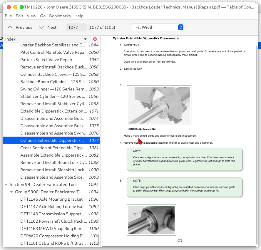
Cylinder Extendible Dipperstick Disassemble
Cross Section of Extendible Dipperstick Cylinder
Assemble Extendible Dipperstick Cylinder
Remove and Install Boom Lock Cylinder—315SG
Remove and Install Sideshift Lock Valve—315SG
Disassemble and Assemble Sideshift Lock Valve—315SG
Section 99: Dealer Fabricated Tool
Group 9900: Dealer Fabricated Tool
DFT1146 Axle Mounting Bracket
DFT1147 Axle Rolling Torque Bar
DFT1143 Transmission Support Bracket
DFT1162 Powershift Clutch Pack Snap Ring Removal and Installation Tool
DFT1163 MFWD Snap Ring Removal and Installation Tool
DFRW20 Compressor Holding Fixture
DFT1101 Cab and ROPS Lift Bracket
John Deere 315SG (S.N. BE315SG200039- ) Backhoe Loader Workshop Service Repair Manual


