Massey Ferguson MF3615, MF3625, MF3635, MF3645 Tractors Service Repair Manual (MMF4283084M2)
Catalog:
Model:
Complete service repair manual with Electrical Wiring Diagrams for Massey Ferguson MF3615, MF3625, MF3635, MF3645 Tractors, with all the technical information to maintain, diagnose, repair, rebuild like professional mechanics.
Massey Ferguson 3615, 3625, 3635, 3645 Tractors workshop service repair manual includes:
* Numbered table of contents easy to use so that you can find the information you need fast.
* Detailed sub-steps expand on repair procedure information
* Numbered instructions guide you through every repair procedure step by step.
* Troubleshooting and electrical service procedures are combined with detailed wiring diagrams for ease of use.
* Notes, cautions and warnings throughout each chapter pinpoint critical information.
* Bold figure number help you quickly match illustrations with instructions.
* Detailed illustrations, drawings and photos guide you through every procedure.
* Enlarged inset helps you identify and examine parts in detail.
PRODUCT DETAILS:
Total Pages: 2,331 pages
File Format: PDF (Internal Links, Bookmarked, Table of Contents, Searchable, Printable, high quality)
Language: English
1646965 M1 - Massey Ferguson 3615, 3625, 3635, 3645 Tractors Workshop Service Manual.pdf
4283084 M2 - Massey Ferguson 3615, 3625, 3635, 3645 Tractors Workshop Service Manual.pdf
Massey-Ferguson Tractor Series 3600 (Model MF 3615, MF3625, MF3635, MF3645) Workshop Service Manual.pdf
MAIN SECTIONS
00 TABLE OF CONTENT...2
01 Introduction and Safety...3
02 General Information and Specifications Assembly and Disassembly...11
03 Differential...279
04 Transmission...287
05 2WD Axle...641
06 Front Axle...689
07 Engine Sisu Fortius Series Drop...771
08 Amendment...772
TABLE OF CONTENTS
1646965 M1 - Massey Ferguson 3615, 3625, 3635, 3645 Tractors Workshop Service Manual...1
4283084M2 - Massey Ferguson 3615, 3625, 3635, 3645 Tractors Workshop Service Manual...717
00 TABLE OF CONTENT...718
01 Introduction and Safety...719
02 General Information and Specifications Assembly and Disassembly...727
03 Differential...995
04 Transmission...1003
05 2WD Axle...1357
06 Front Axle...1405
07 Engine Sisu Fortius Series Drop...1487
08 Amendment...1488
Massey-Ferguson Tractor Series 3600 (Model MF 3615, MF3625, MF3635, MF3645) Workshop Service Manual...1569
INTRODUCTION...1570
Indexing...1570
Definition of Terms...1570
Special Tools...1570
Repairs and Replacements...1570
Repair of the Tractor...1570
Amendments...1571
Safety Alert Symbol and Terms...1572
SAFETY IN THE WORKSHOP...1572
SAFETY - A WORD to the MECHANIC...1572
SAFETY - DANGER, WARNING and CAUTION...1572
SAFETY DECALS...1573
GENERAL...1573
PERSONAL CONSIDERATIONS...1573
Clothing...1573
Eye Protection...1573
Breathing Protection...1573
Hearing Protection...1573
Hand Protection...1573
Foot Protection...1573
Special Clothing...1573
EQUIPMENT CONSIDERATIONS...1573
Machine Guards...1573
Lifting Appliances...1573
Jacking...1573
Compressed Air...1574
Hand Tools...1574
Electricity...1574
GENERAL CONSIDERATIONS...1574
Solvents...1574
Housekeeping...1574
Fire...1574
First Aid...1574
OPERATIONAL CONSIDERATIONS...1575
SERVICING TECHNIQUES...1575
Service Safety...1575
Service Techniques...1576
Hoses and Tubes...1576
Bearings...1576
Shims...1576
Gaskets...1576
Lip Type Seals...1576
Use of Bolts in Blind Holes...1576
Locking Devices...1576
Cables and Wires...1576
2 MF3600-MT300B.pdf...0
Manual use...1580
Maintenance...1580
Repair...1580
Information property...1580
Agreements and definitions...1580
Agreements...1580
Definitions...1580
Typographic agreements...1580
Measurements...1580
Symbology...1581
General description...1582
General...1582
Hoses and Tubes...1582
O-Ring Flat Face Seal Fittings...1582
Shimming...1582
Rotating Shaft Seals...1582
O-Rings...1583
Bearings...1583
Spring Pins...1583
Hardware Torque Values...1583
Notes for Spare Parts...1583
Notes for Equipment...1583
Notices...1583
How to Move the Machine with the Battery Removed...1583
Product identification...1586
CAB...1588
PLATFORM TRACTORS...1588
PLATFORM TRACTORS...1588
General description...1590
TARE WEIGHTS kg (lb)*...1592
MAX PERMISSIBLE WEIGHTS kg (lb)...1593
TARE WEIGHTS kg (lb)*...1593
MAX PERMISSIBLE WEIGHTS kg (lb)...1594
DIMENSIONS WITH PLATFORM...1595
DIMENSIONS WITH CAB...1596
Steering angle...1597
Steering radius...1597
Travel speed...1598
Tyre...1603
Tyre pressure...1603
Battery...1607
DESCRIPTION AND OPERATION...1607
BATTERY REPLACEMENT...1607
MAINTENANCE...1608
SERVICING...1608
DRY CHARGED...1609
CHARGING THE BATTERY...1609
NORMAL (TOP-UP) CHARGING...1609
RECHARGING DEEPLY DISCHARGED...1609
TESTS...1609
SPECIFIC GRAVITY...1610
PERFORMANCE TEST...1610
TEST CHARGING...1611
COMMON CAUSES OF BATTERY FAILURES...1611
Emergency starting through another battery...1612
Battery connection using suitable cables...1612
Alternator...1614
GENERAL MAINTENANCE TABLE...1615
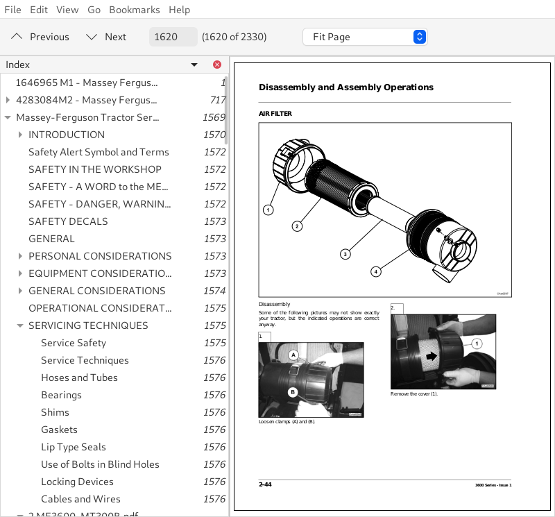
Air filter...1620
Disassembly...1620
Assembly...1622
Air filter line...1623
Disassembly...1623
Assembly...1625
Battery...1626
Disassembly...1626
Assembly...1627
Alternator...1629
Disassembly...1629
Assembly...1631
Radiator...1633
Disassembly...1634
Assembly...1637
Fan...1640
Disassembly...1640
Assembly...1641
Exhaust pipe...1642
Disassembly...1642
Assembly...1643
Fan belt...1644
Disassembly...1644
Assembly...1646
Air filter assy replacement...1648
Disassembly...1648
Assembly...1649
Bonnet...1651
Disassembly...1651
Assembly...1653
Front weight...1654
Disassembly...1654
Assembly...1655
Oil cooler...1656
Disassembly...1656
Assembly...1657
Muffler...1658
Disassembly...1658
Assembly...1659
Hydraulic pump...1660
Disassembly...1660
Assembly...1661
Starting motor...1663
Disassembly...1663
Assembly...1664
Engine removal...1666
Disassembly...1667
Assembly...1669
Front frame fitting nuts location...1672
Final operations...1672
Front axle 2WD...1673
Disassembly...1673
Assembly...1674
2WD front axle lubrication points...1676
Adjustment of steering angle...1676
Adjusting the tracks...1678
Fuel tank...1679
Disassembly...1679
Assembly...1681
Fuel level sensor disassembly...1682
Fuel level sensor assembly...1683
Brake cylinder...1684
Disassembly...1684
Assembly...1686
Hand brake adjustment...1687
Disassembly...1687
Assembly...1688
Lock valve...1690
Disassembly...1690
Assembly...1692
Rockshaft valve...1695
Disassembly...1695
Assembly...1697
Rear wheels...1699
Disassembly...1699
Assembly...1700
Auxiliary distributors...1701
Disassembly...1701
Assembly...1703
Oil suction strainer...1705
Disassembly...1705
Assembly...1706
Oil filter cartridge replacement...1707
Disassembly...1707
Assembly...1708
Side auxiliary distributors...1710
Disassembly...1710
Assembly...1711
Powershuttle hydraulic valve...1713
ON-OFF valve disassembly...1713
Flow divider valve disassembly...1714
Proportional valve disassembly...1715
Temperature sensor disassembly...1716
ON-OFF valve assembly...1716
Flow divider valve assembly...1717
Proportional valve assembly...1718
Oil filter sensor...1720
Disassembly...1720
Assembly...1721
Clutch box...1722
Disassembly...1722
Assembly...1727
Rockshaft...1732
Disassembly...1733
Assembly...1736
Platform...1739
Disassembly...1740
Assembly...1745
Steering valve...1751
Disassembly...1752
Assembly...1753
Brake circuit bleeding...1756
Disassembly/Assembly...1756
Electric diagram...2322
HI-LO power harness...2323
Massey Ferguson bonnet line...2323
Preheating harness...2323
MF3600 engine line...2323
Beacon light line...1796
NA right turn signal light line...1797
NA left turn signal light line...1798
Cab rear beam line...1799
Alternator cable...1800
Battery positive...1801
Battery negative...1802
Ground connector...1803
License plate light extension...1804
Beams extension...1805
Connector PTO 540 only...1806
NA cab front beam line...1807
Cab swinging beam extension...1808
Hydraulic system components...1810
Major components:...1810
Troubleshooting...1819
Axle problems and diagnosis...1821
SPECIFICATIONS...1824
TECHNICAL FEATURES...1824
DIMENSIONAL FEATURES...1824
CALIBRATION SETTINGS OF CONTROL VALVE...1824
diagram...1825
Circuit diagram of hydraulic lifting device...1826
Functioning of Control Valve...1827
Neutral Phase...1827
Delivery Phase...1828
Discharge Phase...1829
HOW THE Internal Leverage System Functions...1830
Functioning with position control (Fig. page 5.2)...1830
Functioning of Draft Control (Fig. page 5.2 - 5.4)...1832
Combined Functioning of Position and Draft Control (Fig. page 5.2-5.4)...1834
use of control Levers...1835
Position Control (lever 1)...1835
Draft Control (lever 2)...1835
Combined Operation for Position and Draft Control...1835
adjustment of Control Valve Sensitivity...1836
Functioning of the Sensitivity of the Control Valve...1836
ADJUSTMENT OF POSITION CONTROL LEVER...1838
ADJUSTMENT OF DRAFT CONTROL LEVER...1839
CONTROL OF ASSEMBLY OF REACTION SPRING...1840
MEASUREMENT CONTROL OF PUSH ROD...1841
DIAGNOSTIC...1842
3 Procedures.pdf...0
Disassembly...1847
Assembly...1848
4B CA357471.pdf...0
Intended use...1856
Product identification...1856
Transmission tag...1856
Technical features...1857
Main features...1857
8+8 synchro shuttle...1858
Mechanical controlled brakes features...1859
Technical features...1860
Main features...1860
GD PTO total ratio...1860
12+12 synchro shuttle...1861
Technical features...1862
Principal characteristics...1862
24+24 synchro shuttle and synchro splitter...1863
Technical features...1864
Main features...1864
24+24 synchro shuttle and power splitter...1865
Technical features...1866
Main features...1866
12 + 12 power shuttle...1867
Technical features...1868
Main features...1868
24 + 24 power shuttle and synchro splitter...1869
Main dimensions (millimeters) Left side view (see: main view)...1870
Tightening torques, sealants and grease application...1871
Drop box...1872
Front gear box...1873
Details...1874
Front gear boX...1875
Details...1876
Front gear box...1877
Details...1878
Front gear box...1879
Details...1880
Front gear box...1881
Details...1882
Gear box group...1883
Gear box details...1884
Final drive group (from 55 to 75 HP)...1885
Final drive group (85 HP)...1886
PTO shaft assy (540)...1887
PTO shaft assy (540-540E)...1888
PTO shaft assy (540-1000)...1889
GD-PTO and PTO shaft assy (540)...1890
GD-PTO and PTO shaft assy (540-540E)...1891
GD-PTO and PTO shaft assy (540-1000)...1892
Upper and lower cover...1893
Brake control assy...1894
Inner speed lever assy...1895
Inner speed lever assy...1896
Inner speed lever assy...1897
Inner speed lever assy...1898
Outer speed lever assy...1899
Hi/LO Power flows...1900
Hi/LO Power flows...1901
Power flows...1902
Power flows...1903
Power flows...1904
Power flows...1905
Power flows...1906
Power flows...1907
Assembly typical data...1908
Filling and checks...1919
Scheduled maintenance oil drain...1919
Scheduled maintenance oil filling...1919
Scheduled maintenance oil level check...1919
Filling and check points...1920
8+8 synchro shuttle...1921
12+12 synchro shuttle...1922
24+24 synchro shuttle and synchro splitter...1923
24+24 synchro shuttle and power splitter...1924
12 + 12 power shuttle...1925
24 + 24 power shuttle and synchro splitter...1926
Service schedule...1927
Lubricants application range...1927
Hydraulic system assy...1930
Disassembly...1931
Assembly...1939
Drop box...1947
Disassembly...1947
Assembly...1948
Final drive - from 55 to 75 HP...1949
Disassembly...1949
Assembly...1950
End float...1951
Final drive - 85 HP...1954
Disassembly...1954
Assembly...1955
Taper roller bearings preloading...1956
Teflon seals replacement (clutch shaft)...1958
Replacement...1959
Input shaft and support...1962
Disassembly...1962
Assembly...1965
Upper covers and rockshaft...1968
Disassembly...1968
Assembly...1969
Speed and ranges levers...1972
Disassembly...1972
Assembly...1973
Clutch housing - synchro shuttle...1975
Disassembly...1975
Assembly...1975
Clutch Housing - Synchro splitter...1977
Disassembly...1978
Assembly...1978
Synchro shuttle and Power splitter...1982
Disassembly...1983
Assembly...1983
Power shuttle - Power shuttle and Synchro splitter...1985
Disassembly...1986
Assembly...1988
Air compressor...1991
Disassembly...1992
Assembly...1992
Wet clutch - Power splitter...1993
Disassembly...1994
Assembly...1996
Clutch pack wear...2001
Wet clutch - Power shuttle...2004
Disassembly...2005
Assembly...2008
Clutch pack wear...2013
CLUTCH KIT...2014
Hi-LO synchronizer (synchro splitter)...2016
Disassembly...2016
Assembly...2017
Cover and PTO wet clutch...2020
Disassembly...2021
Assembly...2026
Clutch pack wear...2033
CLUTCH KIT...2034
PTO - Power take off...2035
Disassembly...2036
Assembly...2039
PTO Input shaft...2042
Disassembly...2043
Assembly...2044
PTO Output shaft...2046
Disassembly...2047
Assembly...2048
PTO Brake...2049
Disassembly...2050
Assembly...2053
Ground Drive PTO...2056
Disassembly...2057
Assembly...2057
Slave cylinder...2062
Disassembly...2063
Actuator assembly...2065
Parking brake...2067
Disassembly...2068
Assembly...2072
Housing sensors assy...2076
Disassembly...2077
Assembly...2078
Differential locking control...2080
Disassembly...2080
Assembly...2080
Inner control assy...2085
Disassembly...2086
Assembly...2086
Idle gear...2096
Synchro Shuttle...2096
Disassembly...2096
Assembly...2096
Power shuttle...2098
Disassembly...2098
Assembly...2100
Range gears (primary shaft)...2104
Disassembly...2106
Assembly...2107
Input shaft - synchro shuttle...2109
Disassembly...2110
Input shaft - 12+12 power shuttle...2116
Disassembly...2116
Assembly...2119
Synchronizer shuttle (replacement)...2122
Disassembly...2123
Assembly...2125
Speed gears (PRIMARY SHAFT)...2127
Disassembly...2127
Assembly...2128
Primary shaft covers...2130
Differential assy...2135
Disassembly...2135
Assembly...2136
Pinion - Ranges Pinion - Ranges (SECONDARY SHAFT)...2141
Disassembly...2141
Assembly...2142
secondary shaft...2147
Disassembly...2147
Assembly...2148
Speed gears (secondary shaft)...2153
Disassembly...2153
Assembly...2154
End floats 1 and 2 determination...2159
Special tools...2162
Drop box...2162
Gear box...2164
Clutch housing (12+12 Power shuttle)...2171
Wet clutch (Power shuttle)...2174
Wet clutch (Power splitter)...2177
Final drive - from 55 to 75 HP...2180
Final drive - 85 HP...2182
Clutch housing (synchro shuttle - synchro splitter...2184
Cover and PTO wet clutch...2187
Clutch housing (Synchro shuttle - Synchro splitter...2191
Clutch housing (synchro shuttle and Power splitter)...2194
Clutch housing (synchro shuttle)...2197
5A CA357465.pdf...0
Manual use...2204
Maintenance...2204
Repair...2204
Information property...2204
Agreements and definitions...2204
Agreements...2204
Definitions...2204
Typographic agreements...2204
Measurements...2204
Conversion table...2205
Symbology...2206
General description...2207
Recommendations for repair operations...2207
Shafts seals...2207
O-rings...2207
Bearings...2207
Sealing...2207
Cleaning...2207
Checks...2207
Ends of flanges and tools...2207
Assembly methods...2207
Intended use...2210
Product identification...2210
Axle tag...2210
General description...2210
Technical Features...2211
Main dimensions (mm)...2212
Maintenance...2213
Service schedule...2214
Lubricants application range...2214
Grease in assembly...2215
Adhesive and sealant...2216
Sealing compounds and adhesives...2217
Tightening torques...2218
Steering cylinder group...2220
Disassembly...2220
Assembly...2221
Wheel hub group...2224
Disassembly...2224
Assembly...2225
Wheel hub support group...2227
Disassembly...2227
Assembly...2228
Axle beam group...2230
Disassembly...2230
Assembly...2231
Toe-in/steering angle...2233
Toe-in adjustment...2233
Steering angle adjustment...2235
Troubleshooting...2239
Axle problem and diagnosis...2239
Special tools...2242
Service operations time schedule...2246
Steering Cylinder Group...2246
Wheel Hub Group...2246
Spindle Group...2247
Axle Beam Group...2247
5B CA357464.pdf...0
Manual use...2252
Maintenance...2252
Repair...2252
Information property...2252
Agreements and definitions...2252
Agreements...2252
Definitions...2252
Typographic agreements...2252
Measurements...2252
Conversion table...2253
Symbology...2254
General description...2255
Recommendations for repair operations...2255
Shafts seals...2255
O-rings...2255
Adjusting shims...2255
Bearings...2255
Split pins...2255
Sealing...2255
Oil drain...2255
Cleaning...2256
Checks...2256
Ends of flanges and tools...2256
Lubricant use...2256
Intended use...2258
Product identification...2258
Axle serial plate...2258
General description...2259
Technical Features...2260
Limited slip differential disks specifications...2261
Principal Dimensions (mm)...2262
Maintenance and oil change...2263
Service schedule...2266
Lubricants application range...2266
Grease in assembly...2267
Adhesive and sealant...2268
Sealing compounds and adhesives...2269
Tightening torques...2271
Steering cylinder group...2274
Disassembly...2274
Assembly...2275
Epicyclic reduction gear group...2277
Disassembly...2277
Assembly...2278
Wheel hub group...2280
Disassembly...2280
Assembly...2283
Axle beam group...2286
Disassembly...2286
Assembly...2287
Trunnions group...2289
Disassembly...2289
Assembly...2290
Differential support group...2293
Disassembly...2293
Assembly...2294
Bevel gear marking test...2298
Differential group...2299
Disassembly...2299
Assembly...2300
Pinion group...2302
Disassembly...2302
Assembly...2303
Toe-in/steering angle...2307
Toe-in adjustment...2307
Steering angle adjustment...2308
Special repair operations...2310
Wheel and double U-joint group disassembly...2310
Wheel and double U-joint group assembly...2311
Double U-joint seal ring replacement on axle beam side...2312
Double U-joint bushing replacement on axle beam side...2313
Testing after assembly...2314
Testing methods...2314
Troubleshooting...2317
Axle problem and diagnosis...2319
Special tools...2322
Service operations time schedule...2326
Steering Cylinder Group (G3)...2326
Epicyclic Reduction Gear Group (G1)...2326
Wheel Hub Group (G1)...2327
Axle Beam Group (G4)...2327
Trunnions Group (G2-G4)...2328
Differential Support Group (G2)...2328
Differential Group (G2)...2328
Pinion Group...2329
Massey Ferguson MF3615, MF3625, MF3635, MF3645 Tractors Service Repair Manual (MMF4283084M2)


