John Deere Skid Steer & Compact Track Loaders 319E, 323E (EH Controls) Workshop Service Repair Manual
Catalog:
Model:
John Deere Skid Steer & Compact Track Loaders 319E, 323E (EH Controls) Workshop Service Repair manual with Electrical Wiring Diagrams (including maintenance, overhaul, disassembling & assembling, adjustment, tune-up, operation, inspecting, diagnosis & troubleshooting…) is divided into different sections. Each section covers a specific component or system with detailed illustrations. A table of contents is placed at the beginning of each section. Pages are easily found by category, and each page is expandable for great detail. The printer-ready PDF documents work like a charm on all kinds of devices.
This manual contains high quality images, circuit diagrams, instructions to help you to maintenance, troubleshoot, diagnose, and repair. This document is printable, without restrictions, contains searchable text, bookmarks, crosslinks for easy navigation.
TM13087X19 - John Deere Skid Steer & Compact Track Loaders 319E, 323E (EH Controls) Technical Manual (Operation and Test).pdf
tm13087x28 - John Deere 319E et 323E Chargeur compact à chenilles (Commandes EH).pdf
Category: Operation and Test
Language: English French
Published on 2019/10/16
TABLE OF CONTENTS
Section 9000: General Information....23
Group 01: Safety....23
Recognize Safety Information....26
Follow Safety Instructions....27
Operate Only If Qualified....28
Wear Protective Equipment....29
Avoid Unauthorized Machine Modifications....30
Inspect Machine....31
Stay Clear of Moving Parts....32
Avoid High-Pressure Fluids....33
Avoid High-Pressure Oils....34
Work In Ventilated Area....35
Prevent Fires....36
Prevent Battery Explosions....37
Handle Chemical Products Safely....38
Decommissioning — Proper Recycling and Disposal of Fluids and Components....39
Prepare for Emergencies....40
Clean Debris from Machine....41
Use Steps and Handholds Correctly....42
Start Only From Operator's Seat....43
Use and Maintain Seat Belt....44
Prevent Unintended Machine Movement....45
Avoid Work Site Hazards....46
Keep Riders Off Machine....48
Avoid Backover Accidents....49
Avoid Machine Tip Over....50
Operating On Slopes....51
Operating or Traveling On Public Roads....52
Inspect and Maintain ROPS....53
Add and Operate Attachments Safely....54
Park and Prepare for Service Safely....55
Service Cooling System Safely....56
Remove Paint Before Welding or Heating....57
Make Welding Repairs Safely....58
Drive Metal Pins Safely....59
Handle Cab Door Safely....60
Section 9001: Diagnostic Trouble Codes (DTCs)....61
Group 10: Engine Control Unit (ECU) Diagnostic Trouble Codes....71
Engine Control Unit (ECU) Diagnostic Trouble Codes....71
000029.00 - Foot Throttle....61
000029.01 - Foot Throttle....61
000029.02 - Foot Throttle....61
000029.03 - Foot Throttle....61
000029.04 - Foot Throttle....61
000029.08 - Foot Throttle....61
000029.15 - Foot Throttle....61
000091.00 - Acceleration / Sensor 1....61
000091.01 - Acceleration / Sensor 1....61
000091.02 - Acceleration / Sensor 1....61
000091.03 - Acceleration / Sensor 1....61
000091.04 - Acceleration / Sensor 1....61
000091.15 - Acceleration / Sensor 1....61
000100.01 - Oil Pressure Switch....61
000100.04 - Oil Pressure Switch....61
000167.01 - Charging System Voltage Extremely Low....61
000167.04 - Charging System Voltage Out of Range Low....61
000639.12 - Communication System....61
001202.02 - Anti Theft Password Representation....61
001485.04 - Main Relay / ECU....61
001485.07 - Main Relay / ECU....61
522242.02 - Cold Start Aid Solenoid....61
522242.03 - Cold Start Aid Solenoid....61
522242.04 - Cold Start Aid Solenoid....61
522243.02 - Start Assist / Relay....61
522243.03 - Start Assist / Relay....61
522243.04 - Start Assist / Relay....61
522243.05 - Start Assist / Relay....61
522243.06 - Start Assist / Relay....61
522323.00 - Air Filter Pressure Differential Extremely High....61
522402.04 - Auxiliary Speed Sensor....62
522596.09 - ECU Communication Fault....62
522597.09 - ECU Communication Fault....62
522599.09 - ECU Communication Fault....62
522600.09 - ECU Communication Fault....62
522601.09 - ECU Communication Fault....62
522609.09 - ECU Communication Fault....62
522618.09 - ECU Communication Fault....62
522619.09 - ECU Communication Fault....62
522730.12 - Vehicle Immobilizer System CAN Communication Error....62
Group 20: Engagement and Monitor Unit (EMU) Diagnostic Trouble Codes....169
Engagement and Monitor Unit (EMU) Diagnostic Trouble Codes....169
000070.02 - Park Brake / Release Input....62
000070.04 - Park Brake / Release Input....62
000096.03 - Fuel Level / Sensor....62
000096.04 - Fuel Level / Sensor....62
000158.00 - System Voltage....62
000158.01 - System Voltage....62
000162.04 - 2-Speed / Switch Input....62
000234.14 - Software Mismatch....62
000920.05 - Alarm Output....62
000920.06 - Alarm Output....62
001196.11 - Anti Theft....62
001504.04 - Seat Switch / Input....62
002000.09 - No ECU Data / On CAN Bus....62
002142.09 - No SSM Data / On CAN Bus....62
002228.09 - No HCU Data / On CAN Bus....62
003413.04 - Door Switch / Input....62
003597.03 - 5 Volt Sensor / Supply 1....62
003597.04 - 5 Volt Sensor / Supply 1....62
521050.04 - Aux Flow On-Off / Switch Input....62
521197.04 - Courtesy Light / Switch Input....62
522379.05 - Park Brake / Release Output....62
522379.06 - Park Brake / Release Output....63
522398.02 - Park Brake Run / Switch Input....63
522398.04 - Park Brake Run / Switch Input....63
522826.00 - Fan Purge / Switch Input....63
522826.04 - Fan Purge / Switch Input....63
522827.04 - Fan Auto / Switch Input....63
522828.03 - Creep Mode/ Switch Input....63
522828.04 - Creep Mode/ Switch Input....63
522828.07 - Creep Mode/ Switch Input....63
522859.04 - Lap Bar/ Switch Input....63
523217.06 - Hydraulic Valve / Power 3 to HCU....63
523218.06 - Propel Valve / Power 2 to HCU....63
523219.06 - Hydraulic Valve / Power Output....63
523693.03 - Aux Hyd / Channel 1 Input....63
523693.04 - Aux Hyd / Channel 1 Input....63
523694.03 - Aux Hyd / Channel 2 Input....63
523694.04 - Aux Hyd / Channel 2 Input....63
523694.12 - Aux Hyd / Channel 2 Input....63
523822.04 - High Flow / Switch Input....63
523935.05 - Aux Hyd / Extend Output....63
523935.06 - Aux Hyd / Extend Output....63
523941.05 - Aux Hyd / Retract Output....63
523941.06 - Aux Hyd / Retract Output....63
523948.05 - Ride Control 1 / Solenoid Current....63
523948.06 - Ride Control 1 / Solenoid Current....63
523949.05 - Ride Control 2 / Solenoid Current....63
523949.06 - Ride Control 2 / Solenoid Current....63
524225.04 - Remote Start / Input....63
524264.11 - Checksum Error....63
Group 30: Hydraulic Control Unit (HCU) Diagnostic Trouble Codes....307
Hydraulic Control Unit (HCU) Diagnostic Trouble Codes....307
000630.13 - Cal Missing / Or Incomplete....63
001594.00 - Left Speed / Sensor Input....63
001594.01 - Left Speed / Sensor Input....64
001594.02 - Left Speed / Sensor Input....64
001594.14 - Left Speed / Sensor Input....64
001595.00 - Right Speed / Sensor Input....64
001595.01 - Right Speed / Sensor Input....64
001595.02 - Right Speed / Sensor Input....64
001595.14 - Right Speed / Sensor Input....64
002201.09 - Right Joystick / CAN Data....64
002213.09 - Left Joystick / CAN Data....64
002660.07 - Right Joystick / X-Axis....64
002661.07 - Right Joystick / Y-Axis....64
002697.07 - Left Joystick / X-Axis....64
002698.07 - Left Joystick / Y-Axis....64
516193.03 - Left Foot Pedal / Signal 1....64
516193.04 - Left Foot Pedal / Signal 1....64
516193.07 - Left Foot Pedal / Signal 1....64
516193.16 - Left Foot Pedal / Signal 1....64
516193.18 - Left Foot Pedal / Signal 1....64
516194.03 - Left Foot Pedal / Signal 2....64
516194.04 - Left Foot Pedal / Signal 2....64
516195.03 - Right Foot Pedal / Signal 2....64
516195.04 - Right Foot Pedal / Signal 2....64
516196.03 - Right Foot Pedal / Signal 1....64
516196.04 - Right Foot Pedal / Signal 1....64
516196.07 - Right Foot Pedal / Signal 1....64
516196.16 - Right Foot Pedal / Signal 1....64
516196.18 - Right Foot Pedal / Signal 1....64
520652.05 - Bucket Curl / Solenoid Current....64
520652.06 - Bucket Curl / Solenoid Current....64
520652.16 - Bucket Curl / Solenoid Current....64
520653.05 - Bucket Dump / Solenoid Current....64
520653.06 - Bucket Dump / Solenoid Current....64
520653.16 - Bucket Dump / Solenoid Current....64
522377.03 - Boom Sensor / Signal 1....65
522377.04 - Boom Sensor / Signal 1....65
522377.12 - Boom Sensor / Signal 1....65
522377.13 - Boom Sensor / Signal 1....65
523378.03 - Boom Sensor / Signal 2....65
523378.04 - Boom Sensor / Signal 2....65
522436.03 - Bucket Sensor / Signal 1....65
522436.04 - Bucket Sensor / Signal 1....65
522436.12 - Bucket Sensor / Signal 1....65
522436.13 - Bucket Sensor / Signal 1....65
522437.03 - Bucket Sensor / Signal 2....65
522437.04 - Bucket Sensor / Signal 2....65
522447.05 - Right Pump / Fwd Sol Current....65
522447.06 - Right Pump / Fwd Sol Current....65
522447.16 - Right Pump / Fwd Sol Current....65
522448.05 - Right Pump / Rev Sol Current....65
522448.06 - Right Pump / Rev Sol Current....65
522448.16 - Right Pump / Rev Sol Current....65
522449.05 - Left Pump / Rev Sol Current....65
522449.06 - Left Pump / Rev Sol Current....65
522449.16 - Left Pump / Rev Sol Current....65
522450.05 - Left Pump / Fwd Sol Current....65
522450.06 - Left Pump / Fwd Sol Current....65
522450.16 - Left Pump / Fwd Sol Current....65
523217.03 - Hydraulic Valve / Power 3 to HCU....65
523217.04 - Hydraulic Valve / Power 3 to HCU....65
523218.03 - Propel Valve / Power 2 to HCU....65
523218.04 - Propel Valve / Power 2 to HCU....65
523219.03 - Hydraulic Valve / Power 1 to HCU....65
523219.04 - Hydraulic Valve / Power 1 to HCU....65
523411.05 - Boom Down / Solenoid Current....65
523411.06 - Boom Down / Solenoid Current....65
523411.16 - Boom Down / Solenoid Current....65
523414.05 - Boom Up / Solenoid Current....66
523414.06 - Boom Up / Solenoid Current....66
523414.16 - Boom Up / Solenoid Current....66
Group 40: Left Joystick Controller (JSL) Diagnostic Trouble Codes....490
Left Joystick Controller (JSL) Diagnostic Trouble Codes....490
002697.03 - Left Joystick / X-Axis....66
002697.04 - Left Joystick / X-Axis....66
002697.13 - Left Joystick / X-Axis....66
002697.14 - Left Joystick / X-Axis....66
002698.03 - Left Joystick / Y-Axis....66
002698.04 - Left Joystick / Y-Axis....66
002698.13 - Left Joystick / Y-Axis....66
002698.14 - Left Joystick / Y-Axis....66
Group 50: Right Joystick Controller (JSR) Diagnostic Trouble Codes....500
Right Joystick Controller (JSR) Diagnostic Trouble Codes....500
002660.03 - Right Joystick / X-Axis....66
002660.04 - Right Joystick / X-Axis....66
002660.13 - Right Joystick / X-Axis....66
002660.14 - Right Joystick / X-Axis....66
002661.03 - Right Joystick / Y-Axis....66
002661.04 - Right Joystick / Y-Axis....66
002661.13 - Right Joystick / Y-Axis....66
002661.14 - Right Joystick / Y-Axis....66
Group 60: Sealed Switch Module (SSM) Diagnostic Trouble Codes....510
Sealed Switch Module (SSM) Diagnostic Trouble Codes....510
0000629.12 - Controller Fault....66
002033.09 - VCU CAN Comm....66
002634.04 - Ignition Relay....66
002634.05 - Ignition Relay....66
523850.04 - SSM Button 15....66
523850.09 - SSM Button 15....66
523852.04 - SSM Button 14....66
523852.09 - SSM Button 14....66
523854.04 - SSM Button 13....67
523854.09 - SSM Button 13....67
523855.04 - SSM Button 12....67
523855.09 - SSM Button 12....67
523856.04 - SSM Button 11....67
523856.09 - SSM Button 11....67
523857.04 - SSM Button 10....67
523857.09 - SSM Button 10....67
523858.04 - SSM Button 9....67
523858.09 - SSM Button 9....67
523860.04 - SSM Button 8....67
523860.09 - SSM Button 8....67
523861.04 - SSM Button 7....67
523861.09 - SSM Button 7....67
523862.04 - SSM Button 6....67
523862.09 - SSM Button 6....67
523863.04 - SSM Button 5....67
523863.09 - SSM Button 5....67
523864.04 - SSM Button 4....67
523864.09 - SSM Button 4....67
523865.04 - SSM Button 3....67
523865.09 - SSM Button 3....67
523867.04 - SSM Button 2....67
523867.09 - SSM Button 2....67
523868.04 - SSM Button 1....67
523868.09 - SSM Button 1....67
Group 70: Vehicle Control Unit (VCU) Diagnostic Trouble Codes....584
Vehicle Control Unit (VCU) Diagnostic Trouble Codes....584
000091.03 - Accelerator 2 - Pedal Voltage Above Normal....67
000091.04 - Accelerator 2 - Pedal Voltage Below Normal....67
000158.03 - Battery Voltage Switched Power....67
000158.04 - Battery Voltage Switched Power....67
000168.03 - Unswitched Power / Input....67
000168.04 - Unswitched Power / Input....68
000977.05 - Fan Direction / Mode....68
000977.06 - Fan Direction / Mode....68
001071.05 - Fan Speed / Solenoid....68
001071.06 - Fan Speed / Solenoid....68
001508.00 - Hydraulic Oil / Temperature....68
001508.03 - Hydraulic Oil / Temperature....68
001508.04 - Hydraulic Oil / Temperature....68
001713.00 - Hydraulic Filter / Restr Switch....68
001713.03 - Hydraulic Filter / Restr Switch....68
003512.03 - 5 Volt Sensor / Supply 4....68
003512.04 - 5 Volt Sensor / Supply 4....68
003597.03 - 5 Volt Sensor / Supply 1....68
003597.04 - 5 Volt Sensor / Supply 1....68
003598.03 - 5 Volt Sensor / Supply 2....68
003598.04 - 5 Volt Sensor / Supply 2....68
003599.03 - 5 Volt Sensor - Supply 3....68
003599.04 - 5 Volt Sensor - Supply 3....68
004056.05 - 2-Speed Output....68
004056.06 - 2-Speed Output....68
520194.13 - Machine Model ID / Wrong or Missing....68
520194.14 - Machine Model ID / Wrong or Missing....68
520849.03 - Right Joystick / Trigger Input....68
520849.04 - Right Joystick / Trigger Input....68
521466.05 - Fan Direction / Relief....68
521466.06 - Fan Direction / Relief....68
521806.05 - HST Bypass Solenoid....68
521806.06 - HST Bypass Solenoid....68
522820.05 - High Flow / Driver....68
522820.06 - High Flow / Driver....68
524084.00 - Hydrostat Oil / Temperature....68
524084.03 - Hydrostat Oil / Temperature....68
524084.04 - Hydrostat Oil / Temperature....68
524264.11 - Checksum Error....69
Section 9005: Operational Checkout Procedure....697
Group 10: Operational Checkout Procedure....697
Operational Checkout....730
Section 9010: Engine....762
Group 05: Theory of Operation....762
John Deere Engine....772
Engine Identification....765
Cold Start Operation....768
Group 15: Diagnostic Information....762
John Deere Engine....772
Engine Cooling System Component Location....773
Engine Fuel System Component Location....775
Engine Intake and Exhaust Component Location....777
Engine Hard to Start or Does Not Start When Cold....762
Section 9015: Electrical System....781
Group 05: System Information....781
Electrical Diagram Information....788
Electrical Schematic Symbols....791
Group 10: System Diagrams....781
Fuse and Relay Specifications....800
System Functional Schematic, Wiring Diagram and Component Location Master Legend....806
System Functional Schematic....813
Rear Engine Harness (W1) Component Location....821
Rear Engine Harness (W1) Wiring Diagram....823
Cab Harness (W2) Component Location....825
Cab Harness (W2) Wiring Diagram....829
Main Harness (W3) Component Location....834
Main Harness (W3) Wiring Diagram....842
Dual Flasher Harness (W5) Component Location....857
Dual Flasher Harness (W5) Wiring Diagram....858
Radio Harness (W8) Component Location....860
Radio Harness (W8) Wiring Diagram....861
Hydraulic Valve Harness (W10) Component Location....862
Hydraulic Valve Harness (W10) Wiring Diagram....864
Attachment Control Frame Harness (W11) Component Location....865
Attachment Control Frame Harness (W11) Wiring Diagram....866
Attachment Control Boom Harness (W12) Component Location....867
Attachment Control Boom Harness (W12) Wiring Diagram....868
Quik-Tatch™ Frame Harness (W13) Component Location....869
Quik-Tatch™ Frame Harness (W13) Wiring Diagram....870
Quik-Tatch™ Boom Harness (W14) Component Location....871
Quik-Tatch™ Boom Harness (W14) Wiring Diagram....872
Quik-Tatch™ Actuator Harness (W15) Component Location....873
Quik-Tatch™ Actuator Harness (W15) Wiring Diagram....874
Heater and Air Conditioner Harness (W16) Component Location....875
Heater and Air Conditioner Harness (W16) Wiring Diagram....877
Hydrostatic Control Valve Harness (W17) Component Location....878
Hydrostatic Control Valve Harness (W17) Wiring Diagram....879
High/Low Pressure Switch and Heater Valve Motor Harness (W18) Component Location....880
High/Low Pressure Switch and Heater Valve Motor Harness (W18) Wiring Diagram....882
Creep Mode Speed Switch Harness (W19) Component Location....884
Creep Mode Speed Switch Harness (W19) Wiring Diagram....885
Left Pedal Sensor Harness (W23) Component Location....886
Left Pedal Sensor Harness (W23) Wiring Diagram....887
Right Pedal Sensor Harness (W24) Component Location....888
Right Pedal Sensor Harness (W24) Wiring Diagram....889
Hydrostatic Oil Temperature Sensor Harness (W25) Component Location....890
Hydrostatic Oil Temperature Sensor Harness (W25) Wiring Diagram....891
License Plate Light Harness (W26) Component Location....892
License Plate Light Harness (W26) Wiring Diagram....893
Joystick Jumper Harness (W27) Component Location....894
Joystick Jumper Harness (W27) Wiring Diagram....895
Group 15: Sub-System Diagnostics....782
Starting Circuit Theory of Operation....905
Controller Area Network (CAN) Theory of Operation....914
Engine Control Unit (ECU) Circuit Theory of Operation....918
Engagement and Monitor Unit (EMU) Circuit Theory of Operation....926
Lighting Circuit Theory of Operation....936
Hydraulic System Control Circuit Theory of Operation....939
Hydrostatic System Control Circuit Theory of Operation....948
Hydraulic Fan Control Circuit Theory of Operation....959
Backup Alarm Circuit Theory of Operation....964
Quik-Tatch Circuit Theory of Operation—If Equipped....966
Group 16: Monitor Operation....782
Engagement and Monitor Unit Operation....971
Engagement and Monitor Unit Data Items....974
Engagement and Monitor Unit Display Messages....978
Engagement and Monitor Unit Service Menu Operation....981
Engagement and Monitor Unit Initial Configuration....983
Anti-Theft Security System Operation—If Equipped....985
Anti-Theft Security System Configuration—If Equipped....987
Anti-Theft Security System Enable—If Equipped....992
Group 20: References....783
Service ADVISOR™ Connection Procedure....997
Reading Diagnostic Trouble Codes (DTCs)....1000
Intermittent Diagnostic Trouble Code (DTC) Diagnostics....1004
Electrical Component Checks....1005
Electrical Component Specifications....1017
Solenoid Test....1024
Alternator Test....1053
Controller Area Network (CAN) Circuit Test....1057
Boom and Bucket Calibration....1068
Auxiliary Hydraulics Calibration....1070
Manual Tracking Adjustment Procedure....1072
Hydrostatic System Calibration....1073
Electrohydraulic (EH) Foot Pedal Calibration....1076
Engine Control Unit (ECU) Remove and Install....1078
Hydraulic Control Unit (HCU) Remove and Install....1080
Engagement and Monitor Unit (EMU) Remove and Install....1082
Control Panel Remove and Install....1085
Left Joystick Controller (JSL) Remove and Install....1087
Right Joystick Controller (JSR) Remove and Install....1091
Joystick Disassemble and Assemble....1095
Left Electrohydraulic (EH) Foot Pedal Remove and Install....1098
Right Electrohydraulic (EH) Foot Pedal Remove and Install....1099
Backup Alarm Remove and Install....1100
Battery Remove and Install....1101
Motor Speed Sensor Remove and Install....1102
Replace (Pull Type) Metri-Pack™ Connectors....1116
Replace (Push Type) Metri-Pack™ Connectors....1118
Replace Metri-Pack™ Connectors....1119
Replace WEATHER PACK WEATHER PACK is a trademark of Packard Electric. Connector....783
Install WEATHER PACK WEATHER PACK is a trademark of Packard Electric. Contact....783
Replace DEUTSCH DEUTSCH is a trademark of Deutsch Co. Rectangular or Triangular Connectors....784
Replace DEUTSCH DEUTSCH is a trademark of the Deutsch Co. Circular Connectors....784
Replace DEUTSCH DEUTSCH is a trademark of the Deutsch Co. Connectors....784
Install DEUTSCH DEUTSCH is a trademark of the Deutsch Co. Contact....784
Replace CINCH™ Connectors....1133
Install CINCH™ Contact....1135
Repair 32 and 48 Way CINCH™ Connectors....1137
Remove Connector Body from Blade Terminals....1141
Section 9020: Power Train....1142
Group 05: Theory of Operation....1142
Power Train System Operation....1144
Hydrostatic Motor Gear Case Operation....1145
Track Adjuster and Recoil Spring Operation....1146
Group 15: Diagnostic Information....1142
Power Train Component Location....1150
Loose Track....1142
Tight Track....1142
Frequent Track Tension Adjustment Required....1142
Excessive Oil Leakage From Idlers And Rollers....1142
Section 9025: Hydraulic System....1167
Group 05: Theory of Operation....1167
Hydraulic System Operation....1170
Hydraulic Oil Filter Manifold Operation....1171
High Flow Pump Operation—If Equipped....1172
Self Leveling Valve Operation—If Equipped....1176
Ride Control Operation—If Equipped....1178
Hydraulic Pump Operation....1180
Hydraulic Fan Operation....1182
Hydraulic Control Valve Operation....1196
Group 15: Diagnostic Information....1167
Hydraulic System Schematic....1211
Hydraulic System Component Location....1220
Diagnose Hydraulic System Malfunctions....1228
No Hydraulic Functions....1167
Boom Will Not Raise....1167
Boom Will Not Lower....1167
Bucket Will Not Dump....1167
Bucket Will Not Curl....1167
Bucket Will Not Self Level When Boom is Raised....1167
Bucket Dumps During Self Leveling Cycle....1167
Boom Drifts Down....1167
Boom Drifts Up....1167
Bucket Drifts Down....1167
Bucket Drifts Up....1167
Hydraulic Functions Slow or No Power....1167
Hydraulic Functions “Jerky” or “Spongy”....1167
Hydraulic System Noise....1167
Hydraulic Oil Overheats....1167
Hydraulic Fan System Malfunctions....1167
Hydraulic Fan Will Not Reverse Direction....1167
Group 20: Adjustments....1167
Ride Control Accumulator Gas Charge Procedure—If Equipped....1316
Group 25: Tests....1168
JT05800 Digital Thermometer Installation....1320
JT02156A Digital Pressure and Temperature Analyzer Kit Installation....1321
Remote Start Box Installation....1322
Hydraulic System Pressure Release....1324
Pilot Control Accumulator Precharge Test....1325
Port Lock Solenoid Valve and Port Lock Spool Test....1329
Hydraulic System Relief Valve Test....1330
Charge Pressure Relief Valve Test....1333
High Flow Relief Valve Test....1337
Circuit Relief Valve Test....1341
Function Drift Test....1350
Hydraulic Cylinder Leakage Test....1359
Hydraulic Pump Flow Test....1361
Charge Pump Flow Test....1368
Hydraulic Fan Motor Speed Test....1371
Hydraulic Fan Motor Case Drain Test....1378
Hydraulic Oil Cooler Bypass Valve Test....1387
Auxiliary Coupler Manifold Leakage Test....1391
Section 9026: Hydrostatic System....1393
Group 05: Theory of Operation....1393
Hydrostatic System Operation....1395
Hydrostatic Pump Operation....1396
Charge Pump Operation....1402
Hydrostatic Motor Operation....1404
Hydrostatic Control Valve Operation....1409
Park Brake System Operation....1411
Steering Control Operation....1413
Group 15: Diagnostic Information....1393
Hydrostatic System Schematic....1419
Hydrostatic System Component Location....1422
Machine Does Not Move In Either Direction....1393
Hydrostatic Pump Or Hydrostatic Motor Noise....1393
Slow Response To Changes In Speed....1393
Low Power....1393
Tracks Powered On One Side, Not The Other....1393
Machine Will Not Shift Into Or Out Of High Speed....1393
Mistracking....1393
Park Brakes Do Not Hold....1393
Park Brakes Do Not Release....1393
Grinding Noise While Operating Machine....1393
Group 25: Tests....1393
Engine Speed Control for Testing....1458
Multi-Function Valve Pressure Relief Test....1460
Hydrostatic Pump Flow Test....1464
Hydrostatic Pump Mechanical Neutral Adjustment....1470
Hydrostatic Pump Control Neutral Adjustment....1475
Track Speed Test....1478
Park Brake Release Pressure Test....1481
Section 9031: Heating and Air Conditioning....1485
Group 05: Theory of Operation....1485
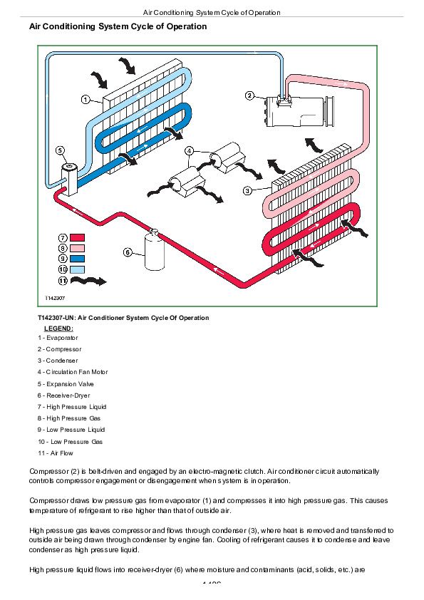
Air Conditioning System Cycle of Operation....1488
Group 15: Diagnostic Information....1485
Air Conditioning and Heater System Component Location....1492
Air Conditioning System Does Not Operate....1485
Air Conditioning Does Not Cool Interior of Cab....1485
Air Conditioner Runs Constantly, Too Cool....1485
Heater System Does Not Operate....1485
Heater Does Not Warm Interior of Cab....1485
Interior Windows Continue to Fog....1485
Group 25: Tests....1485
Refrigerant Cautions and Proper Handling....1518
Air Conditioner and Heater Operational Checks....1519
Refrigerant Leak Testing....1523
Air Conditioner Compressor Clutch Test....1524
Air Conditioning High/Low Pressure Switch Test....1526
Air Conditioner Freeze Control Switch Test....1530
R134a Refrigerant Cautions....1532
R134a Oil Charge Capacity....1533
R134a Refrigerant Charge Capacity....1534
Operating Pressure Diagnostic Chart....1535
Section 9900: Dealer Fabricated Tools....1540
Group 99: Dealer Fabricated Tools....1540
DFT1318 Motor Speed Sensor Test Harness....1543
DFT1325 Solenoid Power Harness....1545
John Deere Skid Steer & Compact Track Loaders 319E, 323E (EH Controls) Workshop Service Repair Manual (TM13087X19)


