John Deere Excavators 200D, 200DLC Technical Service Repair Manual (TM10079)
Catalog:
Model:
Complete service repair manual for John Deere Excavators 200D, 200DLC, with all the workshop information to maintain, repair & service like professional mechanics.
John Deere Excavators 200D, 200DLC workshop service repair manual includes:
* Numbered table of contents easy to use so that you can find the information you need fast.
* Detailed sub-steps expand on repair procedure information
* Numbered instructions guide you through every repair procedure step by step.
* Notes, cautions and warnings throughout each chapter pinpoint critical information.
* Bold figure number help you quickly match illustrations with instructions.
* Detailed illustrations, drawings and photos guide you through every procedure.
* Enlarged inset helps you identify and examine parts in detail.
TM10079 - John Deere 200D & 200DLC Excavator Technical Manual - Repair.pdf
TM10079 (14MAR19) - John Deere 200D & 200DLC Excavator Technical Manual - Repair.pdf
tm10080 - Excavatrices 200D et 200DLC.pdf
tm10081 - Excavadoras 200D y 200DLC.pdf
tm12021 - Escavadeiras 200D e 200DLC.pdf
Total Pages: 556 pages
File Format: PDF (bookmarked, ToC, Searchable, Printable)
Category: Repair
Language: Spanish English French Portuguese
MAIN SECTIONS
Foreword
Technical Information Feedback Form
General Information
Safety
Torque Values
Tracks
Track System
Axles, Differentials and Suspension Systems
Axle Shaft, Bearings, and Reduction Gears
Hydraulic System
Engine
Removal and Installation
Engine Auxiliary System
Cooling System
Intake System
External Fuel Supply System
Dampener Drive (Flex Coupling)
Elements
Frame or Supporting Structure
Frame Installation
Chassis Weights
Operator`s Station
Removal and Installation
Operator Enclosure
Seat and Seat Belt
Heating and Air Conditioning
Excavator
Buckets
Frames
Hydraulic System
Swing or Pivoting System
Mechanical Drive Elements
Hydraulic System
Dealer Fabricated Tools
tm10079 - 200D and 200DLC Excavator
Table of Contents
Foreword
Technical Information Feedback Form
Section 00: General Information
Group 01: Safety
Recognize Safety Information
Follow Safety Instructions
Operate Only If Qualified
Wear Protective Equipment
Avoid Unauthorized Machine Modifications
Add Cab Guarding for Special Uses
Inspect Machine
Stay Clear of Moving Parts
Avoid High-Pressure Fluids
Avoid High-Pressure Oils
Beware of Exhaust Fumes
Prevent Fires
Prevent Battery Explosions
Handle Chemical Products Safely
Dispose of Waste Properly
Prepare for Emergencies
Use Steps and Handholds Correctly
Start Only From Operator's Seat
Use and Maintain Seat Belt
Prevent Unintended Machine Movement
Avoid Worksite Hazards
Keep Riders Off Machine
Avoid Backover Accidents
Avoid Machine Tip Over
Use Special Care When Lifting Objects
Add and Operate Attachments Safely
Park and Prepare for Service Safely
Service Cooling System Safely
Remove Paint Before Welding or Heating
Make Welding Repairs Safely
Drive Metal Pins Safely
Group 0003: Torque Values
Metric Bolt and Cap Screw Torque Values
Additional Metric Cap Screw Torque Values
Unified Inch Bolt and Cap Screw Torque Values
Service Recommendations for 37° Flare and 30° Cone Seat Connectors
Service Recommendations for O-Ring Boss Fittings
O-Ring Boss Fittings In Aluminum Housing Service Recommendations—Excavators
Service Recommendations for Flared Connections—Straight or Tapered Threads
Service Recommendations For Flat Face O-Ring Seal Fittings
O-Ring Face Seal Fittings With SAE Inch Hex Nut And Stud End For High Pressure Service Recommendations
O-Ring Face Seal Fittings With Metric Hex Nut And Stud End For Standard Pressure Service Recommendations
O-Ring Face Seal Fittings With Metric Hex Nut And Stud End For High Pressure Service Recommendations
Service Recommendations for Metric Series Four Bolt Flange Fitting
Service Recommendations For Inch Series Four Bolt Flange Fittings
Inch Series Four Bolt Flange Fitting For High Pressure Service Recommendations
Section 01: Tracks
Group 0130: Track System
Track Roller Remove and Install
Track Roller Disassemble and Assemble
Track Roller Pressure Test
Track Carrier Roller Remove and Install
Metal Face Seals Repair
Track Shoe Remove and Install
Track Chain Remove and Install
Track Chain Disassemble and Assemble
Track Chain Repair
Sprocket Remove and Install
Front Idler Remove and Install
Front Idler Disassemble and Assemble
Track Adjuster and Recoil Spring Remove and Install
Track Adjuster and Recoil Spring Disassemble and Assemble
Track Adjuster Cylinder Disassemble and Assemble
Section 02: Axles, Differentials and Suspension Systems
Group 0250: Axle Shaft, Bearings, and Reduction Gears
Travel Gearbox Remove and Install
Travel Gearbox Disassemble and Assemble
Group 0260: Hydraulic System
Travel Motor and Park Brake Remove and Install
Travel Motor and Park Brake Disassemble and Assemble
Counterbalance Valve Remove and Install
Crossover Relief Valve Remove and Install
Make-Up Check Valve Remove and Install
Travel Speed Selector Valve Remove and Install
Travel Motor and Park Brake Start-Up Procedure
Section 04: Engine
Group 0400: Removal and Installation
Engine Remove and Install
Section 05: Engine Auxiliary System
Group 0510: Cooling System
Radiator Remove and Install
Hydraulic Oil Cooler Remove and Install
Intercooler Remove and Install
Fuel Cooler Remove and Install
Cooling Package Remove and Install
Fan, Fan Guard, and Fan Shroud Remove and Install
Coolant Surge Tank Remove and Install
Group 0520: Intake System
Air Cleaner Remove and Install
Group 0560: External Fuel Supply System
Fuel Tank Remove and Install
Primary Fuel Filter (Water Separator) Remove and Install
Final Fuel Filter Remove and Install
Section 07: Dampener Drive (Flex Coupling)
Group 0752: Elements
Damper Drive (Flex Coupling) Remove and Install
Section 17: Frame or Supporting Structure
Group 1740: Frame Installation
Welding On Machine
Welding Repair of Major Structure
Group 1749: Chassis Weights
Counterweight Remove and Install
Section 18: Operator's Station
Group 1800: Removal and Installation
Cab Remove and Install
Group 1810: Operator Enclosure
Sliding Windows Remove and Install
Windowpanes Remove and Install
Windowpanes Dimensions
Group 1821: Seat and Seat Belt
Seat Remove and Install
Seat Belt Remove and Install
Mechanical Suspension Seat Disassemble and Assemble
Air Suspension Seat Disassemble and Assemble
Left and Right Console Covers Remove and Install
Group 1830: Heating and Air Conditioning
Refrigerant Cautions and Proper Handling
Flush and Purge Air Conditioner System
R134a Refrigerant Oil Information
R134a Refrigerant Recovery/Recycling and Charging Station Installation Procedure
Recover R134a Refrigerant
Evacuate R134a System
Charge R134a System
Compressor Remove and Install
Condenser Remove and Install
Heater and Air Conditioner Remove and Install
Receiver-Dryer Remove and Install
Section 33: Excavator
Group 3302: Buckets
Bucket Remove and Install
Bucket Pin-Up Data
Group 3340: Frames
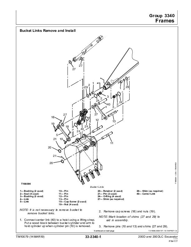
Bucket Links Remove and Install
Arm Remove and Install
Boom Remove and Install
Inspect Pins, Bushings and Bosses—Front Attachment
Bushings and Seal Remove and Install
Group 3360: Hydraulic System
Apply Vacuum to Hydraulic Oil Tank
Hydraulic Oil Cleanup Procedure Using Portable Filter Caddy
Pump 1 and 2 Remove and Install
Pump 1 and 2 Disassemble and Assemble
Pump 1 and 2 Inspection
Pump 1 and 2 Start-Up Procedure
Pump 1 and 2 Regulator Remove and Install
Pump 1 and 2 Regulator Disassemble and Assemble
Pilot Pump Remove and Install
Pilot Pump Disassemble and Assemble
Pilot Pump Drive Shaft Remove and Install
Pilot Pressure Regulating Valve and Filter Remove and Install
Pilot Pressure Regulating Valve and Filter Disassemble and Assemble
Pilot Shutoff Solenoid Valve Remove and Install
Pilot Shutoff Solenoid Valve Disassemble and Assemble
Fan Drive Pump Remove and Install
Fan Drive Motor Remove and Install
Fan Drive Control Valve Remove and Install
Solenoid Valve Manifold Remove and Install
Solenoid Valve Remove and Install—Power Dig (SG), Travel Speed (SI), Boom Mode (SC), and Boom Flow Rate (SF)
Pilot Valve (Left and Right) Remove and Install
Pilot Valve (Left and Right) Disassemble and Assemble
Travel Pilot Valve Remove and Install
Travel Pilot Valve Disassemble and Assemble
Pilot Signal Manifold Remove and Install
Pilot Signal Manifold Disassemble and Assemble
Control Valve Remove and Install
Control Valve (5-Spool) Disassemble and Assemble
Control Valve (4-Spool) Disassemble and Assemble
Hydraulic Oil Tank Remove and Install
Hydraulic Oil Tank Disassemble and Assemble
Restriction Valve Remove and Install
Hydraulic Oil Cooler Bypass Valve Remove and Install
Boom Cylinder Remove and Install
Boom Cylinder Disassemble and Assemble
Arm Cylinder Remove and Install
Arm Cylinder Disassemble and Assemble
Bucket Cylinder Remove and Install
Bucket Cylinder Disassemble and Assemble
Hydraulic Cylinder Bleed Procedure
Section 43: Swing or Pivoting System
Group 4350: Mechanical Drive Elements
Swing Gearbox Remove and Install
Swing Gearbox Disassemble and Assemble
Swing Gearbox Start-Up Procedure
Upperstructure Remove And Install
Swing Bearing Remove and Install
Swing Bearing Disassemble and Assemble
Swing Bearing Upper Seal Install
Swing Bearing Lower Seal Install
Group 4360: Hydraulic System
Center Joint Remove and Install
Center Joint Disassemble and Assemble
Center Joint Air Test
Swing Motor and Park Brake Remove and Install
Swing Motor and Park Brake Disassemble
Swing Motor and Park Brake Inspection
Swing Motor and Park Brake Assemble
Swing Motor and Park Brake Start-Up Procedure
Crossover Relief Valve and Make-Up Check Valve Remove and Install
Make-Up Check Valve Disassemble and Assemble
Swing Park Brake Release Valve Remove and Install
Section 99: Dealer Fabricated Tools
Group 9900: Dealer Fabricated Tools
DF1063 Lift Bracket
ST4920 Track Recoil Spring Disassembly and Assembly Tool
DFT1087 Track Recoil Spring Disassembly and Assembly Guard Tool
DFT1110 Spacer
DFT1130 Adapter
DFT1036A Travel Gearbox Nut Wrench
DF1038 Torque Adapter
DFT1109 Holding Bar
Center Joint (Rotary Manifold) Lifting Tool
DFT1144 Guide Pin
DFT1119 Pump Support
DFT1220 Swing Gearbox Nut Spanner Wrench
John Deere Excavators 200D, 200DLC Technical Service Repair Manual (TM10079)


