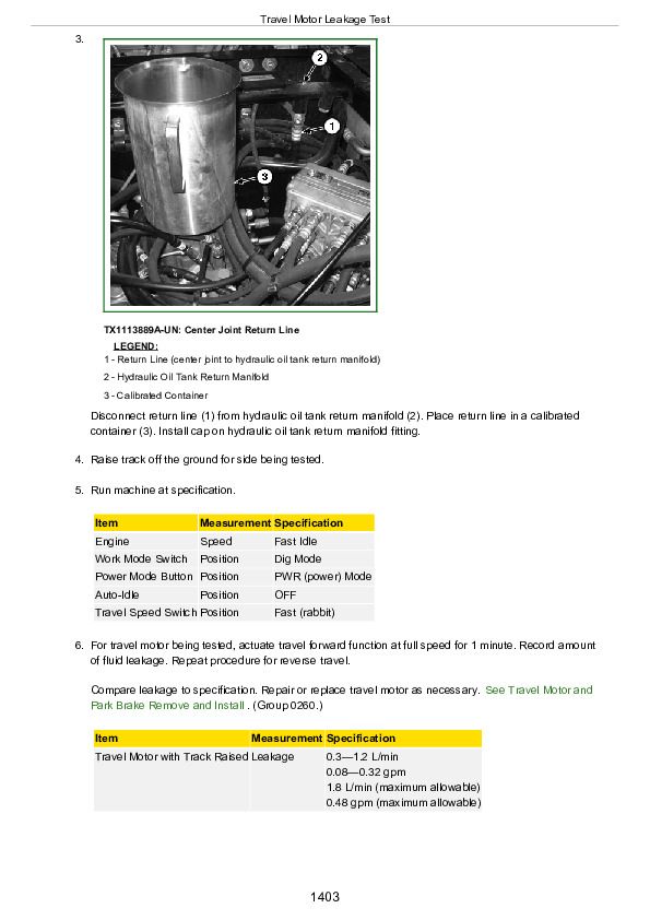
John Deere 135G Excavator Operation & Test Technical Service Manual (TM12666)
Catalog:
Model:
Complete workshop Operation Test technical manual with electrical wiring diagrams for John Deere 135G Excavator. It's the same service manual used by dealers that guaranteed to be fully functional and intact without any missing page.
John Deere 135G Excavator workshop service & repair manual includes:
* Numbered table of contents easy to use so that you can find the information you need fast.
* Detailed sub-steps expand on repair procedure information
* Numbered instructions guide you through every repair procedure step by step.
* Troubleshooting and electrical service procedures are combined with detailed wiring diagrams for ease of use.
* Notes, cautions and warnings throughout each chapter pinpoint critical information.
* Bold figure number help you quickly match illustrations with instructions.
* Detailed illustrations, drawings and photos guide you through every procedure.
* Enlarged inset helps you identify and examine parts in detail.
TM12666 - John Deere 135G Excavator Operation & Test Technical Manual.pdf
tm12667 - John Deere Excavatrice 135G.pdf
tm12668 - John Deere Excavadora 135G.pdf
Total Pages: 1,501 pages
File Format: PDF (bookmarked, Searchable, Printable, high quality)
Category: Operation and Test
Language: English Spanish French
Covered models: John Deere - Excavator - 1FF135GX__E400001(iT4)
MAIN SECTIONS
Foreword
Technical Information Feedback Form
General Information
Safety
Diagnostics
Main Controller (MCZ) Diagnostic Trouble Codes
Engine Control Unit (ECU) Diagnostic Trouble Codes
Monitor Controller (DSZ) Diagnostic Trouble Codes
Air Conditioner Controller (ACF) Diagnostic Trouble Codes
Operational Checkout Procedure
Operational Checkout Procedure
Engine
Theory of Operation
Diagnostic Information
Adjustments
Tests
Electrical System
System Information
System Diagrams
Sub-System Diagnostics
Monitor Operation
References
Power Train
Theory of Operation
Diagnostic Information
Hydraulic System
Theory of Operation
Diagnostic Information
Tests
Heating and Air Conditioning
Theory of Operation
Diagnostic Information
Tests
Dealer Fabricated Tools
tm12666 - 135G Excavator
Table of Contents
Foreword
Manual Identification—READ THIS FIRST!
Section 9000: General Information
Group 01: Safety
Recognize Safety Information
Follow Safety Instructions
Operate Only If Qualified
Wear Protective Equipment
Avoid Unauthorized Machine Modifications
Control Pattern Selector—If Equipped
Add Cab Guarding for Special Uses
Inspect Machine
Stay Clear of Moving Parts
Avoid High-Pressure Fluids
Avoid High-Pressure Oils
Work In Ventilated Area
Prevent Fires
Prevent Battery Explosions
Handle Chemical Products Safely
Decommissioning — Proper Recycling and Disposal of Fluids and Components
Exhaust Filter Ash Handling and Disposal
Prepare for Emergencies
Clean Debris from Machine
Use Steps and Handholds Correctly
Start Only From Operator's Seat
Use and Maintain Seat Belt
Prevent Unintended Machine Movement
Avoid Work Site Hazards
Keep Riders Off Machine
Avoid Backover Accidents
Inspect and Maintain ROPS
Avoid Machine Tip Over
Use Special Care When Lifting Objects
Add and Operate Attachments Safely
Park and Prepare for Service Safely
Service Cooling System Safely
Remove Paint Before Welding or Heating
Make Welding Repairs Safely
Drive Metal Pins Safely
Clean Exhaust Filter Safely
Section 9001: Diagnostics
Group 10: Main Controller (MCZ) Diagnostic Trouble Codes
Main Controller (MCZ) Diagnostic Trouble Codes
Controller Area Network 0 (CAN 0) Circuit Diagnostics
Controller Area Network 1 (CAN 1) Circuit Diagnostics
Interface Controller Area Network (N-CAN) Diagnostics
011000.02 - Abnormal EEPROM
011001.02 - Abnormal RAM
011002.02 - Abnormal A/D Converter
011003.03 - Abnormal Sensor Voltage
011006.02 - Engine Controller Communication Error
011007.02 - (CAN 0) Data Converter Communication Error 1
011008.02 - (CAN 1) Data Converter Communication Error 2
011009.02 - (CAN 0) Monitor Controller Communication Error 1
011010.02 - (CAN 1) Monitor Controller Communication Error 2
011100.02 - Abnormal Engine Speed
011101.03 - Engine Control Dial Sensor Circuit High Input
011101.04 - Engine Control Dial Sensor Circuit Low Input
011200.03 - Pump 1 Delivery Pressure Sensor Circuit High Input
011200.04 - Pump 1 Delivery Pressure Sensor Circuit Low Input
011202.03 - Pump 2 Delivery Pressure Sensor Circuit High Input
011202.04 - Pump 2 Delivery Pressure Sensor Circuit Low Input
011206.03 - Pump 1 Flow Control Pressure Sensor Circuit High Input
011206.04 - Pump 1 Flow Control Pressure Sensor Circuit Low Input
011208.03 - Pump 2 Flow Control Pressure Sensor Circuit High Input
011208.04 - Pump 2 Flow Control Pressure Sensor Circuit Low Input
011301.03 - Swing Pilot Pressure Sensor Circuit High Input
011301.04 - Swing Pilot Pressure Sensor Circuit Low Input
011302.03 - Boom Up Pilot Pressure Sensor Circuit High Input
011302.04 - Boom Up Pilot Pressure Sensor Circuit Low Input
011303.03 - Arm In Pilot Pressure Sensor Circuit High Input
011303.04 - Arm In Pilot Pressure Sensor Circuit Low Input
011304.03 - Travel Pilot Pressure Sensor Circuit High Input
011304.04 - Travel Pilot Pressure Sensor Circuit Low Input
011307.03 - Front Attachment Pilot Pressure Sensor Circuit High Input
011307.04 - Front Attachment Pilot Pressure Sensor Circuit Low Input
011400.02 - Pump 2 Flow Rate Limit Solenoid Valve Abnormal Feedback
011400.03 - Pump 2 Flow Rate Limit Solenoid Valve Feedback High Current
011400.04 - Pump 2 Flow Rate Limit Solenoid Valve Feedback Low Current
011401.02 - Torque Control Solenoid Valve Abnormal Feedback
011401.03 - Torque Control Solenoid Valve Feedback High Current
011401.04 - Torque Control Solenoid Valve Feedback Low Current
011402.02 - 4-Spool Solenoid Valve Unit (SF) Abnormal Feedback
011402.03 - 4-Spool Solenoid Valve Unit (SF) Feedback High Input
011402.04 - 4-Spool Solenoid Valve Unit (SF) Feedback Low Input
011403.02 - 4-Spool Solenoid Valve Unit (SC) Abnormal Feedback
011403.03 - 4-Spool Solenoid Valve Unit (SC) Feedback High Input
011403.04 - 4-Spool Solenoid Valve Unit (SC) Feedback Low Input
011407.02 - 4-Spool Solenoid Valve Unit (SG) Abnormal Feedback
011407.03 - 4-Spool Solenoid Valve Unit (SG) Feedback High Input
011407.04 - 4-Spool Solenoid Valve Unit (SG) Feedback Low Input
011408.02 - 2-Spool Solenoid Valve Unit (SJ) Abnormal Feedback
011408.03 - 2-Spool Solenoid Valve Unit (SJ) Feedback High Input
011408.04 - 2-Spool Solenoid Valve Unit (SJ) Feedback Low Input
011409.02 - 2-Spool Solenoid Valve Unit (SZ) Abnormal Feedback
011409.03 - 2-Spool Solenoid Valve Unit (SZ) Feedback High Input
011409.04 - 2-Spool Solenoid Valve Unit (SZ) Feedback Low Input
011410.02 - Pump 1 Flow Rate Limit Solenoid Feedback Current Abnormal
011410.03 - Pump 1 Flow Rate Limit Solenoid Feedback Current High
011410.04 - Pump 1 Flow Rate Limit Solenoid Feedback Current Low
011428.02 - 4-Spool Solenoid Valve Unit (SD) Abnormal Feedback
011428.03 - 4-Spool Solenoid Valve Unit (SD) Feedback High Input
011428.04 - 4-Spool Solenoid Valve Unit (SD) Feedback Low Input
011434.02 - Attachment Relief 1 (Upper) Proportional Solenoid Valve Abnormal Feedback
011434.03 - Attachment Relief 1 (Upper) Proportional Solenoid Valve Feedback High Current
011434.04 - Attachment Relief 1 (Upper) Proportional Solenoid Valve Feedback Low Current
011435.02 - Attachment Relief 2 (Lower) Proportional Solenoid Valve Abnormal Feedback
011435.03 - Attachment Relief 2 (Lower) Proportional Solenoid Valve Feedback High Current
011435.04 - Attachment Relief 2 (Lower) Proportional Solenoid Valve Feedback Low Current
011436.02 - Breaker Relief Proportional Solenoid Valve Abnormal Feedback
011436.03 - Breaker Relief Proportional Solenoid Valve Feedback High Current
011436.04 - Breaker Relief Proportional Solenoid Valve Feedback Low Current
011457.02 - 2-Speed Activation Solenoid Disconnected or Not Present
011458.02 - (Auxiliary) Discontinuity of Selector Valve
011459.02 - Idle Stop Relay Circuit Malfunction
011810.03 - Electric Lever Operating Pressure Sensor 1 High Voltage
011810.04 - Electric Lever Operating Pressure Sensor 1 Low Voltage
011812.02 - OPT Electric Lever 1 Neutral Abnormal
011813.02 - OPT Electric Lever 1 Abnormal Operation
011816.02 - OPT Solenoid 1 Feedback Abnormal
011816.03 - OPT Solenoid 1 Feedback Current High
011816.04 - OPT Solenoid 1 Feedback Current Low
011817.02 - OPT Solenoid 2 Feedback Abnormal
011817.03 - OPT Solenoid 2 Feedback Current High
011817.04 - OPT Solenoid 2 Feedback Current Low
011901.03 - Hydraulic Oil Temperature Sensor Circuit High Input
011901.04 - Hydraulic Oil Temperature Sensor Circuit Low Input
015011.03 - Hydraulic Oil Temperature Sensor Circuit High Input (Pilot)
015011.04 - Hydraulic Oil Temperature Sensor Circuit Low Input (Pilot)
015016.03 - Right Analog Stroke Sensor Circuit High Input
015016.04 - Right Analog Stroke Sensor Circuit Low Input
020010.02 - Exhaust Filter Alarm
020011.02 - Electric Lever Alarm
020012.02 - Line Filter Restriction Alarm
020303.02 - Electric Lever Pilot Cut Alarm
Group 20: Engine Control Unit (ECU) Diagnostic Trouble Codes
Engine Control Unit (ECU) Diagnostic Trouble Codes
000081.00 - High Exhaust Filter Differential Pressure (P2453)
000081.01 - Low Exhaust Filter Differential Pressure (P2452)
000081.02 - Zero-Point Calibration of Exhaust Filter Differential Pressure Sensor is Abnormal (P2456)
000081.03 - Exhaust Filter Differential Pressure Sensor Circuit High Input (P2455)
000081.04 - Exhaust Filter Differential Pressure Sensor Circuit Low Input (P2454)
000091.02 - Accelerator Pedal Position Sensor 1-2 Correlation (P2138)
000091.03 - Accelerator Pedal Position Sensor 1 High Input (P2123)
000091.03 - Accelerator Pedal Position Sensor 2 High Input (P2128)
000091.04 - Accelerator Pedal Position Sensor 1 Low Input (P2122)
000091.04 - Accelerator Pedal Position Sensor 2 Low Input (P2127)
000100.03 - Engine Oil Pressure Sensor Circuit High Input (P0523)
000100.04 - Engine Oil Pressure Sensor Circuit Low Input (P0522)
000102.00 - Over Boost-Pressure (P0234)
000102.00 - Over Boost-Pressure (P0234)
000102.01 - Declined Boost Pressure (P0299)
000102.03 - Boost Pressure Sensor Circuit High Input (P0238)
000102.04 - Boost Pressure Sensor Circuit Low Input (P0237)
000105.03 - Boost Temperature Sensor Circuit High Input (P1113)
000105.04 - Boost Temperature Sensor Circuit Low Input (P1112)
000108.03 - Atmospheric Pressure Sensor Circuit High Input (P2229)
000108.04 - Atmospheric Pressure Sensor Circuit Low Input (P2228)
000110.00 - Overheat (P0217)
000110.03 - Engine Coolant Temperature Circuit High Input (P0118)
000110.04 - Engine Coolant Temperature Circuit Low Input (P0117)
000132.03 - Air Flow Sensor Circuit High Input (P0103)
000132.04 - Air Flow Sensor Circuit Low Input (P0102)
000157.00 - Pressure Increase in Common Rail (Secondary) (P0088)
000157.03 - Common Rail Pressure Sensor Circuit High Input (P0193)
000157.04 - Common Rail Pressure Sensor Circuit Low Input (P0192)
000157.15 - Abnormal Common Rail Pressure (Over Pumping) (P0089)
000157.16 - Pressure Increase in Common Rail (Primary) (P0088)
000158.03 - Abnormally High Battery System Voltage (P0563)
000172.03 - Intake Air Temperature Sensor Circuit High Input (P0113)
000172.04 - Intake Air Temperature Sensor Circuit Low Input (P0112)
000173.00 - Abnormally High Exhaust Temperature Sensor 1 (DPF Inlet) (P0426)
000173.03 - Exhaust Temperature Sensor 1 Circuit High Input (DPF Inlet) (P0428)
000173.04 - Exhaust Temperature Sensor 1 Circuit Low Input (DPF Inlet) (P0427)
000174.03 - Combustion Temperature Sensor Circuit High Input (P0183)
000174.04 - Combustion Temperature Sensor Circuit Low Input (P0182)
000190.00 - Engine Overrun (P0219)
000628.02 - Abnormal ROM (P0601)
000633.07 - Common Rail Pressure Limiter Open (P0087)
000636.02 - Abnormal Cam Angle Sensor (No Signal) (P0340)
000636.07 - Phase Difference Between Cam and Sensor (P0016)
000639.02 - Abnormal CAN Time-Out (U0101)
000639.19 - Abnormal CAN Bus (U0073)
000651.05 - Cylinder 1 Injector Circuit Open (P0201)
000652.05 - Cylinder 2 Injector Circuit Open (P0202)
000653.05 - Cylinder 3 Injector Circuit Open (P0203)
000654.05 - Cylinder 4 Injector Circuit Open (P0204)
000723.02 - Crank Position Sensor Failure (No Signal) (P0335)
000723.02 - Crank Position Sensor Failure (Abnormal Signal) (P0336)
001077.02 - Abnormal CPU (P0606)
001079.02 - Abnormal 5V-Electric Power Circuit #1 (P0641)
001080.02 - Abnormal 5V-Electric Power Circuit #2 (P0651)
001131.03 - Manifold Temperature Sensor Circuit High Input (P041C)
001131.04 - Manifold Temperature Sensor Circuit Low Input (P041D)
001239.01 - Pressure Decline in Common Rail (No Pumping Pressure) (P0093)
001239.17 - Pressure Decline in Common Rail (Lack of Pumping Pressure) (P1093)
001347.03 - SCV Drive Circuit + Short Circuit B (P0092)
001347.04 - SCV Drive Circuit Open or Short Circuited to GND (P0091)
001381.03 - Fuel Filter Restriction Sensor Circuit High Input (P1294)
001381.04 - Fuel Filter Restriction Sensor Circuit Low Input (P1293)
001485.05 - Abnormal Main Relay Circuit (Inactivation) (P0685)
001485.06 - Abnormal Main Relay Circuit (Kept Closed) (P0687)
010001.02 - EGR Position Error (Brushless Type) (P0409)
010001.13 - Abnormal EGR Zero-Point Calibration (P1404)
010002.02 - Abnormal EGR Valve Control Circuit (P0404)
010003.02 - Abnormal Injector Common 1 Circuit (P2146)
010004.02 - Abnormal Injector Common 2 Circuit (P2149)
010005.01 - Abnormal Charge Circuit (Bank 1) (P1261)
010006.01 - Abnormal Charge Circuit (Bank 2) (P1262)
010007.02 - Abnormal CPU Monitor IC (P0606)
010008.02 - Abnormal A/D Converter (P060B)
010009.02 - Abnormal 5V-Electric Power Circuit #3 (P0697)
010010.02 - Abnormal 5V-Electric Power Circuit #4 (P1655)
010012.02 - Abnormal 12V Circuit (P0560)
010013.02 - Abnormal EEPROM/Abnormal HDEEPROM (P1621)
010022.02 - Abnormal Intake Throttle Control Circuit (P0638)
010022.03 - Intake Throttle Position Sensor Circuit High Input (P0123)
010022.04 - Intake Throttle Position Sensor Circuit Low Input (P0122)
010023.03 - EVRV Vacuum Sensor High Input (P2528)
010023.04 - EVRV Vacuum Sensor Low Input (P2527)
010023.20 - Abnormal Turbo EVRV (P0045)
010024.03 - Exhaust Temperature Sensor 2 Circuit High Input (DOC Inlet) (P042D)
010024.04 - Exhaust Temperature Sensor 2 Circuit Low Input (DOC Inlet) (P042C)
010025.05 - Exhaust Filter Light Failure (P1669)
010026.00 - Exhaust Filter PM Over-Restriction 2 (P1455)
010026.15 - Exhaust Filter PM Over-Restriction (P242F)
010027.00 - Exhaust Filter Cleaning Decision Error (P1471)
010028.00 - Abnormally High Exhaust Temperature Sensor 2 (DOC Outlet) (P042B)
010029.00 - Over Frequent Exhaust Filter Regeneration Time-Out (P2458)
010032.02 - QR Code Error (P0602)
010033.02 - Abnormal RAM (P0604)
010040.19 - Abnormal ISO-CAN Bus (U0001)
Group 30: Monitor Controller (DSZ) Diagnostic Trouble Codes
Monitor Controller (DSZ) Diagnostic Trouble Codes
013002.02 - ECU Communication Error
013003.02 - Main Controller (MCZ) Communication Error 1
013004.02 - Main Controller (MCZ) Communication Error 2
013005.02 - Monitor Controller (DSZ) Communication Error 1
013006.02 - Monitor Controller (DSZ) Communication Error 2
013007.02 - Machine Controller (BCZ) Communication Error
020113.02 - System Error Alarm
Group 40: Information Controller (ICZ) Diagnostic Trouble Codes
Information Controller (ICZ) Diagnostic Trouble Codes
013334.02 - Radiator Coolant Error
014001.02 - Flash Memory Read/Write Error
014002.02 - External RAM Read/Write Error
014003.02 - Abnormal EEPROM
014006.02 - Communication Terminal:Communication Error
014008.02 - Abnormal Internal RAM
014021.02 - Communication Terminal Security Error
014022.02 - SIM Card Error
014023.02 - Security Error
020100.02 - Overheat Alarm
020101.02 - Engine Warning Alarm
020102.02 - Engine Oil Pressure Alarm
020105.02 - Hydraulic Oil Filter Restriction Alarm
020106.02 - Air Cleaner Restriction Alarm
020109.02 - Pilot Control Shut-Off Lever Alarm
020110.02 - Fuel Filter Restriction Alarm
020114.02 - Overheat Alarm
020133.02 - Crane Function Alarm
020137.02 - Exhaust Filter Alarm
020141.02 - Exhaust Temperature Alarm
020142.02 - Intake Air Temperature Alarm
020145.02 - Boost Temperature Increase Alarm
020146.02 - Fuel Temperature Increase Alarm
020149.02 - EGR Gas Temperature Alarm
Group 50: Air Conditioner Controller (ACF) Diagnostic Trouble Codes
Air Conditioner Controller (ACF) Diagnostic Trouble Codes
11 - Open Circuit in Air Recirculation Sensor
12 - Short-Circuited Air Recirculation Sensor
13 - Open Circuit in Ambient Air Temperature Sensor
14 - Short-Circuited Ambient Air Temperature Sensor
18 - Short-Circuited Solar Radiation Sensor
21 - Open Circuit in Air Conditioner Freeze Control Switch
22 - Short-Circuited Air Conditioner Freeze Control Switch
43 - Abnormal Air Conditioner and Heater Blower Port Change Servomotor
44 - Abnormal Air Conditioner and Heater Mixer Servomotor
51 - Abnormal High/Low Refrigerant Pressure
91 - Communication Error
92 - CAN Bus Off Error
Section 9005: Operational Checkout Procedure
Group 10: Operational Checkout Procedure
Operational Checkout
Section 9010: Engine
Group 05: Theory of Operation
Isuzu Engine
Engine Fuel System Component Location
Engine Cooling System Component Location
Cold Weather Starting Aid
Engine Speed Control System Operation
Group 15: Diagnostic Information
Isuzu Engine
Group 20: Adjustments
Isuzu Engine
Group 25: Tests
Isuzu Engine
Section 9015: Electrical System
Group 05: System Information
Electrical Diagram Information
Group 10: System Diagrams
Explanation of Wire Markings
Fuse and Relay Specifications
System Functional Schematic, Component Location, and Wiring Diagram Master Legend
System Functional Schematic
Cab Harness (W1) Component Location
Cab Harness (W1) Wiring Diagram
Machine Harness (W2) Component Location
Machine Harness (W2) Wiring Diagram
Monitor Harness (W3) Component Location
Monitor Harness (W3) Wiring Diagram
Engine Harness (W4) Component Location
Engine Harness (W4) Wiring Diagram
Pump Harness (W8) Component Location
Pump Harness (W8) Wiring Diagram
Exhaust Filter Parked Cleaning Switch Harness (W9) Component Location
Exhaust Filter Parked Cleaning Switch Harness (W9) Wiring Diagram
Pilot Shutoff Switch Harness (W11) Component Location
Pilot Shutoff Switch Harness (W11) Wiring Diagram
Auxiliary Fuse Box Harness (W13) Component Location
Auxiliary Fuse Box Harness (W13) Wiring Diagram
Heated Air Seat Harness (W14) Component Location
Heated Air Seat Harness (W14) Wiring Diagram
Multi-Function Pilot Control Lever Harness (W15) Component Location
Multi-Function Pilot Control Lever Harness (W15) Wiring Diagram
Travel Alarm Cancel Switch Harness (W16) Component Location
Travel Alarm Cancel Switch Harness (W16) Wiring Diagram
Attachment Harness (W17) Component Location
Attachment Harness (W17) Wiring Diagram
Rear Camera Harness (W19) Component Location
Rear Camera Harness (W19) Wiring Diagram
9-Pin Service ADVISOR™ Connector (W20) Component Location
9-Pin Service ADVISOR™ Connector (W20) Wiring Diagram
Pilot Shutoff Valve Harness (W21) Component Location
Pilot Shutoff Valve Harness (W21) Wiring Diagram
Auxiliary 3-Button Cancel Switch Harness (W22) Component Location
Auxiliary 3-Button Cancel Switch Harness (W22) Wiring Diagram
Seat Heater Switch Harness (W24) Component Location
Seat Heater Switch Harness (W24) Wiring Diagram
Travel Alarm Harness (W26) Component Location
Travel Alarm Harness (W26) Wiring Diagram
Travel Sub Harness (W27) Component Location
Travel Sub Harness (W27) Wiring Diagram
Starter Switch Harness (W29) Component Location
Starter Switch Harness (W29) Wiring Diagram
Data Converter Harness (W30) Component Location
Data Converter Harness (W30) Wiring Diagram
Data Converter Interface Harness (W31) Component Location
Data Converter Interface Harness (W31) Wiring Diagram
2-Speed Harness (W32) Component Location
2-Speed Harness (W32) Wiring Diagram
Heater and Air Conditioner Harness (W41) Component Location
Heater and Air Conditioner Harness (W41) Wiring Diagram
Auxiliary Solenoid Harness (W61) Component Location
Auxiliary Solenoid Harness (W61) Wiring Diagram
Auxiliary Function Lever (AFL) Harness (W75) Component Location
Auxiliary Function Lever (AFL) Harness (W75) Wiring Diagram
Auxiliary Function Lever (AFL) Solenoid Harness (W76) Component Location
Auxiliary Function Lever (AFL) Solenoid Harness (W76) Wiring Diagram
Auxiliary Function Lever (AFL) Grip Harness (W77) Component Location
Auxiliary Function Lever (AFL) Grip Harness (W77) Wiring Diagram
Auxiliary Function Enable Switch Harness (W78) Component Location
Auxiliary Function Enable Switch Harness (W78) Wiring Diagram
Satellite (SAT) Harness (W6003) Component Location
Satellite (SAT) Harness (W6003) Wiring Diagram
JDLink™ Harness (W6004) Component Location
JDLink™ Harness (W6004) Wiring Diagram
Group 15: Sub-System Diagnostics
Controller Area Network (CAN) Theory of Operation
Starting and Charging Circuit Theory of Operation
Monitor Controller (DSZ) Circuit Theory of Operation
Engine Control Unit (ECU) Circuit Theory of Operation
Exhaust Aftertreatment Circuit Theory of Operation
Main Controller (MCZ) Circuit Theory of Operation
Travel Alarm Circuit Theory of Operation
Machine Controller (BCZ) Circuit Theory of Operation
Windshield Wiper and Washer Circuit Theory of Operation
Lighting Circuit Theory of Operation
Pilot Shutoff Circuit Theory of Operation
Attachment Control Circuit Theory of Operation
Group 16: Monitor Operation
Service Menu
Troubleshooting
Monitoring
Controller Version
Issued Warning Record
Operation
Machine Setting
Monitor Setting
Engine Setting
Exhaust Filter No.
Group 20: References
Reading Diagnostic Trouble Codes with Monitor Display
Service ADVISOR™ Diagnostic Application
Service ADVISOR™ Connection Procedure
Reading Diagnostic Trouble Codes with Service ADVISOR™ Diagnostic Application
Clearing Engine Diagnostic Trouble Codes
MPDr Application
MPDr Connection Procedure
Fuse Test
Relay Test
Glow Plug Relay Test
Pressure Sensor Test
Solenoid Test
Proportional Solenoid Test
Temperature Sensor Test
Alternator Test
Electrical Component Checks
Battery Remove and Install
Rear Cover Remove and Install
Main Controller (MCZ) Remove and Install
Machine Controller (BCZ) Remove and Install
Engine Control Unit (ECU) Remove and Install
Exhaust Differential Pressure Sensor Zero Point Calibration
Ash Reset
No Load Max
Data Converter Remove and Install
Monitor Controller (DSZ) Remove and Install
Air Conditioner Controller (ACF) Remove and Install
Key Switch Remove and Install
Right Switch Console Remove and Install
Left Switch Console Remove and Install
Travel Alarm Remove and Install
Heater Control Disable and Enable
Disconnect Tab Retainer Connectors
Disconnecting Spring Wire Clip Connectors
Replace DEUTSCH™ Connectors
Replace DEUTSCH™ Rectangular or Triangular Connectors
Install DEUTSCH™ Contact
Replace WEATHER PACK™ Connector
Install WEATHER PACK™ Contact
Replace (Pull Type) Metri-Pack™ Connectors
Replace (Push Type) Metri-Pack™ Connectors
Replace CINCH™ Connectors
Install CINCH™ Contact
Repair 32 and 48 Way CINCH™ Connectors
Remove Connector Body from Blade Terminals
Section 9020: Power Train
Group 05: Theory of Operation
Track Adjuster and Recoil Spring Operation
Travel Gear Case Operation
Group 15: Diagnostic Information
Noisy or Loose Track Chain
Tight Track Chain
Frequent Track Chain Sag Adjustment Required
Excessive Oil Leakage From Front Idler, Track Rollers, or Carrier Rollers
Bent Track Shoes
“Popping” of Track
Cracked Track Link
Chipped Link Rails
Individual Undercarriage Component Wear
Measure Swing Bearing Wear
Section 9025: Hydraulic System
Group 05: Theory of Operation
Hydraulic System Operation
Pilot System Operation
Pilot Pump, Pressure Regulating Valve and Filter Operation
Pilot Shutoff Solenoid Valve Operation
Pilot Control Valve Operation
Travel Pilot Control Valve Operation
Pilot Operation of Control Valve Operation
Pilot Signal Manifold Operation
Pump 1, Pump 2, and Drive Gear Case Operation
Pump 1 and Pump 2 Regulator Operation
Engine Speed Sensing Control Circuit Operation
Control Valve Operation
Control Valve Check Valves Identification and Operation
Main Relief Valve Circuit Operation
Circuit Relief and Anticavitation Valve Operation
Travel Flow Combiner Valve Operation
Auxiliary Flow Combiner Valve and Bypass Shutoff Valve Operation
Boom Lower Meter-In Cut Valve Operation
Boom Regenerative Valve Circuit Operation
Dig Regenerative Valve Circuit Operation
Arm Regenerative Valve Circuit Operation
Bucket Regenerative Valve Circuit Operation
Boom and Arm Reduced Leakage Valves Operation
Arm 1 Flow Rate Control Valve Circuit Operation
Arm 2 Flow Rate Control Valve Circuit Operation
Bucket Flow Rate Control Valve Circuit Operation
Boom Flow Rate Control Valve Circuit Operation
Auxiliary Flow Rate Control Valve Circuit Operation
Blade Circuit Operation—If Equipped
Swing Reduction Gear Case Operation
Swing Motor, Crossover Relief Valve, and Make-Up Check Valve Operation
Swing Motor Park Brake Release Circuit Operation
Center Joint Operation
Travel Motor and Park Brake Valve Operation
Travel Motor Speed Circuit Operation
Diesel Particulate Filter (DPF) Burn Solenoid Valves
Cylinder Operation
Return Filter Operation
Auxiliary System Operation
Auxiliary Pilot Control Valve Operation
Flow Rate Select Solenoid Valve Operation
Flow Rate Pressure Reducing Valve Operation
Auxiliary Shuttle Valve Operation
Auxiliary High Flow Line Kit Operation
Two Way Solenoid Kit Operation
Two Pump Combined Flow Kit Operation
Group 15: Diagnostic Information
All Hydraulic Functions Slow
Hydraulic Oil Overheats
No Hydraulic Functions
Poor Combined Operation
All Functions Cannot Be Operated
Function Does Not Stop When Control Lever Released
Some Functions Cannot Be Operated, All Others Are Normal
All Functions Slow
Functions Move in Opposite Direction
All Dig Functions Slow or No Power
Some Dig Functions Slow (Not All)
Load Drifts Down When Control Lever is in Neutral Position
Load Falls When Control Valve is Actuated To Raise Load With Engine Running at Slow Idle
H-P (High Power) Function Does Not Operate, PWR (Power) Mode is Normal
Swing Speed Slow in Both Directions
Swing Speed Slow or Does Not Operate in One Direction
Upperstructure Drift with Swing Valve in Neutral
Swing Function Does Not Operate
Travel Park Brakes Do Not Apply
Track Will Not Move in One Direction
Track Will Not Move in Either Direction
Machine Mistracks at All Speeds in Both Directions
Slow Travel Speed or Low Power
Combined Travel and Dig Functions Slow or No Power
Travel is "Jerky "
Machine Will Not Hold Back and Park Brakes Engage and Disengage When Traveling Down an Incline
Machine Will Not Turn Smoothly in One Direction or Park Brake Grabs
Pump 1, Pump 2, and Pilot Pump Line Identification
Control Valve Line Identification
Swing Motor Line Identification
Pilot Control Valve-to-Pilot Signal Manifold Component Location—Excavator Pattern
Pilot Control Valve-to-Pilot Signal Manifold Component Location—Backhoe Pattern
Pilot Signal Manifold-to-Control Valve Line Connection
Travel System Component Location
Travel Hydraulic System Line Connection
Blade Hydraulic System Component Location
Auxiliary Attachment Schematic
Auxiliary System Line Connections
Hydraulic System Schematic
Hydraulic System Component Location
Hydraulic System Line Connections
Group 25: Tests
JT05800 Digital Thermometer Installation
JT02156A Digital Pressure and Temperature Analyzer Kit Installation
General Hydraulic Oil Cleanup Procedure
Hydraulic Component Failure Cleanup Procedure
Hydraulic Oil Tank Pressure Release Procedure
Hydraulic Oil Warm-Up Procedure
Pilot Pressure Regulating Valve Test and Adjustment
Control Valve Spool Actuating Pilot Pressure Test
Dig Regenerative Solenoid Valve Test and Adjustment
Arm Regenerative Solenoid Valve Test and Adjustment
Power Dig Solenoid Valve Test and Adjustment
Arm 2 Flow Control Solenoid Valve Test and Adjustment
Torque Control Solenoid Valve Test and Adjustment
Pump Control Pilot Pressure Signal Test
Main Relief and Power Dig Valve Test and Adjustment
Circuit Relief Valve Test and Adjustment
Blade Main Relief Valve Test and Adjustment
Swing Motor Crossover Relief Valve Test and Adjustment
Travel Motor Crossover Relief Valve Test and Adjustment
Pump Regulator Test and Adjustment—Minimum Flow
Pump Regulator Test and Adjustment—Maximum Flow
Pump Flow Test
Comprehensive Pump Flow Test
Swing Motor Leakage Test
Travel Motor Leakage Test
Cylinder Drift Test—Boom, Arm, and Bucket
Section 9031: Heating and Air Conditioning
Group 05: Theory of Operation
Air Conditioning System Cycle of Operation
Group 15: Diagnostic Information
Air Conditioning System Does Not Operate
No Air Flow From Heater and Air Conditioner Vents
Air Conditioning Does Not Cool Interior of Cab
Air Conditioning Runs Constantly, Too Cold
Interior Windows Continue to Fog Using Air Conditioner
Heater System Does Not Operate
Heater Does Not Warm Interior of Cab
Interior Windows Continue to Fog Using Heater
Heater and Air Conditioner Component Location
Group 25: Tests
Refrigerant Cautions and Proper Handling
Heater and Air Conditioner Operational Checks
Air Conditioner Compressor Clutch Test
Refrigerant Leak Test
Refrigerant Hoses and Tubing Inspection
Air Conditioner Compressor Belt Check
R134a Air Conditioning System Test
Operating Pressure Diagnostic Chart
Section 9900: Dealer Fabricated Tools
Group 99: Dealer Fabricated Tools
DFT1218 Split Flange Hose Cap
John Deere 135G Excavator Operation & Test Technical Service Manual (TM12666)


