John Deere 4WD Loaders 944K Hybrid Operation and Test Service Manual (TM13094X19)
Catalog:
Model:
Complete Operation and Test Service manual with Electrical Wiring Diagrams for John Deere 4WD Loaders 944K Hybrid (SN. from E669456) (PIN: 1DW944KX**E669456—), with workshop information to maintain, diagnose, and rebuild like professional mechanics.
John Deere 944K Hybrid Loaders 4WD workshop Operation and Test Service manual includes:
* Numbered table of contents easy to use so that you can find the information you need fast.
* Detailed sub-steps expand on repair procedure information
* Numbered instructions guide you through every repair procedure step by step.
* Troubleshooting and electrical service procedures are combined with detailed wiring diagrams for ease of use.
* Notes, cautions and warnings throughout each chapter pinpoint critical information.
* Bold figure number help you quickly match illustrations with instructions.
* Detailed illustrations, drawings and photos guide you through every procedure.
* Enlarged inset helps you identify and examine parts in detail.
TM13094X19 - John Deere 4WD Loaders 944K Hybrid (SN. from E669456) Technical Manual - Repair.PDF
TM13094X28 - John Deere 944K Chargeur à transmission 4 roues motrices.pdf
Total Pages: 3,163 pages
File Format: PDF (bookmarked, ToC, Searchable, Printable, high quality)
Language: English French
Category: Operation and Test
John Deere - 4WD Loader - 1DW944K_ _ _E669456–E690604
MAIN SECTIONS
Foreword
Manual Identification-READ THIS FIRST!
General Information
Safety Information
Diagnostics
Engine Control Unit (ECU) Diagnostic Trouble Codes
Transmission Control Unit (TCU) Diagnostic Trouble Codes
Vehicle Control Unit (VCU) Diagnostic Trouble Codes
Sealed Switch Module (OC3) Diagnostic Trouble Codes
Rear Object Detection (ROD) Diagnostic Trouble Codes
Tire Pressure Monitoring (TPM) Diagnostic Trouble Codes
Motor Inverter (MT1) Diagnostic Trouble Codes
Motor Inverter (MT2) Diagnostic Trouble Codes
Motor Inverter (MT3) Diagnostic Trouble Codes
Motor Inverter (MT4) Diagnostic Trouble Codes
Generator Inverter (GN1) Diagnostic Trouble Codes
Generator Inverter (GN2) Diagnostic Trouble Codes
Bucket Lever Controller (RJ1) Diagnostic Trouble Codes
Boom Lever Controller (RJ2) Diagnostic Trouble Codes
Primary Display Unit (PDU) Diagnostic Trouble Codes
Operational Checkout Procedure
Operational Checkout Procedure
Engine
Theory of Operation
System Diagrams
Diagnostic Information
Adjustments
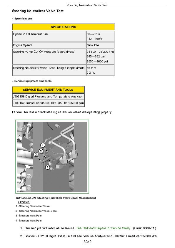
Tests
Electrical System
Theory of Operation
System Diagrams
Diagnostic Information
Monitor Operation
Diagnostic Test Box
Adjustments
Tests
Electric Drive System
Theory of Operation
System Diagrams
Diagnostic Information
Adjustments
Tests
Power Train
Theory of Operation
System Diagrams
Diagnostic Information
Adjustments
Tests
Pneumatic System
Theory of Operation
System Diagrams
Diagnostic Information
Tests
Hydraulic System
Theory of Operation
System Diagrams
Diagnostic Information
Adjustments
Tests
Heating and Air Conditioning
Theory of Operation
System Diagrams
Diagnostic Information
Tests
tm13094x19 - 944K Hybrid 4WD Loader
Table of Contents
Foreword
Manual Identification—READ THIS FIRST!
Section 9000: General Information
Group 01: Safety Information
Recognize Safety Information
Follow Safety Instructions
Operate Only If Qualified
Wear Protective Equipment
Avoid Unauthorized Machine Modifications
Inspect Machine
Stay Clear of Moving Parts
Avoid High-Pressure Fluids
Avoid High-Pressure Oils
Work In Ventilated Area
Avoid Static Electricity Risk When Refueling
Prevent Fires
In Case of Machine Fire
Prevent Battery Explosions
Handle Chemical Products Safely
Handle Starting Fluid Safely
Decommissioning — Proper Recycling and Disposal of Fluids and Components
Exhaust Filter Ash Handling and Disposal
Prepare for Emergencies
Clean Debris from Machine
Add Cab Guarding for Special Uses
Use Steps and Handholds Correctly
Start Only From Operator's Seat
Use and Maintain Seat Belt
Prevent Unintended Machine Movement
Avoid Work Site Hazards
Keep Riders Off Machine
Avoid Backover Accidents
Avoid Machine Tip Over
Operating on Slopes
Operating or Traveling On Public Roads
Use Special Care When Operating Loader
Inspect and Maintain ROPS
Keep the Operator Protective Structure (OPS) in Place
Travel Safely
Prevent Acid Burns
Add and Operate Attachments Safely
High-Altitude Operation
Park and Prepare for Service Safely
Prepare Electric Drive System for Service Safely
Avoid Pressure Washing Electric Drive Components
Service Cooling System Safely
Remove Paint Before Welding or Heating
Make Welding Repairs Safely
Drive Metal Pins Safely
Service Tires Safely
Clean Exhaust Filter Safely
Section 9001: Diagnostics
Group 10: Engine Control Unit (ECU) Diagnostic Trouble Codes
Engine Control Unit (ECU) Diagnostic Trouble Codes
000237.02 - Vehicle Identification Conflict
000237.13 - Vehicle Identification Fault
000237.31 - Communication Fault
001321.09 - Starter Signal Invalid
002795.31 - Turbocharger Actuator Fault
003353.31 - Alternator Output Fault
003510.03 - Sensor Supply 2 Circuit Fault
003510.04 - Sensor Supply 2 Circuit Fault
003511.03 - Sensor Supply 3 Circuit Fault
003511.04 - Sensor Supply 3 Circuit Fault
003587.05 - Ether Starting Aid Circuit Fault
003587.06 - Ether Starting Aid Circuit Fault
003711.14 - Exhaust Filter Inlet Temperature Low
003711.31 - Exhaust Filter Inlet Temperature Low
003719.14 - Exhaust Filter Extremely Restricted
004766.15 - DOC Outlet Temperature Very High
520629.31 - Engine Control Unit Programming Fault
Group 20: Transmission Control Unit (TCU) Diagnostic Trouble Codes
Transmission Control Unit (TCU) Diagnostic Trouble Codes
000177.00 - Gearbox Oil Temp Overtemp
000237.02 - Invalid VIN
000237.14 - VIN Options Not Learned
000237.31 - VIN Message Missing
000521.03 - Brake Pedal Short to Power
000521.04 - Brake Pedal Short to Ground
000578.00 - Axle Oil Temp Overtemp
000628.12 - Controller Not Programmed
000629.12 - Controller Reset
000639.12 - Communication System
000639.14 - Communication System
000880.03 - Brake Lights Short to Power
000880.05 - Brake Lights Open Circuit
000880.06 - Brake Lights Short to Ground
001231.12 - Communication System
001231.14 - Communication System
001235.12 - Communication System
001235.14 - Communication System
001503.11 - Armrest Position Undetermined
002000.09 - CAN Comm Lost For ECU
002033.09 - CAN Comm Lost For VCU
002160.09 - CAN Comm Lost For GN1
002161.09 - CAN Comm Lost For GN2
002162.09 - CAN Comm Lost For MT1
002163.09 - CAN Comm Lost For MT2
002164.09 - CAN Comm Lost For MT3
002165.09 - CAN Comm Lost For MT4
002873.04 - Engine Light Switch On Short to Ground
002873.18 - Engine Light Switch Off Short to Ground
003655.04 - Shift Up Button Short to Ground
003656.04 - Shift Down Button Short to Ground
516641.03 - Park Brake Valve Short to Power
516641.05 - Park Brake Valve Open Circuit
516641.06 - Park Brake Valve Short to Ground
516642.03 - Park Brake Valve Short to Power
516642.05 - Park Brake Valve Open Circuit
516642.06 - Park Brake Valve Short to Ground
516643.03 - Park Brake Valve Short to Power
516643.05 - Park Brake Valve Open Circuit
516643.06 - Park Brake Valve Short to Ground
516644.03 - Park Brake Valve Short to Power
516644.05 - Park Brake Valve Open Circuit
516644.06 - Park Brake Valve Short to Ground
516681.02 - Ref Torque Invalid
516682.02 - Ref Torque Invalid
520351.00 - GN1 IGBT Temp Overtemp
520537.04 - Quick Shift Short to Ground
520539.04 - FNR - R Short to Ground
520540.04 - FNR - F Short to Ground
520555.03 - Accel Pedal Short to Power
520555.04 - Accel Pedal Short to Ground
521041.00 - Generator Winding Temp Overtemp
521043.00 - Brake Res Temp Overtemp
521248.03 - Rear Park Brake Pressure Short to Power
521248.04 - Rear Park Brake Pressure Short to Ground
521256.03 - Front Park Brake Pressure Short to Power
521256.04 - Front Park Brake Pressure Short to Ground
521487.01 - DC Bus B Severe Isolation
521487.09 - DC Bus B Isolation Failure
521487.18 - DC Bus B Moderate Isolation
521839.01 - DC Bus A Severe Isolation
521839.09 - DC Bus A Isolation Failure
521839.18 - DC Bus A Moderate Isolation
521900.03 - Articulation Angle Sensor Short to Power
521900.04 - Articulation Angle Sensor Short to Ground
521900.13 - Articulation Angle Sensor Out of Calibration
521932.00 - MT1 IGBT Temp Overtemp
522003.04 - FNR - NR Short to Ground
522327.00 - Motor Winding Temp Overtemp
522382.03 - Backup Alarm Failure
522382.05 - Backup Alarm Open Circuit
522382.06 - Backup Alarm Short to Ground
522401.15 - Maximum Machine Speed Exceeded
522409.04 - FNR - NF Short to Ground
522409.05 - FNR Open Circuit
522409.12 - FNR Mult Inputs
522410.12 - Park Brake Pressure Mismatch
523380.31 - Drivetrain Temp Derate Active
523440.04 - Unswitched Power Low Voltage
523489.03 - Engine Compartment Light Short to Power
523489.05 - Engine Compartment Light Open Circuit
523489.06 - Engine Compartment Light Short to Ground
523837.01 - Rear Service Brake Pressure Low
523837.03 - Rear Service Brake Short to Power
523837.04 - Rear Service Brake Short to Ground
523840.01 - Front Service Brake Pressure Low
523840.03 - Front Service Brake Short to Power
523840.04 - Front Service Brake Open Circuit
523952.31 - Traction Control Disabled
524099.02 - WP1 Operation Fault
Group 30: Vehicle Control Unit (VCU) Diagnostic Trouble Codes
Vehicle Control Unit (VCU) Diagnostic Trouble Codes
000096.04 - Fuel Level Sensor Short to Ground
000096.05 - Fuel Level Sensor Open or Short to Power
000127.04 - Gearbox Oil Pressure Short to Ground
000127.06 - Gearbox Oil Pressure Low Pressure
000167.16 - Alternator High Voltage
000167.18 - Alternator Low Voltage
000168.16 - High Battery Voltage
000168.18 - Low Battery Voltage
000171.04 - Ambient Air Sensor Short to Ground
000177.00 - Gearbox Oil Temperature High
000177.04 - Gearbox Oil Temp Sensor Short to Ground
000177.05 - Gearbox Oil Temp Sensor Open Circuit
000237.02 - Vehicle Identification Fault
000237.14 - VIN Options Not Learned
000237.31 - VIN Message Missing
000578.00 - MT4 Axle Oil Temperature High
000578.04 - MT4 Axle Oil Temp Sensor Short to Ground
000578.05 - MT4 Axle Oil Temp Sensor Open Circuit
000628.12 - Controller Not Programmed
000629.12 - Controller Reset
000639.12 - Communication System
000639.14 - Communication System
000785.03 - Pilot Solenoid Short to Power
000785.05 - Pilot Solenoid Open Circuit
000785.06 - Pilot Solenoid Short to Ground
000920.03 - Audible Alarm Sensor Short to Power
000920.05 - Audible Alarm Sensor Open Circuit
000920.06 - Audible Alarm Sensor Short to Ground
000977.03 - Reverse Fan Solenoid Short to Power
000977.05 - Reverse Fan Solenoid Open Circuit
000977.06 - Reverse Fan Solenoid Short to Ground
001071.03 - Fan Solenoid Short to Power
001071.05 - Fan Solenoid Open Circuit
001071.06 - Fan Solenoid Short to Ground
001071.16 - Fan Solenoid Low Side Short to Ground
001071.18 - Fan Solenoid Low Side Short to Power
001093.04 - MT1 Oil Pressure Short to Ground
001093.06 - Axle Cooling System Low Pressure MT1
001094.04 - MT2 Oil Pressure Short to Ground
001094.06 - Axle Cooling System Low Pressure MT2
001095.04 - MT3 Oil Pressure Short to Ground
001095.06 - Axle Cooling System Low Pressure MT3
001096.04 - MT4 Oil Pressure Short to Ground
001096.06 - Axle Cooling System Low Pressure MT4
001231.12 - Communication System
001231.14 - Communication System
001529.04 - Ride Control Accumulator Short to Ground
001529.06 - Ride Control Accumulator Short to Power
001550.03 - AC Clutch Driver Short to Power
001550.06 - AC Clutch Driver Short to Ground
001638.00 - Hydraulic Oil Temperature High
001638.04 - Hydraulic Oil Temp Sensor Short to Ground
001638.05 - Hydraulic Oil Temp Sensor Open Circuit
001639.02 - Fan Speed Sensor Circuit Fault
001639.07 - Fan Speed Sensor Mechanical Fault
001639.08 - Fan Speed Sensor Circuit Fault
001639.10 - Fan Speed Sensor Fault
001639.13 - Fan Speed Sensor Calibration Fault
001713.01 - Hydraulic Oil Filter Restricted
002000.09 - CAN Comm Lost For ECU
002003.09 - CAN Comm Lost For TCU
002038.09 - CAN Comm Lost For SID
002051.09 - CAN Comm Lost For TPMS
002132.09 - CAN Comm Lost For ROD
002139.09 - CAN Comm Lost For WP1
002141.09 - CAN Comm Lost For SSM
002201.09 - CAN Comm Lost For Joystick #2
002213.09 - CAN Comm Lost For Joystick #1
002234.09 - CAN Comm Lost For JL2
002251.09 - CAN Comm Lost For SAR
002350.03 - Drive Lamps Short to Power
002350.05 - Drive Lamps Open Circuit
002350.06 - Drive Lamps Short to Ground
002353.03 - Frame Work Lights Short to Power
002353.05 - Frame Work Lights Open Circuit
002353.06 - Frame Work Lights Short to Ground
002354.03 - Right Outer Work Light Short to Power
002354.05 - Right Outer Work Light Open Circuit
002354.06 - Right Outer Work Light Short to Ground
002355.03 - Front Work Lights Short to Power
002355.05 - Front Work Lights Open Circuit
002355.06 - Front Work Lights Short to Ground
002356.03 - Left Outer Work Light Short to Power
002356.05 - Left Outer Work Light Open Circuit
002356.06 - Left Outer Work Light Short to Ground
002359.03 - Rear Machine Work Lights Short to Power
002359.05 - Rear Machine Work Lights Open Circuit
002359.06 - Rear Machine Work Lights Short to Ground
002362.03 - Rear Work Lights Short to Power
002362.05 - Rear Work Lights Open Circuit
002362.06 - Rear Work Lights Short to Ground
002367.04 - Left Turn Switch Short to Ground
002368.03 - Left Turn Light Short to Power
002368.05 - Left Turn Light Open Circuit
002368.06 - Left Turn Light Short to Ground
002369.04 - Right Turn Switch Short to Ground
002370.03 - Right Turn Light Short to Power
002370.05 - Right Turn Light Open circuit
002370.06 - Right Turn Light Short to Ground
002378.03 - Marker/Tail Lights Short to Power
002378.05 - Marker/Tail Lights Open Circuit
002378.06 - Marker/Tail Lights Short to Ground
002386.03 - Beacon Light Short to Power
002386.06 - Beacon Light Short to Ground
002875.04 - Hazard Wakeup Short to Ground
002876.04 - Clear Flashers Switch Short to Ground
003359.01 - Gearbox Oil Filter Restricted
003359.03 - Gearbox Oil Filter Short to Power
003509.04 - Sensor Supply 1 Voltage Low
003510.04 - Sensor Supply 2 Voltage Low
003511.04 - Sensor Supply 3 Voltage Low
004003.04 - Engine Lockout Switch Short to Ground
516173.03 - Bucket Curl Valve-2
516173.05 - Bucket Curl Valve-2
516173.06 - Bucket Curl Valve-2
516173.16 - Bucket Curl Valve-2
516173.18 - Bucket Curl Valve-2
516787.03 - Bucket Dump Valve-2
516787.05 - Bucket Dump Valve-2
516787.06 - Bucket Dump Valve-2
516787.16 - Bucket Dump Valve-2
516787.18 - Bucket Dump Valve-2
516788.03 - Boom Lower Valve-2
516788.05 - Boom Lower Valve-2
516788.06 - Boom Lower Valve-2
516788.16 - Boom Lower Valve-2
516788.18 - Boom Lower Valve-2
516789.03 - Boom Raise Valve-2
516789.05 - Boom Raise Valve-2
516789.06 - Boom Raise Valve-2
516789.16 - Boom Raise Valve-2
516789.18 - Boom Raise Valve-2
520194.02 - Vehicle Identification Fault
520489.03 - Right Pump Short to Power
520489.05 - Right Pump Open Circuit
520489.06 - Right Pump Short to Ground
520489.16 - Right Pump Low Side Short to Ground
520489.18 - Right Pump Low Side Short to Power
520652.03 - Bucket Curl Top Short to Power
520652.05 - Bucket Curl Top Open Circuit
520652.06 - Bucket Curl Top Short to Ground
520652.16 - Bucket Curl Top Low Side Short to Ground
520652.18 - Bucket Curl Top Low Side Short to Power
520653.03 - Bucket Dump Top Short to Power
520653.05 - Bucket Dump Top Open Circuit
520653.06 - Bucket Dump Top Short to Ground
520653.16 - Bucket Dump Top Low Side Short to Ground
520653.18 - Bucket Dump Top Low Side Short to Power
520835.01 - Axle Cooling Filter MT3 Restricted
520835.03 - Axle Cooling Filter MT3 Short to Power
520838.01 - Axle Cooling Filter MT2 Restricted
520838.03 - Axle Cooling Filter MT2 Short to Power
521197.04 - Platform Light Switch Short to Ground
521197.18 - Platform Light Switch Short to Ground
521379.00 - Hydraulic Tank Pressure High
521379.03 - Hydraulic Tank Pressure Short to Power
521379.04 - Hydraulic Tank Pressure Open or Short
521379.31 - Hydraulic Tank Pressure Low
521486.04 - Lube Tank High Level Switch Short to Ground
521490.04 - Lube Tank Level Short to Ground
521490.05 - Lube Tank Level Open Circuit
521492.04 - Lube Tank Pressure Open or Short to Ground
521492.16 - Auto-Lube Pressure High
521492.18 - Auto-Lube Pressure Low
521493.03 - Auto Lube Solenoid Short to Power
521493.05 - Auto Lube Solenoid Open Circuit
521493.06 - Auto Lube Solenoid Short to Ground
521891.01 - Axle Cooling Filter MT1 Restricted
521891.03 - Axle Cooling Filter MT1 Short to Power
521922.00 - MT3 Axle Oil Temperature High
521922.04 - Axle Cooling Temp Sensor MT3 Short to Ground
521922.05 - Axle Cooling Temp Sensor MT3 Open Circuit
521923.00 - MT2 Axle Oil Temperature High
521923.04 - Axle Cooling Temp Sensor MT2 Short to Ground
521923.05 - Axle Cooling Temp Sensor MT2 Open Circuit
521924.00 - MT1 Axle Oil Temperature High
521924.04 - Axle Cooling Temp Sensor MT1 Short to Ground
521924.05 - Axle Cooling Temp Sensor MT1 Open Circuit
521948.02 - Engine Tier Level Invalid
522054.03 - Right Platform Lights Short to Power
522054.05 - Right Platform Lights Open Circuit
522054.06 - Right Platform Lights Short to Ground
522141.03 - Left Pump Short to Power
522141.05 - Left Pump Open Circuit
522141.06 - Left Pump Short to Ground
522141.16 - Left Pump Low Side Short to Ground
522141.18 - Left Pump Low Side Short to Power
522281.03 - Axle Cooling OnOff Valve-1 Short to Power
522281.05 - Axle Cooling OnOff Valve-1 Open Circuit
522281.06 - Axle Cooling OnOff Valve-1 Short to Ground
522341.03 - Heated Mirror Short to Power
522341.05 - Heated Mirror Open Circuit
522341.06 - Heated Mirror Short to Ground
522426.04 - Rear Wiper Park Short to Ground
522427.04 - Front Wiper Park Short to Ground
522432.03 - Rear Wiper Hi-Spd Short to Power
522432.05 - Rear Wiper Hi-Spd Open Circuit
522432.06 - Rear Wiper Hi-Spd Short to Ground
522433.03 - Rear Wiper Lo-Spd Short to Power
522433.05 - Rear Wiper Lo-Spd Open Circuit
522433.06 - Rear Wiper Lo-Spd Short to Ground
522434.03 - Front Wiper Lo-Spd Short to Power
522434.05 - Front Wiper Lo-Spd Open Circuit
522434.06 - Front Wiper Lo-Spd Short to Ground
522435.03 - Front Wiper Hi-Spd Short to Power
522435.05 - Front Wiper Hi-Spd Open Circuit
522435.06 - Front Wiper Hi-Spd Short to Ground
522436.03 - Bucket Position Sensor Short to Power
522436.04 - Bucket Position Sensor Open or Short to Ground
522436.13 - Bucket Position Sensor
522543.03 - Boom Rod End Press. Open or Short to Power
522543.04 - Boom Rod End Press. Short to Ground
522544.03 - Boom Head End Press. Open or Short to Power
522544.04 - Boom Head End Press. Short to Ground
522620.03 - Vehicle Horn Short to Power
522620.05 - Vehicle Horn Open Circuit
522620.06 - Vehicle Horn Short to Ground
522796.03 - Rear Washer Pump Short to Power
522796.05 - Rear Washer Pump Open Circuit
522796.06 - Rear Washer Pump Short to Ground
522797.03 - Front Washer Pump Short to Power
522797.05 - Front Washer Pump Open Circuit
522797.06 - Front Washer Pump Short to Ground
523010.03 - Bucket Cylinder Head End Pressure Sensor Short to Power
523010.04 - Bucket Cylinder Head End Pressure Sensor Open or Short to Ground
523011.03 - Bucket Cylinder Rod End Pressure Sensor Short to Power
523011.04 - Bucket Cylinder Rod End Pressure Sensor Open or Short to Ground
523137.03 - Steering Pressure Sensor Short to Power
523137.04 - Steering Pressure Switch Short to Ground
523137.12 - Steering Pressure Sensor Invalid
523326.13 - EH Control Out of Calibration
523411.03 - Boom Lower Valve-1 Short to Power
523411.05 - Boom Lower Valve-1 Open Circuit
523411.06 - Boom Lower Valve-1 Short to Ground
523411.16 - Boom Lower Valve-1 Low Side Short to Ground
523411.18 - Boom Lower Valve-1 Low Side Short to Power
523414.03 - Boom Raise Valve-1 Short to Power
523414.05 - Boom Raise Valve-1 Open Circuit
523414.06 - Boom Raise Valve-1 Short to Ground
523414.16 - Boom Raise Valve-1 Low Side Short to Ground
523414.18 - Boom Raise Valve-1 Low Side Short to Power
523440.04 - Unswitched Power Voltage Low
523577.03 - Secondary Steering Pump Short to Power
523577.05 - Secondary Steering Pump Open Circuit
523577.06 - Secondary Steering Pump Short to Ground
523756.03 - Front Worklights Short to Power
523756.05 - Front Worklights Open Circuit
523756.06 - Front Worklights Short to Ground
523757.03 - Left Platform Lights Short to Power
523757.05 - Left Platform Lights Open Circuit
523757.06 - Left Platform Lights Short to Ground
523778.03 - Axle Cooling OnOff Valve-2 Short to Power
523778.05 - Axle Cooling OnOff Valve-2 Open Circuit
523778.06 - Axle Cooling OnOff Valve-2 Short to Ground
523786.03 - Boom Position Short to Power
523786.04 - Boom Position Short to Ground
523786.13 - Boom Position Sensor
523919.03 - Front Cab Light Short to Power
523919.05 - Front Cab Light Open Circuit
523919.06 - Front Cab Light Short to Ground
523948.03 - Ride Control Valve-1 Short to Power
523948.05 - Ride Control Valve-1 Open Circuit
523948.06 - Ride Control Valve-1 Short to Ground
523949.03 - Ride Control Valves 2-3 Short to Power
523949.05 - Ride Control Valves 2-3 Open Circuit
523949.06 - Ride Control Valves 2-3 Short to Ground
523950.03 - Ride Control Valves 4-5 Short to Power
523950.05 - Ride Control Valves 4-5 Open Circuit
523950.06 - Ride Control Valves 4-5 Short to Ground
524044.01 - Axle Cooling Filter MT4 Restricted
524044.03 - Axle Cooling Filter MT4 Short to Power
524088.03 - Axle Cooling Valve Short to Power
524088.05 - Axle Cooling Valve Open Circuit
524088.06 - Axle Cooling Valve Short to Ground
524088.16 - Axle Cooling Valve Low Side Short to Ground
524088.18 - Axle Cooling Valve Low Side Short to Power
524089.03 - Left Pump Pressure Short to Power
524089.04 - Left Pump Pressure Open or Short to Ground
524090.03 - Right Pump Pressure Short to Power
524090.04 - Right Pump Pressure Open or Short to Ground
Group 40: Sealed Switch Module (OC3) Diagnostic Trouble Codes
Sealed Switch Module (SSM) Diagnostic Trouble Codes
000629.12 - SSM Watchdog Time Out
002033.09 - CAN Communication Lost For VCU
002634.04 - SSM Ignition Relay Short to Ground
002634.05 - SSM Ignition Relay Open Circuit
520752.04 - Heated Mirrors Keypad Stuck
520752.09 - Lost Heated Mirrors LED Message
520753.04 - Front Washer Keypad Stuck
520753.09 - Lost Front Washer LED Message
520754.04 - Front Wiper Keypad Stuck
520754.09 - Lost Front Wiper LED Message
520755.04 - Drive Lights Keypad Stuck
520755.09 - Lost Drive Lights LED Message
523335.04 - Work Lights Keypad Stuck
523335.09 - Lost Work Lights LED Message
523336.04 - Rear Wiper Keypad Stuck
523336.09 - Lost Rear Wiper LED Message
523338.04 - Rear Washer Keypad Stuck
523338.09 - Lost Rear Washer LED Message
523339.04 - Throttle Up Keypad Stuck
523339.09 - Lost Throttle Up LED Message
523340.04 - Throttle Down Keypad Stuck
523340.09 - Lost Throttle Down LED Message
523849.04 - Air Condition Keypad Stuck
523849.09 - Lost Air Condition LED Message
523850.04 - Platform Lights Keypad Stuck
523850.09 - Lost Platform Lights LED Message
523852.04 - Rimpull Control Keypad Stuck
523852.09 - Lost Rimpull Control LED Message
523854.04 - Performance Mode Keypad Stuck
523854.09 - Lost Performance Mode LED Message
523855.04 - Return to Carry Keypad Stuck
523855.09 - Lost Return To Carry LED Message
523856.04 - Boom Height Kickout Keypad Stuck
523856.09 - Lost Boom Height Kickout LED Message
523857.04 - Coast Control Keypad Stuck
523857.09 - Lost Coast Control LED Message
523858.04 - Ride Control Keypad Stuck
523858.09 - Lost Ride Control LED Message
523860.04 - Automatic Transmission Mode Keypad Stuck
523860.09 - Lost Automatic Transmission Mode LED Message
523861.04 - Return to Dig Keypad Stuck
523861.09 - Lost Return to Dig LED Message
523862.04 - Park Brake Keypad Stuck
523862.09 - Lost Park Brake LED Message
523863.04 - Pilot Enable Keypad Stuck
523863.09 - Lost Pilot Enable LED Message
523864.04 - Hazards Keypad Stuck
523864.09 - Lost Hazard LED Message
523865.04 - Beacon Light Keypad Stuck
523865.09 - Lost Beacon LED Message
523867.04 - Ignition Off Keypad Stuck
523867.09 - Lost Ignition Off LED Message
523868.04 - Ignition On Keypad Stuck
523868.09 - Lost Ignition On LED Message
Group 50: Rear Object Detection (ROD) Diagnostic Trouble Codes
Rear Object Detection (ROD) Diagnostic Trouble Codes
000896.12 - ROD Sensor Failure
Group 60: Tire Pressure Monitoring (TPM) Diagnostic Trouble Codes
Tire Pressure Monitoring (TPM) System Diagnostic Trouble Codes
000108.12 - Ambient Pressure Fault
000241.01 - 2nd Level Alarm Low Pressure
000241.16 - 1st Level Alarm High Pressure
000241.18 - 1st Level Alarm Low Pressure
000242.16 - Tire High Temp
000929.12 - Sensor Fault REPLACE
000929.31 - Memory Error
001697.04 - TPM Sensor Low Battery
Group 70: Motor Inverter (MT1) Diagnostic Trouble Codes
Electric Drive Motor Inverter 1 (MT1) Diagnostic Trouble Codes
000161.31 - Transmission Invalid Accel
000168.03 - Battery Voltage High
000168.04 - Unswitched Power Low
000628.31 - Inverter Memory Error
000629.12 - Controller Reset
000697.09 - DSP PWM Invalid
002003.09 - CAN Comm Lost for TCU
002030.09 - CAN Comm Lost for TCU
002149.09 - CAN Comm Lost for TCU
002160.09 - CAN Comm Lost for Gen Inverter
002161.09 - Internal CAN Comm Lost for Gen
003509.03 - Internal Inverter Power Supply High
003509.04 - Internal Inverter Power Supply Low
003510.03 - Internal Inverter Power Supply High
003510.04 - Internal Inverter Power Supply Low
003579.02 - Phase Cable Connection Invalid
520302.05 - Phase A Open Circuit
520302.06 - Phase A Short to DC BUS
520303.05 - Phase A Open Circuit
520303.06 - Phase A Short to DC Bus
520304.05 - Phase B Open Circuit
520304.06 - Phase B Short to DC Bus
520305.05 - Phase B Open Circuit
520305.06 - Phase B Short to DC Bus
520306.05 - Phase C Open Circuit
520306.06 - Phase C Short to DC Bus
520307.05 - Phase C Open Circuit
520307.06 - Phase C Short to DC Bus
520308.05 - Brake Resistor Low Current
520308.06 - Brake Resistor High Current
520804.00 - Winding Temp Sensor Out of Range
520904.15 - Inverter Phase A High Temp
520904.16 - Inverter Phase A High Temp
520905.15 - Inverter Phase B High Temp
520905.16 - Inverter Phase B High Temp
520907.15 - Inverter Phase C High Temp
520907.16 - Inverter Phase C High Temp
521045.09 - Internal Inverter Hardware Fault
521046.09 - Internal Inverter Hardware Fault
521065.00 - Internal Inverter Hardware Fault
521065.16 - Internal Inverter Hardware Fault
521198.03 - Capacitor Bank High Capacitance
521198.04 - Capacitor Bank Low Capacitance
521199.03 - Winding EMF Voltage Invalid
521199.04 - Back EMF Invalid
521207.00 - Brake Resistor High Temp
521207.03 - Brake Resistor Temp Open or Short
521207.04 - Brake Resistor Temp Short to Ground
521208.00 - Inverter Brake High Temp
521211.00 - Brake Resistor High Current
521211.06 - Brake Resistor High Current
521211.15 - Brake Resistor Overload
521211.16 - Brake Resistor Overload
521211.17 - Brake Resistor Overload
521211.18 - Brake Resistor Overload
521211.31 - Brake Resistor High Current
521212.15 - Phase A High Temp
521212.16 - Phase A High Temp
521217.15 - Phase B High Temp
521217.16 - Phase B High Temp
521218.15 - Phase C High Temp
521218.16 - Phase C High Temp
521219.03 - Brake Resistor High Resistance
521219.04 - Brake Resistor Low Resistance
521220.03 - Internal Inverter Power Supply High
521220.04 - Internal Inverter Power Supply Low
521223.03 - Internal Inverter Power Supply High
521223.04 - Internal Inverter Power Supply Low
521224.03 - Internal Inverter Power Supply High
521224.04 - Internal Inverter Power Supply Low
521227.31 - Phase Short to DC Bus
521228.03 - Internal Inverter Hardware Fault
521228.04 - Internal Inverter Hardware Fault
521257.02 - Inverter Software Invalid
521257.09 - Internal Inverter Comms Lost
521257.31 - Inverter Software Invalid
521258.02 - Phase Currents Unbalanced
521259.02 - Connector ID Invalid
521260.03 - Internal Inverter Power Supply High
521260.04 - Internal Inverter Power Supply Low
521265.03 - Phase A High Voltage and/or High Current
521268.05 - Phase A Open Circuit
521269.03 - Phase B High Voltage and/or High Current
521270.03 - Phase C High Voltage and/or High Current
521271.03 - Brake Chopper High Voltage and/or High Current
521272.05 - Phase B Open Circuit
521278.05 - Phase C Open Circuit
521359.03 - Bleed Resistor High Resistance
521359.04 - Bleed Resistor Low Resistance
521360.00 - Current Sensor Brake Out of Range
521361.00 - Inverter Brake High Temp
521362.00 - Inverter Phase A High Temp
521363.00 - Inverter Phase A High Temp
521364.00 - Inverter Phase B High Temp
521365.00 - Inverter Phase B High Temp
521366.00 - Inverter Phase C High Temp
521367.00 - Inverter Phase C High Temp
521368.03 - Battery Voltage High
521368.04 - Switched Power Low Voltage
521370.00 - Inverter Brake High Temp
521372.02 - Inverter Software Invalid
521372.31 - Inverter Software Invalid
521397.03 - Internal Inverter Hardware Fault
521397.04 - Internal Inverter Hardware Fault
521415.00 - Inverter Phase A High Temp
521416.00 - Inverter Phase B High Temp
521417.00 - Inverter Phase C High Temp
521418.00 - Inverter Phase C High Temp
521419.00 - Inverter Phase B High Temp
521420.00 - Inverter Phase A High Temp
521601.02 - Inverter Software Invalid
521601.31 - Inverter Software Invalid
521786.03 - Internal Inverter Power Supply High
521786.04 - Internal Inverter Power Supply Low
522774.04 - Phases A-B-C Short to Ground
522819.00 - DC Bus High Voltage
522819.15 - DC Bus High Voltage
522819.16 - DC Bus High Voltage
522819.18 - DC Bus Low Voltage
522910.00 - Phase C High Current
522910.06 - Phase C High Current
522910.15 - Phase C Overload
522910.16 - Phase C Overload
522910.17 - Phase C Overload
522910.18 - Phase C Overload
522910.30 - Phase C High Current
522910.31 - Phase C High Current
522911.00 - Phase B High Current
522911.06 - Phase B High Current
522911.15 - Phase B Overload
522911.16 - Phase B Overload
522911.17 - Phase B Overload
522911.18 - Phase B Overload
522911.30 - Phase B High Current
522911.31 - Phase B High Current
522912.00 - Phase A High Current
522912.06 - Phase A High Current
522912.15 - Phase A Overload
522912.16 - Phase A Overload
522912.17 - Phase A Overload
522912.18 - Phase A Overload
522912.30 - Phase A High Current
522912.31 - Phase A High Current
522915.09 - Internal Inverter Comms Lost
522915.31 - Inverter Internal Power Supply Low
522919.02 - Position Sensor Fault
522919.04 - Pos Sensor Low Voltage
522919.07 - Pos Sensor Out of Cal
522919.08 - Pos Sensor No Signal
522919.13 - Pos Sensor Out of Cal
522919.14 - Pos Sensor Fault
522919.31 - Pos Sensor Fault
523455.00 - Air Temp High Temp
523713.31 - Insulation Monitor Failure
524039.00 - Motor High Speed
524043.00 - IGBT Temp Sensor Out of Range
524043.15 - IGBT Temp Sensor Out of Range
524043.16 - IGBT Temp Sensor Out of Range
524259.00 - Air Temp High Temp
Group 80: Motor Inverter (MT2) Diagnostic Trouble Codes
Electric Drive Motor Inverter 2 (MT2) Diagnostic Trouble Codes
000161.31 - Transmission Invalid Accel
000168.03 - Battery Voltage High
000168.04 - Power Supply Low Voltage
000628.31 - Inverter Memory Error
000629.12 - Controller Reset
000697.09 - DSP PWM Invalid
002003.09 - CAN Comm Lost for TCU
002030.09 - CAN Comm Lost for TCU
002149.09 - CAN Comm Lost for TCU
002160.09 - CAN Comm Lost for Gen Inverter
002161.09 - Internal CAN Comm Lost for Gen
003509.03 - Internal Inverter Power Supply High
003509.04 - Internal Inverter Power Supply Low
003510.03 - Internal Inverter Power Supply High
003510.04 - Internal Inverter Power Supply Low
003579.02 - Phase Cable Connection Invalid
520302.05 - Phase A Open Circuit
520302.06 - Phase A Short to DC BUS
520303.05 - Phase A Open Circuit
520303.06 - Phase A Short to DC Bus
520304.05 - Phase B Open Circuit
520304.06 - Phase B Short to DC Bus
520305.05 - Phase B Open Circuit
520305.06 - Phase B Short to DC Bus
520306.05 - Phase C Open Circuit
520306.06 - Phase C Short to DC Bus
520307.05 - Phase C Open Circuit
520307.06 - Phase C Short to DC Bus
520308.05 - Brake Resistor Low Current
520308.06 - Brake Resistor High Current
520804.00 - Winding Temp Sensor Out of Range
520904.15 - Inverter Phase A High Temp
520904.16 - Inverter Phase A High Temp
520905.15 - Inverter Phase B High Temp
520905.16 - Inverter Phase B High Temp
520907.15 - Inverter Phase C High Temp
520907.16 - Inverter Phase C High Temp
521045.09 - Internal Inverter Hardware Fault
521046.09 - Internal Inverter Hardware Fault
521065.00 - Internal Inverter Hardware Fault
521065.16 - Internal Inverter Hardware Fault
521198.03 - Capacitor Bank High Capacitance
521198.04 - Capacitor Bank Low Capacitance
521199.03 - Winding EMF Voltage Invalid
521199.04 - Back EMF Invalid
521207.00 - Brake Resistor High Temp
521207.03 - Brake Resistor Temp Open or Short
521207.04 - Brake Resistor Temp Short to Ground
521208.00 - Inverter Brake High Temp
521211.00 - Brake Resistor High Current
521211.06 - Brake Resistor High Current
521211.15 - Brake Resistor Overload
521211.16 - Brake Resistor Overload
521211.17 - Brake Resistor Overload
521211.18 - Brake Resistor Overload
521211.31 - Brake Resistor High Current
521212.15 - Phase A High Temp
521212.16 - Phase A High Temp
521217.15 - Phase B High Temp
521217.16 - Phase B High Temp
521218.15 - Phase C High Temp
521218.16 - Phase C High Temp
521219.03 - Brake Resistor High Resistance
521219.04 - Brake Resistor Low Resistance
521220.03 - Internal Inverter Power Supply High
521220.04 - Internal Inverter Power Supply Low
521223.03 - Internal Inverter Power Supply High
521223.04 - Internal Inverter Power Supply Low
521224.03 - Internal Inverter Power Supply High
521224.04 - Internal Inverter Power Supply Low
521227.31 - Phase Short to DC Bus
521228.03 - Internal Inverter Hardware Fault
521228.04 - Internal Inverter Hardware Fault
521257.02 - Inverter Software Invalid
521257.09 - Internal Inverter Comms Lost
521257.31 - Inverter Software Invalid
521258.02 - Phase Currents Unbalanced
521259.02 - Connector ID Invalid
521260.03 - Internal Inverter Power Supply High
521260.04 - Internal Inverter Power Supply Low
521265.03 - Phase A High Voltage and/or High Current
521268.05 - Phase A Open Circuit
521269.03 - Phase B High Voltage and/or High Current
521270.03 - Phase C High Voltage and/or High Current
521271.03 - Brake Chopper High Voltage and/or High Current
521272.05 - Phase B Open Circuit
521278.05 - Phase C Open Circuit
521359.03 - Bleed Resistor High Resistance
521359.04 - Bleed Resistor Low Resistance
521360.00 - Current Sensor Brake Out of Range
521361.00 - Inverter Brake High Temp
521362.00 - Inverter Phase A High Temp
521363.00 - Inverter Phase A High Temp
521364.00 - Inverter Phase B High Temp
521365.00 - Inverter Phase B High Temp
521366.00 - Inverter Phase C High Temp
521367.00 - Inverter Phase C High Temp
521368.03 - Battery Voltage High
521368.04 - Switched Power Low Voltage
521370.00 - Inverter Brake High Temp
521372.02 - Inverter Software Invalid
521372.31 - Inverter Software Invalid
521397.03 - Internal Inverter Hardware Fault
521397.04 - Internal Inverter Hardware Fault
521415.00 - Inverter Phase A High Temp
521416.00 - Inverter Phase B High Temp
521417.00 - Inverter Phase C High Temp
521418.00 - Inverter Phase C High Temp
521419.00 - Inverter Phase B High Temp
521420.00 - Inverter Phase A High Temp
521601.02 - Inverter Software Invalid
521601.31 - Inverter Software Invalid
521786.03 - Internal Inverter Power Supply High
521786.04 - Internal Inverter Power Supply Low
522774.04 - Phases A-B-C Short to Ground
522819.00 - DC Bus High Voltage
522819.15 - DC Bus High Voltage
522819.16 - DC Bus High Voltage
522819.18 - DC Bus Low Voltage
522910.00 - Phase C High Current
522910.06 - Phase C High Current
522910.15 - Phase C Overload
522910.16 - Phase C Overload
522910.17 - Phase C Overload
522910.18 - Phase C Overload
522910.30 - Phase C High Current
522910.31 - Phase C High Current
522911.00 - Phase B High Current
522911.06 - Phase B High Current
522911.15 - Phase B Overload
522911.16 - Phase B Overload
522911.17 - Phase B Overload
522911.18 - Phase B Overload
522911.30 - Phase B High Current
522911.31 - Phase B High Current
522912.00 - Phase A High Current
522912.06 - Phase A High Current
522912.15 - Phase A Overload
522912.16 - Phase A Overload
522912.17 - Phase A Overload
522912.18 - Phase A Overload
522912.30 - Phase A High Current
522912.31 - Phase A High Current
522915.09 - Internal Inverter Comms Lost
522915.31 - Inverter Internal Power Supply Low
522919.02 - Position Sensor Fault
522919.04 - Pos Sensor Low Voltage
522919.07 - Pos Sensor Out of Cal
522919.08 - Pos Sensor No Signal
522919.13 - Pos Sensor Out of Cal
522919.14 - Pos Sensor Erratic
522919.31 - Pos Sensor Incorrect Data
523455.00 - Air Temp High Temp
523713.31 - Insulation Monitor Failure
524039.00 - Motor High Speed
524043.00 - IGBT Temp Sensor Out of Range
524043.15 - IGBT Temp Sensor Out of Range
524043.16 - IGBT Temp Sensor Out of Range
524259.00 - Air Temp High Temp
Group 90: Motor Inverter (MT3) Diagnostic Trouble Codes
Electric Drive Motor Inverter 3 (MT3) Diagnostic Trouble Codes
000161.31 - Transmission Invalid Accel
000168.03 - Battery Voltage High
000168.04 - Power Supply Low Voltage
000628.31 - Inverter Memory Error
000629.12 - Controller Reset
000697.09 - DSP PWM Invalid
002003.09 - CAN Comm Lost for TCU
002030.09 - CAN Comm Lost for TCU
002149.09 - CAN Comm Lost for TCU
002160.09 - CAN Comm Lost for Gen Inverter
002161.09 - Internal CAN Comm Lost for Gen
003509.03 - Internal Inverter Power Supply High
003509.04 - Internal Inverter Power Supply Low
003510.03 - Internal Inverter Power Supply High
003510.04 - Internal Inverter Power Supply Low
003579.02 - Phase Cable Connection Invalid
520302.05 - Phase A Open Circuit
520302.06 - Phase A Short to DC BUS
520303.05 - Phase A Open Circuit
520303.06 - Phase A Short to DC Bus
520304.05 - Phase B Open Circuit
520304.06 - Phase B Short to DC Bus
520305.05 - Phase B Open Circuit
520305.06 - Phase B Short to DC Bus
520306.05 - Phase C Open Circuit
520306.06 - Phase C Short to DC Bus
520307.05 - Phase C Open Circuit
520307.06 - Phase C Short to DC Bus
520308.05 - Brake Resistor Low Current
520308.06 - Brake Resistor High Current
520804.00 - Winding Temp Sensor Out of Range
520904.15 - Inverter Phase A High Temp
520904.16 - Inverter Phase A High Temp
520905.15 - Inverter Phase B High Temp
520905.16 - Inverter Phase B High Temp
520907.15 - Inverter Phase C High Temp
520907.16 - Inverter Phase C High Temp
521045.09 - Internal Inverter Hardware Fault
521046.09 - Internal Inverter Hardware Fault
521065.00 - Internal Inverter Hardware Fault
521065.16 - Internal Inverter Hardware Fault
521198.03 - Capacitor Bank High Capacitance
521198.04 - Capacitor Bank Low Capacitance
521199.03 - Winding EMF Voltage Invalid
521199.04 - Back EMF Invalid
521207.00 - Brake Resistor High Temp
521207.03 - Brake Resistor Temp Open or Short
521207.04 - Brake Resistor Temp Short to Ground
521208.00 - Inverter Brake High Temp
521211.00 - Brake Resistor High Current
521211.06 - Brake Resistor High Current
521211.15 - Brake Resistor Overload
521211.16 - Brake Resistor Overload
521211.17 - Brake Resistor Overload
521211.18 - Brake Resistor Overload
521211.31 - Brake Resistor High Current
521212.15 - Phase A High Temp
521212.16 - Phase A High Temp
521217.15 - Phase B High Temp
521217.16 - Phase B High Temp
521218.15 - Phase C High Temp
521218.16 - Phase C High Temp
521219.03 - Brake Resistor High Resistance
521219.04 - Brake Resistor Low Resistance
521220.03 - Internal Inverter Power Supply High
521220.04 - Internal Inverter Power Supply Low
521223.03 - Internal Inverter Power Supply High
521223.04 - Internal Inverter Power Supply Low
521224.03 - Internal Inverter Power Supply High
521224.04 - Internal Inverter Power Supply Low
521227.31 - Phase Short to DC Bus
521228.03 - Internal Inverter Hardware Fault
521228.04 - Internal Inverter Hardware Fault
521257.02 - Inverter Software Invalid
521257.09 - Internal Inverter Comms Lost
521257.31 - Inverter Software Invalid
521258.02 - Phase Currents Unbalanced
521259.02 - Connector ID Invalid
521260.03 - Internal Inverter Power Supply High
521260.04 - Internal Inverter Power Supply Low
521265.03 - Phase A High Voltage and/or High Current
521268.05 - Phase A Open Circuit
521269.03 - Phase B High Voltage and/or High Current
521270.03 - Phase C High Voltage and/or High Current
521271.03 - Brake Chopper High Voltage and/or High Current
521272.05 - Phase B Open Circuit
521278.05 - Phase C Open Circuit
521359.03 - Bleed Resistor High Resistance
521359.04 - Bleed Resistor Low Resistance
521360.00 - Current Sensor Brake Out of Range
521361.00 - Inverter Brake High Temp
521362.00 - Inverter Phase A High Temp
521363.00 - Inverter Phase A High Temp
521364.00 - Inverter Phase B High Temp
521365.00 - Inverter Phase B High Temp
521366.00 - Inverter Phase C High Temp
521367.00 - Inverter Phase C High Temp
521368.03 - Battery Voltage High
521368.04 - Switched Power Low Voltage
521370.00 - Inverter Brake High Temp
521372.02 - Inverter Software Invalid
521372.31 - Inverter Software Invalid
521397.03 - Internal Inverter Hardware Fault
521397.04 - Internal Inverter Hardware Fault
521415.00 - Inverter Phase A High Temp
521416.00 - Inverter Phase B High Temp
521417.00 - Inverter Phase C High Temp
521418.00 - Inverter Phase C High Temp
521419.00 - Inverter Phase B High Temp
521420.00 - Inverter Phase A High Temp
521601.02 - Inverter Software Invalid
521601.31 - Inverter Software Invalid
521786.03 - Internal Inverter Power Supply High
521786.04 - Internal Inverter Power Supply Low
522774.04 - Phases A-B-C Short to Ground
522819.00 - DC Bus High Voltage
522819.15 - DC Bus High Voltage
522819.16 - DC Bus High Voltage
522819.18 - DC Bus Low Voltage
522910.00 - Phase C High Current
522910.06 - Phase C High Current
522910.15 - Phase C Overload
522910.16 - Phase C Overload
522910.17 - Phase C Overload
522910.18 - Phase C Overload
522910.30 - Phase C High Current
522910.31 - Phase C High Current
522911.00 - Phase B High Current
522911.06 - Phase B High Current
522911.15 - Phase B Overload
522911.16 - Phase B Overload
522911.17 - Phase B Overload
522911.18 - Phase B Overload
522911.30 - Phase B High Current
522911.31 - Phase B High Current
522912.00 - Phase A High Current
522912.06 - Phase A High Current
522912.15 - Phase A Overload
522912.16 - Phase A Overload
522912.17 - Phase A Overload
522912.18 - Phase A Overload
522912.30 - Phase A High Current
522912.31 - Phase A High Current
522915.09 - Internal Inverter Comms Lost
522915.31 - Inverter Internal Power Supply Low
522919.02 - Position Sensor Fault
522919.04 - Pos Sensor Low Voltage
522919.07 - Pos Sensor Out of Cal
522919.08 - Pos Sensor No Signal
522919.13 - Pos Sensor Out of Cal
522919.14 - Pos Sensor Erratic
522919.31 - Pos Sensor Incorrect Data
523455.00 - Air Temp High Temp
523713.31 - Insulation Monitor Failure
524039.00 - Motor High Speed
524043.00 - IGBT Temp Sensor Out of Range
524043.15 - IGBT Temp Sensor Out of Range
524043.16 - IGBT Temp Sensor Out of Range
524259.00 - Air Temp High Temp
Group 100: Motor Inverter (MT4) Diagnostic Trouble Codes
Electric Drive Motor Inverter 4 (MT4) Diagnostic Trouble Codes
000161.31 - Transmission Invalid Accel
000168.03 - Battery Voltage High
000168.04 - Power Supply Low Voltage
000628.31 - Inverter Memory Error
000629.12 - Controller Reset
000697.09 - DSP PWM Invalid
002003.09 - CAN Comm Lost for TCU
002030.09 - CAN Comm Lost for TCU
002149.09 - CAN Comm Lost for TCU
002160.09 - CAN Comm Lost for Gen Inverter
002161.09 - Internal CAN Comm Lost for Gen
003509.03 - Internal Inverter Power Supply High
003509.04 - Internal Inverter Power Supply Low
003510.03 - Internal Inverter Power Supply High
003510.04 - Internal Inverter Power Supply Low
003579.02 - Phase Cable Connection Invalid
520302.05 - Phase A Open Circuit
520302.06 - Phase A Short to DC BUS
520303.05 - Phase A Open Circuit
520303.06 - Phase A Short to DC Bus
520304.05 - Phase B Open Circuit
520304.06 - Phase B Short to DC Bus
520305.05 - Phase B Open Circuit
520305.06 - Phase B Short to DC Bus
520306.05 - Phase C Open Circuit
520306.06 - Phase C Short to DC Bus
520307.05 - Phase C Open Circuit
520307.06 - Phase C Short to DC Bus
520308.05 - Brake Resistor Low Current
520308.06 - Brake Resistor High Current
520804.00 - Winding Temp Sensor Out of Range
520904.15 - Inverter Phase A High Temp
520904.16 - Inverter Phase A High Temp
520905.15 - Inverter Phase B High Temp
520905.16 - Inverter Phase B High Temp
520907.15 - Inverter Phase C High Temp
520907.16 - Inverter Phase C High Temp
521045.09 - Internal Inverter Hardware Fault
521046.09 - Internal Inverter Hardware Fault
521065.00 - Internal Inverter Hardware Fault
521065.16 - Internal Inverter Hardware Fault
521198.03 - Capacitor Bank High Capacitance
521198.04 - Capacitor Bank Low Capacitance
521199.03 - Winding EMF Voltage Invalid
521199.04 - Back EMF Invalid
521207.00 - Brake Resistor High Temp
521207.03 - Brake Resistor Temp Open or Short
521207.04 - Brake Resistor Temp Short to Ground
521208.00 - Inverter Brake High Temp
521211.00 - Brake Resistor High Current
521211.06 - Brake Resistor High Current
521211.15 - Brake Resistor Overload
521211.16 - Brake Resistor Overload
521211.17 - Brake Resistor Overload
521211.18 - Brake Resistor Overload
521211.31 - Brake Resistor High Current
521212.15 - Phase A High Temp
521212.16 - Phase A High Temp
521217.15 - Phase B High Temp
521217.16 - Phase B High Temp
521218.15 - Phase C High Temp
521218.16 - Phase C High Temp
521219.03 - Brake Resistor High Resistance
521219.04 - Brake Resistor Low Resistance
521220.03 - Internal Inverter Power Supply High
521220.04 - Internal Inverter Power Supply Low
521223.03 - Internal Inverter Power Supply High
521223.04 - Internal Inverter Power Supply Low
521224.03 - Internal Inverter Power Supply High
521224.04 - Internal Inverter Power Supply Low
521227.31 - Phase Short to DC Bus
521228.03 - Internal Inverter Hardware Fault
521228.04 - Internal Inverter Hardware Fault
521257.02 - Inverter Software Invalid
521257.09 - Internal Inverter Comms Lost
521257.31 - Inverter Software Invalid
521258.02 - Phase Currents Unbalanced
521259.02 - Connector ID Invalid
521260.03 - Internal Inverter Power Supply High
521260.04 - Internal Inverter Power Supply Low
521265.03 - Phase A High Voltage and/or High Current
521268.05 - Phase A Open Circuit
521269.03 - Phase B High Voltage and/or High Current
521270.03 - Phase C High Voltage and/or High Current
521271.03 - Brake Chopper High Voltage and/or High Current
521272.05 - Phase B Open Circuit
521278.05 - Phase C Open Circuit
521359.03 - Bleed Resistor High Resistance
521359.04 - Bleed Resistor Low Resistance
521360.00 - Current Sensor Brake Out of Range
521361.00 - Inverter Brake High Temp
521362.00 - Inverter Phase A High Temp
521363.00 - Inverter Phase A High Temp
521364.00 - Inverter Phase B High Temp
521365.00 - Inverter Phase B High Temp
521366.00 - Inverter Phase C High Temp
521367.00 - Inverter Phase C High Temp
521368.03 - Battery Voltage High
521368.04 - Switched Power Low Voltage
521370.00 - Inverter Brake High Temp
521372.02 - Inverter Software Invalid
521372.31 - Inverter Software Invalid
521397.03 - Internal Inverter Hardware Fault
521397.04 - Internal Inverter Hardware Fault
521415.00 - Inverter Phase A High Temp
521416.00 - Inverter Phase B High Temp
521417.00 - Inverter Phase C High Temp
521418.00 - Inverter Phase C High Temp
521419.00 - Inverter Phase B High Temp
521420.00 - Inverter Phase A High Temp
521601.02 - Inverter Software Invalid
521601.31 - Inverter Software Invalid
521786.03 - Internal Inverter Power Supply High
521786.04 - Internal Inverter Power Supply Low
522774.04 - Phases A-B-C Short to Ground
522819.00 - DC Bus High Voltage
522819.15 - DC Bus High Voltage
522819.16 - DC Bus High Voltage
522819.18 - DC Bus Low Voltage
522910.00 - Phase C High Current
522910.06 - Phase C High Current
522910.15 - Phase C Overload
522910.16 - Phase C Overload
522910.17 - Phase C Overload
522910.18 - Phase C Overload
522910.30 - Phase C High Current
522910.31 - Phase C High Current
522911.00 - Phase B High Current
522911.06 - Phase B High Current
522911.15 - Phase B Overload
522911.16 - Phase B Overload
522911.17 - Phase B Overload
522911.18 - Phase B Overload
522911.30 - Phase B High Current
522911.31 - Phase B High Current
522912.00 - Phase A High Current
522912.06 - Phase A High Current
522912.15 - Phase A Overload
522912.16 - Phase A Overload
522912.17 - Phase A Overload
522912.18 - Phase A Overload
522912.30 - Phase A High Current
522912.31 - Phase A High Current
522915.09 - Internal Inverter Comms Lost
522915.31 - Inverter Internal Power Supply Low
522919.02 - Position Sensor Fault
522919.04 - Pos Sensor Low Voltage
522919.07 - Pos Sensor Out of Cal
522919.08 - Pos Sensor No Signal
522919.13 - Pos Sensor Out of Cal
522919.14 - Pos Sensor Erratic
522919.31 - Pos Sensor Incorrect Data
523455.00 - Air Temp High Temp
523713.31 - Insulation Monitor Failure
524039.00 - Motor High Speed
524043.00 - IGBT Temp Sensor Out of Range
524043.15 - IGBT Temp Sensor Out of Range
524043.16 - IGBT Temp Sensor Out of Range
524259.00 - Air Temp High Temp
Group 110: Generator Inverter (GN1) Diagnostic Trouble Codes
Electric Drive Generator Inverter 1 (GN1) Diagnostic Trouble Codes
000161.31 - Transmission Invalid Accel
000168.03 - Battery Voltage High
000168.04 - Power Supply Low Voltage
000628.31 - Inverter Memory Error
000629.12 - Controller Reset
000697.09 - DSP PWM Invalid
002003.09 - CAN Comm Lost for TCU
002030.09 - CAN Comm Lost for TCU
002149.09 - CAN Comm Lost for TCU
002162.09 - CAN Comm Lost for Motor Inverter
002163.09 - Internal CAN Comm Lost for Motor
002164.09 - CAN Comm Lost for Motor Inverter
002165.09 - Internal CAN Comm Lost for Motor
003509.03 - Internal Inverter Power Supply High
003509.04 - Internal Inverter Power Supply Low
003510.03 - Internal Inverter Power Supply High
003510.04 - Internal Inverter Power Supply Low
003579.02 - Phase Cable Connection Invalid
520302.05 - Phase A Open Circuit
520302.06 - Phase A Short to DC BUS
520303.05 - Phase A Open Circuit
520303.06 - Phase A Short to DC Bus
520304.05 - Phase B Open Circuit
520304.06 - Phase B Short to DC Bus
520305.05 - Phase B Open Circuit
520305.06 - Phase B Short to DC Bus
520306.05 - Phase C Open Circuit
520306.06 - Phase C Short to DC Bus
520307.05 - Phase C Open Circuit
520307.06 - Phase C Short to DC Bus
520308.05 - Brake Resistor Low Current
520308.06 - Brake Resistor High Current
520804.00 - Winding Temp Sensor Out of Range
520904.15 - Inverter Phase A High Temp
520904.16 - Inverter Phase A High Temp
520905.15 - Inverter Phase B High Temp
520905.16 - Inverter Phase B High Temp
520907.15 - Inverter Phase C High Temp
520907.16 - Inverter Phase C High Temp
521045.09 - Internal Inverter Hardware Fault
521046.09 - Internal Inverter Hardware Fault
521065.00 - Internal Inverter Hardware Fault
521065.16 - Internal Inverter Hardware Fault
521198.03 - Capacitor Bank High Capacitance
521198.04 - Capacitor Bank Low Capacitance
521199.03 - Winding EMF Voltage Invalid
521199.04 - Back EMF Invalid
521207.00 - Brake Resistor High Temp
521207.03 - Brake Resistor Temp Open or Short
521207.04 - Brake Resistor Temp Short to Ground
521208.00 - Inverter Brake High Temp
521211.00 - Brake Resistor High Current
521211.06 - Brake Resistor High Current
521211.15 - Brake Resistor Overload
521211.16 - Brake Resistor Overload
521211.17 - Brake Resistor Overload
521211.18 - Brake Resistor Overload
521211.30 - Brake Resistor Fault
521211.31 - Brake Resistor High Current
521212.15 - Phase A High Temp
521212.16 - Phase A High Temp
521217.15 - Phase B High Temp
521217.16 - Phase B High Temp
521218.15 - Phase C High Temp
521218.16 - Phase C High Temp
521219.03 - Brake Resistor High Resistance
521219.04 - Brake Resistor Low Resistance
521220.03 - Internal Inverter Power Supply High
521220.04 - Internal Inverter Power Supply Low
521223.03 - Internal Inverter Power Supply High
521223.04 - Internal Inverter Power Supply Low
521224.03 - Internal Inverter Power Supply High
521224.04 - Internal Inverter Power Supply Low
521227.31 - Phase Short to DC Bus
521228.03 - Internal Inverter Hardware Fault
521228.04 - Internal Inverter Hardware Fault
521257.02 - Inverter Software Invalid
521257.09 - Internal Inverter Comms Lost
521257.31 - Inverter Software Invalid
521258.02 - Phase Currents Unbalanced
521259.02 - Connector ID Invalid
521260.03 - Internal Inverter Power Supply High
521260.04 - Internal Inverter Power Supply Low
521265.03 - Phase A High Voltage and/or High Current
521268.05 - Phase A Open Circuit
521269.03 - Phase B High Voltage and/or High Current
521270.03 - Phase C High Voltage and/or High Current
521271.03 - Brake Chopper High Voltage and/or High Current
521272.05 - Phase B Open Circuit
521278.05 - Phase C Open Circuit
521359.03 - Bleed Resistor High Resistance
521359.04 - Bleed Resistor Low Resistance
521360.00 - Current Sensor Brake Out of Range
521361.00 - Inverter Brake High Temp
521362.00 - Inverter Phase A High Temp
521363.00 - Inverter Phase A High Temp
521364.00 - Inverter Phase B High Temp
521365.00 - Inverter Phase B High Temp
521366.00 - Inverter Phase C High Temp
521367.00 - Inverter Phase C High Temp
521368.03 - Battery Voltage High
521368.04 - Switched Power Low Voltage
521370.00 - Inverter Brake High Temp
521372.02 - Inverter Software Invalid
521372.31 - Inverter Software Invalid
521397.03 - Internal Inverter Hardware Fault
521397.04 - Internal Inverter Hardware Fault
521415.00 - Inverter Phase A High Temp
521416.00 - Inverter Phase B High Temp
521417.00 - Inverter Phase C High Temp
521418.00 - Inverter Phase C High Temp
521419.00 - Inverter Phase B High Temp
521420.00 - Inverter Phase A High Temp
521601.02 - Inverter Software Invalid
521601.31 - Inverter Software Invalid
521786.03 - Internal Inverter Power Supply High
521786.04 - Internal Inverter Power Supply Low
522774.04 - Phases A-B-C Short to Ground
522819.00 - DC Bus High Voltage
522819.15 - DC Bus High Voltage
522819.16 - DC Bus High Voltage
522819.18 - DC Bus Low Voltage
522910.00 - Phase C High Current
522910.06 - Phase C High Current
522910.15 - Phase C Overload
522910.16 - Phase C Overload
522910.17 - Phase C Overload
522910.18 - Phase C Overload
522910.30 - Phase C High Current
522910.31 - Phase C High Current
522911.00 - Phase B High Current
522911.06 - Phase B High Current
522911.15 - Phase B Overload
522911.16 - Phase B Overload
522911.17 - Phase B Overload
522911.18 - Phase B Overload
522911.30 - Phase B High Current
522911.31 - Phase B High Current
522912.00 - Phase A High Current
522912.06 - Phase A High Current
522912.15 - Phase A Overload
522912.16 - Phase A Overload
522912.17 - Phase A Overload
522912.18 - Phase A Overload
522912.30 - Phase A High Current
522912.31 - Phase A High Current
522915.09 - Internal Inverter Comms Lost
522915.31 - Inverter Internal Power Supply Low
522919.02 - Position Sensor Fault
522919.04 - Pos Sensor Low Voltage
522919.07 - Pos Sensor Out of Cal
522919.08 - Pos Sensor No Signal
522919.13 - Pos Sensor Out of Cal
522919.14 - Pos Sensor Erratic
522919.31 - Pos Sensor Incorrect Data
523455.00 - Air Temp High Temp
523713.31 - Insulation Monitor Failure
524039.00 - Generator High Speed
524043.00 - IGBT Temp Sensor Out of Range
524043.15 - IGBT Temp Sensor Out of Range
524043.16 - IGBT Temp Sensor Out of Range
524259.00 - Air Temp High Temp
Group 120: Generator Inverter (GN2) Diagnostic Trouble Codes
Electric Drive Generator Inverter 2 (GN2) Diagnostic Trouble Codes
000161.31 - Transmission Invalid Accel
000168.03 - Battery Voltage High
000168.04 - Power Supply Low Voltage
000628.31 - Inverter Memory Error
000629.12 - Controller Reset
000697.09 - DSP PWM Invalid
002003.09 - CAN Comm Lost for TCU
002030.09 - CAN Comm Lost for TCU
002149.09 - CAN Comm Lost for TCU
002162.09 - CAN Comm Lost for Motor Inverter
002163.09 - Internal CAN Comm Lost for Motor
002164.09 - CAN Comm Lost for Motor Inverter
002165.09 - Internal CAN Comm Lost for Motor
003509.03 - Internal Inverter Power Supply High
003509.04 - Internal Inverter Power Supply Low
003510.03 - Internal Inverter Power Supply High
003510.04 - Internal Inverter Power Supply Low
003579.02 - Phase Cable Connection Invalid
520302.05 - Phase A Open Circuit
520302.06 - Phase A Short to DC BUS
520303.05 - Phase A Open Circuit
520303.06 - Phase A Short to DC Bus
520304.05 - Phase B Open Circuit
520304.06 - Phase B Short to DC Bus
520305.05 - Phase B Open Circuit
520305.06 - Phase B Short to DC Bus
520306.05 - Phase C Open Circuit
520306.06 - Phase C Short to DC Bus
520307.05 - Phase C Open Circuit
520307.06 - Phase C Short to DC Bus
520308.05 - Brake Resistor Low Current
520308.06 - Brake Resistor High Current
520804.00 - Winding Temp Sensor Out of Range
520904.15 - Inverter Phase A High Temp
520904.16 - Inverter Phase A High Temp
520905.15 - Inverter Phase B High Temp
520905.16 - Inverter Phase B High Temp
520907.15 - Inverter Phase C High Temp
520907.16 - Inverter Phase C High Temp
521045.09 - Internal Inverter Hardware Fault
521046.09 - Internal Inverter Hardware Fault
521065.00 - Internal Inverter Hardware Fault
521065.16 - Internal Inverter Hardware Fault
521198.03 - Capacitor Bank High Capacitance
521198.04 - Capacitor Bank Low Capacitance
521199.03 - Winding EMF Voltage Invalid
521199.04 - Back EMF Invalid
521207.00 - Brake Resistor High Temp
521207.03 - Brake Resistor Temp Open or Short
521207.04 - Brake Resistor Temp Short to Ground
521208.00 - Inverter Brake High Temp
521211.00 - Brake Resistor High Current
521211.06 - Brake Resistor High Current
521211.15 - Brake Resistor Overload
521211.16 - Brake Resistor Overload
521211.17 - Brake Resistor Overload
521211.18 - Brake Resistor Overload
521211.30 - Brake Resistor Fault
521211.31 - Brake Resistor High Current
521212.15 - Phase A High Temp
521212.16 - Phase A High Temp
521217.15 - Phase B High Temp
521217.16 - Phase B High Temp
521218.15 - Phase C High Temp
521218.16 - Phase C High Temp
521219.03 - Brake Resistor High Resistance
521219.04 - Brake Resistor Low Resistance
521220.03 - Internal Inverter Power Supply High
521220.04 - Internal Inverter Power Supply Low
521223.03 - Internal Inverter Power Supply High
521223.04 - Internal Inverter Power Supply Low
521224.03 - Internal Inverter Power Supply High
521224.04 - Internal Inverter Power Supply Low
521227.31 - Phase Short to DC Bus
521228.03 - Internal Inverter Hardware Fault
521228.04 - Internal Inverter Hardware Fault
521257.02 - Inverter Software Invalid
521257.09 - Internal Inverter Comms Lost
521257.31 - Inverter Software Invalid
521258.02 - Phase Currents Unbalanced
521259.02 - Connector ID Invalid
521260.03 - Internal Inverter Power Supply High
521260.04 - Internal Inverter Power Supply Low
521265.03 - Phase A High Voltage and/or High Current
521268.05 - Phase A Open Circuit
521269.03 - Phase B High Voltage and/or High Current
521270.03 - Phase C High Voltage and/or High Current
521271.03 - Brake Chopper High Voltage and/or High Current
521272.05 - Phase B Open Circuit
521278.05 - Phase C Open Circuit
521359.03 - Bleed Resistor High Resistance
521359.04 - Bleed Resistor Low Resistance
521360.00 - Current Sensor Brake Out of Range
521361.00 - Inverter Brake High Temp
521362.00 - Inverter Phase A High Temp
521363.00 - Inverter Phase A High Temp
521364.00 - Inverter Phase B High Temp
521365.00 - Inverter Phase B High Temp
521366.00 - Inverter Phase C High Temp
521367.00 - Inverter Phase C High Temp
521368.03 - Battery Voltage High
521368.04 - Switched Power Low Voltage
521370.00 - Inverter Brake High Temp
521372.02 - Inverter Software Invalid
521372.31 - Inverter Software Invalid
521397.03 - Internal Inverter Hardware Fault
521397.04 - Internal Inverter Hardware Fault
521415.00 - Inverter Phase A High Temp
521416.00 - Inverter Phase B High Temp
521417.00 - Inverter Phase C High Temp
521418.00 - Inverter Phase C High Temp
521419.00 - Inverter Phase B High Temp
521420.00 - Inverter Phase A High Temp
521601.02 - Inverter Software Invalid
521601.31 - Inverter Software Invalid
521786.03 - Internal Inverter Power Supply High
521786.04 - Internal Inverter Power Supply Low
522774.04 - Phases A-B-C Short to Ground
522819.00 - DC Bus High Voltage
522819.15 - DC Bus High Voltage
522819.16 - DC Bus High Voltage
522819.18 - DC Bus Low Voltage
522910.00 - Phase C High Current
522910.06 - Phase C High Current
522910.15 - Phase C Overload
522910.16 - Phase C Overload
522910.17 - Phase C Overload
522910.18 - Phase C Overload
522910.30 - Phase C High Current
522910.31 - Phase C High Current
522911.00 - Phase B High Current
522911.06 - Phase B High Current
522911.15 - Phase B Overload
522911.16 - Phase B Overload
522911.17 - Phase B Overload
522911.18 - Phase B Overload
522911.30 - Phase B High Current
522911.31 - Phase B High Current
522912.00 - Phase A High Current
522912.06 - Phase A High Current
522912.15 - Phase A Overload
522912.16 - Phase A Overload
522912.17 - Phase A Overload
522912.18 - Phase A Overload
522912.30 - Phase A High Current
522912.31 - Phase A High Current
522915.09 - Internal Inverter Comms Lost
522915.31 - Inverter Internal Power Supply Low
522919.02 - Position Sensor Fault
522919.04 - Pos Sensor Low Voltage
522919.07 - Pos Sensor Out of Cal
522919.08 - Pos Sensor No Signal
522919.13 - Pos Sensor Out of Cal
522919.14 - Pos Sensor Erratic
522919.31 - Pos Sensor Incorrect Data
523455.00 - Air Temp High Temp
523713.31 - Insulation Monitor Failure
524039.00 - Generator High Speed
524043.00 - IGBT Temp Sensor Out of Range
524043.15 - IGBT Temp Sensor Out of Range
524043.16 - IGBT Temp Sensor Out of Range
524259.00 - Air Temp High Temp
Group 130: Bucket Lever Controller (RJ1) Diagnostic Trouble Codes
Bucket Lever Controller (RJ1) Diagnostic Trouble Codes
000038.12 - Joystick Application Checksum Error
000039.12 - Joystick Parameter Checksum Error
002660.03 - Joystick Signal Out of Range High
002660.04 - Joystick Signal Out of Range Low
002660.14 - Joystick Redundancy Error
520660.03 - Joystick Signal Out of Range High
520660.04 - Joystick Signal Out of Range Low
Group 140: Boom Lever Controller (RJ2) Diagnostic Trouble Codes
Boom Lever Controller (RJ2) Diagnostic Trouble Codes
000038.12 - Joystick Application Checksum Error
000039.12 - Joystick Parameter Checksum Error
002697.03 - Joystick Signal Out of Range High
002697.04 - Joystick Signal Out of Range Low
002697.14 - Joystick Redundancy Error
520697.03 - Joystick Signal Out of Range High
520697.04 - Joystick Signal Out of Range Low
Group 150: Primary Display Unit (PDU) Diagnostic Trouble Codes
Primary Display Unit (PDU) Diagnostic Trouble Codes
000158.03 - Switched Supply Voltage High
000158.04 - Switched Supply Voltage Low
000168.03 - Unswitched Supply Voltage High
000168.04 - Unswitched Supply Voltage Low
000442.00 - Display Temperature Too High
000442.01 - Display Temperature Too Low
000609.12 - CAN Communications Failure
002040.09 - PDU Message Missing
520594.10 - Down Button Stuck
520595.10 - Up Button Stuck
521780.12 - USB Failure
523310.12 - Internal Memory Failure
524050.12 - RTC Failure
524076.10 - Menu Select Button Stuck
524077.10 - Back Key Button Stuck
524078.10 - Button 2 Stuck
524080.10 - Button 1 Stuck
524082.10 - Information Button Stuck
Section 9005: Operational Checkout Procedure
Group 10: Operational Checkout Procedure
Operational Checkout Procedure
Section 9010: Engine
Group 05: Theory of Operation
John Deere Engine Theory of Operation
Cold Start Aid System Theory of Operation—If Equipped
Fast Fill Fuel System Theory of Operation—If Equipped
Group 10: System Diagrams
John Deere Engine Component Location
Engine Cooling System Component Location
Engine Fuel System Component Location
Engine Intake and Exhaust Component Location
Group 15: Diagnostic Information
John Deere Engine Diagnostic Information
Engine Cranks/Will Not Start
Engine Misfires/Runs Irregularly
Engine Does Not Develop Full Power
Engine Emits Excessive White Exhaust Smoke
Engine Emits Excessive Black or Gray Exhaust Smoke
Engine Will Not Crank
Engine Idles Poorly
Abnormal Engine Noise
Low Pressure Fuel System Check
High Pressure Fuel System Check
Excessive Fuel Consumption
Fuel In Oil
Fast Fill Fuel System Underfill—If Equipped
Fast Fill Fuel System Overfill—If Equipped
Fast Fill Fuel System Nozzle Leaks at Receiver—If Equipped
Group 20: Adjustments
John Deere Engine Adjustments
Service Filter Cleaning
Group 25: Tests
John Deere Engine Tests
Fluid Sampling Procedure
Engine Idle Speeds and Auto-Shutdown Check
Exhaust Emissions Test Point
Section 9015: Electrical System
Group 05: Theory of Operation
Start and Charge Circuits Theory of Operation
Vehicle Control Unit (VCU) Circuit Theory of Operation
Transmission Control Unit (TCU) Circuit Theory of Operation
Controller Area Network (CAN) Circuit Theory of Operation
Cold Start Aid Circuit Theory of Operation
Engine Control Unit (ECU) Circuit Theory of Operation
Exhaust Aftertreatment Circuit Theory of Operation
Power Train Cooling Circuit Theory of Operation
Park Brake Circuit Theory of Operation
Service Brake Light and Brake Accumulator Circuits Theory of Operation
Turn Lights and Four-Way Hazard Lights Circuits Theory of Operation
Machine Lights and Rotating Beacon Circuits Theory of Operation
Engine Compartment Light Circuit Theory of Operation
Propulsion Control Circuit Theory of Operation
Rimpull Control Circuit Theory of Operation
Coast Control Circuit Theory of Operation
Horn Circuit Theory of Operation
Electrohydraulic (EH) Control Circuit Theory of Operation
Windshield Wipers and Washers Circuit Theory of Operation
Air Conditioner and Heater Circuit Theory of Operation
Auto-Idle and Auto-Shutdown Circuit Theory of Operation
Primary Display Unit (PDU) Circuit Theory of Operation
Hydraulic Fan Control Circuit Theory of Operation
JDLink™ Circuit Theory of Operation
Heated Seat and Air Seat Compressor Circuits Theory of Operation
Heated Mirrors Circuit Theory of Operation—If Equipped
Rear Object Detection (ROD) Circuit Theory of Operation—If Equipped
Tire Pressure Monitoring (TPM) System Circuit Theory of Operation—If Equipped
Ride Control Circuit Theory of Operation—If Equipped
Auto-Lube Circuit Theory of Operation—If Equipped
Secondary Steering Circuit Theory of Operation—If Equipped
Group 10: System Diagrams
Electrical Diagram Information
Electrical Schematic Symbols
Fuse and Relay Specifications
System Functional Schematic, Wiring Diagram, and Component Location Master Legend
System Functional Schematic
Power and Ground Cables (W1) Component Location
Loader Frame Harness (W2) Component Location
Loader Frame Harness (W2) Wiring Diagram
Load Center Harness (W3) Component Location
Load Center Harness (W3) Wiring Diagram
Engine Frame Harness (W5) Component Location
Engine Frame Harness (W5) Wiring Diagram
Engine Harness (W6) Component Location
Engine Harness (W6) Wiring Diagram
Engine Interface Harness (W7) Component Location
Engine Interface Harness (W7) Wiring Diagram
Rear Frame Harness (W13) Component Location
Rear Frame Harness (W13) Wiring Diagram
Auto-Lube Harness (W15) Component Location—If Equipped
Auto-Lube Harness (W15) Wiring Diagram—If Equipped
Baffle Harness (W16) Component Location
Baffle Harness (W16) Wiring Diagram
Crankshaft Position Sensor Harness (W17) Component Location
Crankshaft Position Sensor Harness (W17) Wiring Diagram
Cab Roof Harness (W19) Component Location
Cab Roof Harness (W19) Wiring Diagram
Heater and Air Conditioner Harness (W20) Component Location
Heater and Air Conditioner Harness (W20) Wiring Diagram
Rear Object Detection (ROD) Harness (W21) Component Location—If Equipped
Rear Object Detection (ROD) Harness (W21) Wiring Diagram—If Equipped
Joystick Steering Harness (W22) Component Location
Joystick Steering Harness (W22) Wiring Diagram
Radio Harness (W23) Component Location
Radio Harness (W23) Wiring Diagram
Engine Oil Pressure Sensor Harness (W29) Component Location
Engine Oil Pressure Sensor Harness (W29) Wiring Diagram
Secondary Steering Harness (W30) Component Location—If Equipped
Secondary Steering Harness (W30) Wiring Diagram—If Equipped
Tire Pressure Monitoring (TPM) System Harness (W35) Component Location—If Equipped
Tire Pressure Monitoring (TPM) System Harness (W35) Wiring Diagram—If Equipped
Engine Coolant Surge Tank Harnesses (W37 and W38) Component Location
Engine Coolant Surge Tank Harnesses (W37 and W38) Wiring Diagram
Fuel Injector Harness (W40) Component Location
Fuel Injector Harness (W40) Wiring Diagram
Vehicle Control Unit (VCU) Power Cable (W42) Component Location
Vehicle Control Unit (VCU) Power Cable (W42) Wiring Diagram
Transmission Control Unit (TCU) Power Cable (W43) Component Location
Transmission Control Unit (TCU) Power Cable (W43) Wiring Diagram
Front Electric Drive Motor Harness (W44) Component Location
Front Electric Drive Motor Harness (W44) Wiring Diagram
Rear Electric Drive Motor Harness (W45) Component Location
Rear Electric Drive Motor Harness (W45) Wiring Diagram
Front Axle Extension Harness (W46) Component Location
Front Axle Extension Harness (W46) Wiring Diagram
Cabinet Harness (W47) Component Location
Cabinet Harness (W47) Wiring Diagram
Modular Telematics Gateway (MTG) Harness (W6002) Component Location
Modular Telematics Gateway (MTG) Harness (W6002) Wiring Diagram
Group 15: Diagnostic Information
Programming Controllers With Service ADVISOR™ Diagnostic Application
Service ADVISOR™ Diagnostic Application
Service ADVISOR™ Connection Procedure
Service ADVISOR™ Remote (SAR) Connection Procedure
Reading Diagnostic Trouble Codes with Service ADVISOR™ Diagnostic Application
Intermittent Diagnostic Trouble Code (DTC) Diagnostics
Electrohydraulic Diagnostics
Diagnostic Trouble Codes—After Machine Repair
JDLink™ Connection Procedure
TPM—SmartWave® Advanced Maintenance Tool Diagnostics
Group 16: Monitor Operation
Service Mode
Operation—Fan Speed
Operation—Exhaust Filter Service Cleaning
Operation—Exhaust Filter Auto Cleaning Settings
Diagnostics—Clear Stored Diagnostic Trouble Codes (DTCs)
Diagnostics—Software Delivery Settings
Diagnostics—Electric Drive Motor Spin Diagnostics
Diagnostics—Final Drive Sensors
Diagnostics—Hydraulic Sensors
Diagnostics—Machine Sensors
Diagnostics—Auto Lube—If Equipped
Diagnostics—Park Brake Test
Setup—Menu Access
Setup—Machine Preferences
Setup—Factory Defaults
Setup—Demo Mode
Setup—Store Demo Settings
Setup—Enable Options
Setup—Maximum High Range
Setup—Tire Pressure Monitoring—If Equipped
Setup—Calibration
Group 17: Diagnostic Test Box
Setup and Functional Test
Two Wire Sensor Circuit Check—Out of Range High
Two Wire Sensor Circuit Check—Out of Range Low
Three Wire Sensor Circuit Check—Out of Range High
Three Wire Sensor Circuit Check—Out of Range Low
Group 20: Adjustments
Boom Height Kickout (BHKO) Adjustment
Return-to-Carry (RTC) Adjustment
Return-to-Dig (RTD) Adjustment
Reset Boom and Bucket Position Values
Hydraulic Pump Calibration
Fan Calibration
Articulation Calibration
TPM—Activating Tire Pressure Monitoring System
TPM—Programming Sensors With SmartWave® Advanced Maintenance Tool
TPM—Programming Using Sensor Identification Numbers
TPM—Cold Inflation Pressure Setup
TPM—Alarm Setup
TPM—Delete Sensors
Group 25: Tests
Electrical Component Specifications
Accelerator and Brake Pedal Sensor Check
CAN Circuit Test
Alternator Test
Connector Terminal Test
Section 9019: Electric Drive System
Group 05: Theory of Operation
Inverter Theory of Operation
Brake Resistor Theory of Operation
Inverter Coolant Pump (ICP) Theory of Operation
Group 10: System Diagrams
Electric Drive System Component Location
Inverter Cooling System Component Location
Electric Drive Motor and Final Drive Cooling Circuit Component Location
Electric Drive Generators and Gear Case Cooling Circuit Component Location
Group 15: Diagnostic Information
Motor Spin Diagnostics
Group 20: Adjustments
Inverter Sensor Calibration
Group 25: Tests
Prepare Electric Drive System for Service
Electric Drive System Isolation Test
Section 9020: Power Train
Group 05: Theory of Operation
Power Train Operation
Final Drive Operation
Electric Drive Generator and Gear Case Cooling Operation
Electric Drive Motor and Final Drive Cooling Operation
Park Brake and Service Brake Operation
Group 10: System Diagrams
Power Train Component Location
Power Train Cooling System Component Location
Group 15: Diagnostic Information
Machine Will Not Move in Either Direction
Park Brakes Dragging During Machine Towing
One Wheel Will Not Spin
Machine Power and Acceleration Low
Gear Case or Electric Drive Generator Overheats
Axle Cooling Circuit Overheats
Axle Cooling Pressure Low
Axle Seal Leaking
Excessive Amounts of Oil Exiting Air Breather
Axle Oil Contaminated by Hydraulic Oil
Service Brakes Poor or Do Not Apply
Service Brakes Aggressive
Service Brakes Lock Up
Service Brakes Chatter
Service Brake Warning Light On
Park Brake Will Not Apply
Park Brakes Will Not Release
Group 20: Adjustments
Service Brake Bleeding Procedure
Group 25: Tests
Power Train Oil Sampling Procedure
Power Train Oil Warm-Up Procedure
Final Drive Drag Test
Park Brake Pressure Test
Park Brake Test
Park Brake System Leakage Test
Park Brake Valve Leakage Test
Park Brake Pressure Relief Valve Test
Park Brake Piston Leakage Test
Gear Case Cooling Pump Flow and Relief Pressure Test
Generator Cooling Test
Gear Case Cooling and Gear Case Oil Cooler Test
Axle Cooling Motor Case Drain Test
Axle Cooling Pump and Axle Oil Cooler Test
Final Drive and Electric Drive Motor Restriction Test
Axle Oil Cooler Restriction Test
Section 9022: Pneumatic System
Group 05: Theory of Operation
Pneumatic System Operation
Group 10: System Diagrams
Pneumatic System Schematic
Pneumatic System Component Location
Group 15: Diagnostic Information
Hydraulic Reservoir Air Pressure Below Normal
Hydraulic Reservoir Air Pressure Above Normal
Group 25: Tests
Pneumatic System Test
Hydraulic Reservoir Pressure Sensor Test
Rear Axle Air Breather Restriction Test
Section 9025: Hydraulic System
Group 05: Theory of Operation
Hydraulic System Operation
Loader System Operation
Boom System Operation
Bucket System Operation
Inlet Relief Valve Operation
Anticavitation Valve Operation
Circuit Relief Valve Operation
Loader Pump Operation
Ride Control Operation—If Equipped
Pilot System Operation
Service Brake System Operation
Park Brake System Operation
Auto-Lube System Operation—If Equipped
Electric Drive Motor and Final Drive Cooling Operation
Electric Drive Generator and Gear Case Cooling Operation
Steering System Operation
Steering Pilot Controller Operation
Steering Neutralizer Valve Operation
Secondary Steering System Operation—If Equipped
Hydraulic Standard Fan Operation
Hydraulic Reversing Fan Operation—If Equipped
Hydraulic Fan Pump Operation
Hydraulic Oil Filtration System Operation
Hydraulic Oil Filter Operation
Group 10: System Diagrams
Hydraulic Schematic Master Legend
Hydraulic System Schematic
Hydraulic System Component Location
Auto-Lube System Component Location
Hydraulic System Test Connections, Ports, and Locations
Group 15: Diagnostic Information
No Hydraulic Functions
One Hydraulic Function Not Working
Loader Function Slow
Boom Float Function Not Working
Boom Down Does Not Work (Engine Off)
Loader Function Drifts Down or Up
Ride Control Not Working
Hydraulic Pump Noisy
Hydraulic Oil Overheats
Auto-Lube System Diagnostic Information—If Equipped
Constant Steering Required to Maintain Direction of Travel
No Steering
Machine Articulates in Only One Direction
Steering Slow or Erratic
Machine Articulates Without Pilot Controller Movement
Machine Forcefully Hits Frame at Full Articulation
Machine Articulates in Opposite Direction as Commanded
Hydraulic Fan Does Not Reach Full Speed
Hydraulic Fan Runs Only at Full Speed
Hydraulic Fan Does Not Spin
Hydraulic Fan Will Not Reverse Direction—If Equipped
Group 20: Adjustments
Steering Neutralizer Stop Adjustment
Steering Pilot Controller Adjustment
Ride Control Accumulator Gas Charge Procedure—If Equipped
Ride Control Accumulator Draining Procedure
Auto-Lube Injector Adjustment—If Equipped
Auto-Lube System Bleeding Procedure—If Equipped
Group 25: Tests
Hydraulic Oil Sampling Procedure
Hydraulic Oil Warm-Up Procedure
Vacuum Pump Installation
Hydraulic System Pressure and Accumulators Discharge
Ride Control Accumulator Hydraulic Pressure Measurement
JT02156A Digital Pressure and Temperature Analyzer Kit Installation
Hydraulic Components Case Drain Test
Loader Pump Flow Test
Loader Pump Case Drain Test
Loader Pump Cut-Off Pressure Test and Adjustment
Loader Valve Leakage Test
Valve Test Block Procedure
Ride Control Valve Test—If Equipped
Pilot Pump Pressure Test
Pilot Pump Control Test and Adjustment
Pilot Pump Flow Test
Pilot Pump Case Drain Test
Pilot Accumulator Gas Precharge Test
Secondary Pilot Pressure Reducing Valve Test
Loader Cylinder Drift Test
Loader Cylinder Leakage Test
Hydraulic Oil Cooler Restriction Test
Steering Pilot Pressure Test and Adjustment
Steering Pilot Enable Solenoid Valves Test
Steering Pump Control Test and Adjustment
Steering Pump Flow Test
Steering Pump Case Drain Test
Steering Neutralizer Valve Test
Steering Pilot Controller Test
Steering Circuit Relief Valve Pressure Test
Steering Valve Leakage Test
Steering Cylinder Leakage Test
Steering Cylinder Drift Test
Secondary Steering Relief Valve Test
Steering Pump Check Valve Test—If Equipped
Secondary Steering Pump Check Valve Test—If Equipped
Cycle Time Test
Service Brake Accumulator Gas Precharge and Low Brake Pressure Warning Test
Service Brake Valve Pressure Test
Service Brake Valve Leakage Test
Service Brake Accumulator Inlet Check Valve Leakage Test
Hydraulic Fan Pressure Test
Hydraulic Fan Pump Control Test and Adjustment
Hydraulic Fan Motor Speed Test
Hydraulic Fan Pump Flow Test
Hydraulic Fan Pump Case Drain Test
Hydraulic Fan Motor Case Drain Test
Hydraulic Reversing Fan Test—If Equipped
Hydraulic Oil Filter Inspection Procedure
Section 9031: Heating and Air Conditioning
Group 05: Theory of Operation
Air Conditioning System Cycle of Operation
Group 10: System Diagrams
Air Conditioner and Heater Component Location
Group 15: Diagnostic Information
Air Conditioning System Does Not Operate
Air Conditioning Does Not Cool Interior of Cab
Air Conditioning Runs Constantly, Too Cold
Heating System Does Not Operate
Heater Does Not Warm Interior of Cab
Interior Windows Continue to Fog
Group 25: Tests
R134a Refrigerant Cautions and Proper Handling
R134a Oil Charge Capacity
R134a Refrigerant Charge Capacity
Heater and Air Conditioner Operational Checks
Air Conditioner Compressor Clutch Test
R134a Refrigerant Leak Test
R134a Refrigerant Hoses and Tubing Inspection
Air Conditioner High/Low-Pressure Switch Test
Air Conditioner Freeze Control Switch Test
Air Conditioning System Test
Operating Pressure Diagnostic Chart
John Deere 4WD Loaders 944K Hybrid Operation and Test Service Manual (TM13094X19)


