John Deere 4WD Loaders 744K Series II Operation and Test Service Manual (TM13219X19)
Catalog:
Model:
Complete Operation and Test technical manual with Electrical Wiring Diagrams for John Deere 4WD Loaders Models 744K Series II (SN. from 664101) (PIN: 1DW744K***C664101-; 1DW744K***D664101-), with all the workshop information to maintain, diagnose,and service like professional mechanics.
John Deere 744K Series II 4WD Loader workshop Diagnostics & Test service manual includes:
* Numbered table of contents easy to use so that you can find the information you need fast.
* Detailed sub-steps expand on repair procedure information
* Numbered instructions guide you through every repair procedure step by step.
* Troubleshooting and electrical service procedures are combined with detailed wiring diagrams for ease of use.
* Notes, cautions and warnings throughout each chapter pinpoint critical information.
* Bold figure number help you quickly match illustrations with instructions.
* Detailed illustrations, drawings and photos guide you through every procedure.
* Enlarged inset helps you identify and examine parts in detail.
TM13219X19 - John Deere 744K Series II 4WD Loader Technical Manual - Operation and Test.pdf
tm13219x63 - John Deere Cargadora de doble tracción 744K Serie II.pdf
tm13219x28 - John Deere Chargeur à transmission quatre roues motrices 744K série II.pdf
tm13219x54 - John Deere 744K Serie II Carregadeira 4x4.pdf
tm13219x59 - John Deere 744K серии II Погрузчик с полным приводом.pdf
Total Pages: 2,188 pages
File Format: PDF (bookmarked, ToC, Searchable, Printable, high quality)
Category: Operation and Test
Language: English Spanish French Portuguese Russian
Published on 2019/12/14
Models: John Deere - 4WD Loader - 1DW744K___D664101-
MAIN SECTIONS
Foreword
Manual Identification-READ THIS FIRST!
General Information
Safety Information
Diagnostic Trouble Codes (DTCs)
Engine Control Unit (ECU) Diagnostic Trouble Codes
Transmission Control Unit (TCU) Diagnostic Trouble Codes
Vehicle Control Unit (VCU) Diagnostic Trouble Codes
Sealed Switch Module (SSM) Diagnostic Trouble Codes
Advanced Display Unit (ADU) Diagnostic Trouble Codes
Radar Object Detection (ROD) Diagnostic Trouble Codes
Ground Speed Radar (RDR) Diagnostic Trouble Codes
Joystick Steering Valve (JSV) Diagnostic Trouble Codes
Joystick Steering Controller (JSC) Diagnostic Trouble Codes
Tire Pressure Monitoring (TPM) System Diagnostic Trouble Codes
Operational Checkout Procedure
Operational Checkout Procedure
Engine
Theory of Operation
System Diagrams
Diagnostic Information
Tests
Electrical System
Theory of Operation
System Diagrams
Diagnostic Information
Monitor Operation
Adjustments
Tests
Power Train
Theory of Operation
System Diagrams
Diagnostic Information
Adjustments
Tests
Hydraulic System
Theory of Operation
System Diagrams
Diagnostic Information
Adjustments
Test
Heating and Air Conditioning
Theory of Operation
System Diagrams
Diagnostic Information
Tests
tm13219x19 - 744K Series II 4WD Loader
Table of Contents
Foreword
Manual Identification—READ THIS FIRST!
Section 9000: General Information
Group 01: Safety Information
Recognize Safety Information
Follow Safety Instructions
Operate Only If Qualified
Wear Protective Equipment
Avoid Unauthorized Machine Modifications
Add Cab Guarding for Special Uses
Inspect Machine
Stay Clear of Moving Parts
Avoid High-Pressure Oils
Avoid High-Pressure Fluids
Work In Ventilated Area
Prevent Fires
Avoid Static Electricity Risk When Refueling
Clean Debris from Machine
Prevent Battery Explosions
Handle Chemical Products Safely
Decommissioning — Proper Recycling and Disposal of Fluids and Components
Prepare for Emergencies
Use Steps and Handholds Correctly
Start Only From Operator's Seat
Use and Maintain Seat Belt
Prevent Unintended Machine Movement
Avoid Work Site Hazards
Use Special Care When Operating Loader
Keep Riders Off Machine
Avoid Backover Accidents
Avoid Machine Tip Over
Operating on Slopes
Operating or Traveling On Public Roads
Inspect and Maintain ROPS
Add and Operate Attachments Safely
Park and Prepare for Service Safely
Service Cooling System Safely
Service Tires Safely
Remove Paint Before Welding or Heating
Make Welding Repairs Safely
Drive Metal Pins Safely
Section 9001: Diagnostic Trouble Codes (DTCs)
Group 10: Engine Control Unit (ECU) Diagnostic Trouble Codes
Engine Control Unit (ECU) Diagnostic Trouble Codes
000091.03 - Accelerator Pedal Short to Power
000091.04 - Accelerator Pedal Open or Short
000091.14 - Accelerator Pedal Sensor Invalid
000168.01 - Battery Voltage Extremely Low
000168.16 - Battery Voltage Very High
000168.17 - Battery Voltage Low
000168.18 - Battery Voltage Very Low
000237.02 - Vehicle Identification Conflict
000237.13 - Vehicle Identification Fault
000237.31 - Invalid Vehicle Identification Number (VIN)
001321.05 - Starter Relay Open Circuit
001321.06 - Starter Relay High Current
001321.09 - Starter Signal Invalid
001321.16 - Too Long to Start
002003.09 - Controller Area Network (CAN) Communication Lost For Transmission Control Unit (TCU)
002033.09 - Controller Area Network (CAN) Communication Lost For Vehicle Control Unit (VCU)
003353.31 - Alternator Excitation Condition Exists
003587.05 - Ether Solenoid Open or Short
003587.06 - Ether Solenoid Shorted to Ground
Group 20: Transmission Control Unit (TCU) Diagnostic Trouble Codes
Transmission Control Unit (TCU) Diagnostic Trouble Codes
000091.09 - Timeout EEC2 Message
000190.00 - Engine Speed Extremely High
000513.02 - Percent Torque Invalid
000513.09 - Timeout EEC1 Message
000514.02 - Friction Invalid
000514.09 - Timeout EEC3 Message
000544.02 - Reference Torque Invalid
000544.09 - Timeout Engine Configuration Message
000777.02 - Torque Converter Clutch Slippage
000777.03 - Torque Converter Lockup Solenoid Short to Power
000777.04 - Torque Converter Lockup Solenoid Short to Ground
000777.05 - Torque Converter Lockup Solenoid Open Circuit
000928.03 - Axle Disconnect Solenoid Short to Power
000928.04 - Axle Disconnect Solenoid High Current
000928.05 - Axle Disconnect Solenoid Open Circuit
001785.09 - Engine Speed Limit Function Does Not Work Properly
002033.09 - Controller Area Network (CAN) Communication Lost for Vehicle Control Unit (VCU)
002141.09 - Controller Area Network (CAN) Communication Lost for Sealed Switch Module (SSM)
004201.03 - Converter Input Speed Sensor Open or Short
004201.04 - Converter Input Speed Sensor Short to Ground
004201.12 - Converter Input Speed Sensor Fault
522344.00 - Torque Converter Overtemperature
522350.15 - Transmission Input Torque Overload
522364.07 - Transmission Clutch Calibration Failed
522364.13 - Transmission Clutch Calibration Fault
522365.13 - Limp Home Mode
522366.13 - Application Invalid
522367.13 - Transmission Control Unit (TCU) Configuration Invalid
522368.02 - Transmission Control Unit (TCU) Memory Failure
522369.03 - Remote Display Short to Power
522370.02 - Transmission Control Unit (TCU) Valve Power Supply 2 Short Circuit
522371.02 - Transmission Control Unit (TCU) Valve Power Supply 1 Short Circuit
522373.03 - Power Supply High Voltage
522373.04 - Power Supply Low Voltage
522374.03 - Sensor Supply Short to Power
522374.04 - Sensor Supply Short to Ground
522375.00 - Transmission Oil Filter Restricted
522376.00 - Transmission Oil Temperature Over Maximum Value
522379.03 - Park Brake Solenoid Short to Power
522379.04 - Park Brake Solenoid Short to Ground
522379.05 - Park Brake Solenoid Open Circuit
522382.03 - Backup Alarm Short to Power
522382.04 - Backup Alarm Short to Ground
522383.02 - Transmission Clutch KR Slippage
522383.03 - Transmission Clutch Reverse Solenoid Short to Power
522383.04 - Transmission Clutch Reverse Solenoid Short to Ground
522383.05 - Transmission Clutch Reverse Solenoid Open Circuit
522386.02 - Transmission Clutch KV Slippage
522386.03 - Transmission Clutch Forward Solenoid Short to Power
522386.04 - Transmission Clutch Forward Solenoid Short to Ground
522386.05 - Transmission Clutch Forward Solenoid Open Circuit
522389.02 - Transmission Clutch K4 Slippage
522389.03 - Transmission Clutch K4 Solenoid Short to Power
522389.04 - Transmission Clutch K4 Solenoid Short to Ground
522389.05 - Transmission Clutch K4 Solenoid Open Circuit
522392.02 - Transmission Clutch K3 Slippage
522392.03 - Transmission Clutch K3 Solenoid Short to Power
522392.04 - Transmission Clutch K3 Solenoid Short to Ground
522392.05 - Transmission Clutch K3 Solenoid Open Circuit
522395.02 - Transmission Clutch K2 Slippage
522395.03 - Transmission Clutch K2 Solenoid Short to Power
522395.04 - Transmission Clutch K2 Solenoid Short to Ground
522395.05 - Transmission Clutch K2 Solenoid Open Circuit
522399.02 - Transmission Clutch K1 Slippage
522399.03 - Transmission Clutch K1 Solenoid Short to Power
522399.04 - Transmission Clutch K1 Solenoid Short to Ground
522399.05 - Transmission Clutch K1 Solenoid Open Circuit
522401.02 - Transmission Output Shaft Speed Sensor Fault
522401.03 - Transmission Output Shaft Open or Short to Power
522401.04 - Transmission Output Shaft Short to Ground
522401.12 - Transmission Output Shaft Fault
522401.15 - Transmission Output Shaft Overspeed
522402.03 - Clutch Speed Sensor Open or Short
522402.04 - Transmission Clutch Speed Sensor Short to Ground
522402.12 - Transmission Clutch Speed Sensor Fault
522403.03 - Torque Converter Output Speed Sensor Open or Short to Power
522403.04 - Torque Converter Output Speed Sensor Short to Ground
522403.12 - Torque Converter Output Speed Sensor Fault
522404.03 - Torque Converter Input Speed Sensor Open or Short to Power
522404.04 - Torque Converter Input Speed Sensor Short to Ground
522404.12 - Torque Converter Input Speed Fault
522406.03 - Transmission Oil Temperature Sensor Open or Short to Power
522406.04 - Transmission Oil Temperature Sensor Short to Ground
522407.03 - Transmission Clutch Cut-Off Sensor Short to Power
522407.04 - Transmission Clutch Cut-Off Sensor Open or Short to Ground
522409.05 - 2nd FNR (Pilot Control Joystick FNR) Open Circuit
522409.12 - 2nd FNR (Pilot Control Joystick FNR) Multiple Inputs
522411.05 - 1st FNR Open Circuit
522411.12 - 1st FNR Multiple Inputs
522412.12 - Gear Selection Error
522419.02 - Transmission Clutch Cut-Off Disabled
522420.02 - Manual Down Shift Disabled
522421.02 - Automatic to 1st Disabled
524048.00 - Transmission Output Torque Exceeded
524049.00 - Transmission Input Torque Exceeded
524287.00 - Configure Machine Model
524287.02 - Communication Error
Group 30: Vehicle Control Unit (VCU) Diagnostic Trouble Codes
Vehicle Control Unit (VCU) Diagnostic Trouble Codes
000075.00 - Front Axle Oil High Temperature
000075.04 - Front Axle Oil Temp Sensor Short to Ground
000096.04 - Fuel Level Short to Ground
000096.05 - Fuel Level Open or Short
000167.16 - Alternator High Voltage
000167.18 - Alternator Low Voltage
000168.16 - High Battery Voltage
000171.04 - Ambient Air Short to Ground
000234.02 - Invalid Transmission Control Unit (TCU) Software Revision
000237.02 - Vehicle Identification Number (VIN) Messages Mismatch
000237.13 - Vehicle Identification Number (VIN) Options Not Learned
000237.31 - Vehicle Identification Number (VIN) Messages Null or Missing
000521.00 - Brake Pedal High Voltage
000578.00 - Rear Axle Oil High Temperature
000578.04 - Rear Axle Oil Temp Sensor Short to Ground
000628.12 - Controller Not Programmed
000629.12 - Vehicle Control Unit (VCU) Watchdog Time Out
000639.12 - Vehicle Control Unit (VCU) Controller Area Network (CAN) Failure
000639.14 - Vehicle Control Unit (VCU) Controller Area Network (CAN) 1 Bus Off
000746.03 - Differential Lock Solenoid Short to Power
000746.05 - Differential Lock Solenoid Open
000746.06 - Differential Lock Solenoid High Current
000785.03 - Pilot Solenoid Short to Power
000785.05 - Pilot Solenoid Open or Short
000785.06 - Pilot Solenoid High Current
000880.03 - Brake Lights Short to Power
000880.05 - Brake Lights Open or Short
000880.06 - Brake Lights High Current
000920.03 - Alarm Short to Power
000920.05 - Alarm Open Circuit
000920.06 - Alarm Short to Ground
000977.03 - Reversing Fan Solenoid Short to Power
000977.05 - Reversing Fan Solenoid Open or Short
000977.06 - Reversing Fan Solenoid High Current
001069.02 - Tire Size Incorrect
001071.03 - Proportional Fan Solenoid High Side (HS) Short to Power
001071.05 - Proportional Fan Solenoid High Side (HS) Open or Short
001071.06 - Proportional Fan Solenoid High Side (HS) High Current
001071.13 - Proportional Fan Solenoid Out of Calibration
001071.16 - Proportional Fan Solenoid Low Side (LS) High Current
001071.17 - Proportional Fan Solenoid Low Side (LS) Open or Short
001071.18 - Proportional Fan Solenoid Low Side (LS) Short to Power
001231.12 - Vehicle Control Unit (VCU) Controller Area Network (CAN) 2 Failure
001231.14 - Vehicle Control Unit (VCU) Controller Area Network (CAN) 2 Bus Off
001503.04 - Arm Rest Down Switch Short to Ground
001503.11 - Arm Rest Position Undetermined
001550.03 - Air Conditioner Clutch Short to Power
001550.06 - Air Conditioner Clutch High Current
001565.04 - Arm Rest Up Switch Short to Ground
001638.00 - Hydraulic Oil High Temperature
001638.04 - Hydraulic Oil Temperature Short to Ground
001639.02 - Fan Speed Sensor Out of Synchronization
001639.04 - Fan Speed Sensor Short to Ground
001639.05 - Fan Speed Sensor Open Circuit
001639.07 - Fan Speed Did Not Lower During Reversal
001639.08 - Fan Speed Sensor No Signal
001639.10 - Fan Speed Sensor Fault
001639.13 - Fan Speed Sensor Out of Calibration
001713.01 - Hydraulic Oil Filter Restricted
001762.03 - Hydraulic Pressure Sensor Short to Power
001762.04 - Hydraulic Pressure Sensor Open or Short
001841.03 - Blackout Brake Lights Short to Power
001841.05 - Blackout Brake Lights Open or Short
001841.06 - Blackout Brake Lights High Current
001842.03 - Blackout Lights Short to Power
001842.05 - Blackout Lights Open or Short
001842.06 - Blackout Lights High Current
002000.09 - Controller Area Network (CAN) Communication Lost for Engine Control Unit (ECU)
002003.09 - Controller Area Network (CAN) Communication Lost for Transmission Control Unit (TCU)
002040.09 - Controller Area Network (CAN) Communication Lost for Advanced Displaying Unit (ADU)
002051.09 - Controller Area Network (CAN) Communication Lost for Tire Pressure Monitoring System (TPMS)
002052.09 - Controller Area Network (CAN) Communication Lost for Joystick Steering Controller (JSC)
002129.09 - Controller Area Network (CAN) Communication Lost for Joystick Steering Valve (JSV)
002132.09 - Controller Area Network (CAN) Communication Lost for Radar Object Detection (ROD)
002141.09 - Controller Area Network (CAN) Communication Lost for Sealed Switch Module (SSM)
002141.09 - Controller Area Network (CAN) Communication Lost for Sealed Switch Module (SSM)
002169.09 - Controller Area Network (CAN) Communication Lost for Ground Speed Radar (RDR)
002251.09 - Controller Area Network (CAN) Lost for JDlink
002350.03 - Drive Lamps Short to Power
002350.05 - Drive Lamps Open or Short
002350.06 - Drive Lamps High Current
002355.03 - Front Work Lights Short to Power
002355.05 - Front Work Lights Open or Short
002355.06 - Front Work Lights High Current
002356.03 - Front Work Lights Short to Power
002356.05 - Front Work Lights Open or Short
002356.06 - Front Work Lights High Current
002359.03 - Machine Work Lights Short to Power
002359.05 - Machine Work Lights Open or Short
002359.06 - Machine Work Lights High Current
002362.03 - Rear Work Lights Short to Power
002362.05 - Rear Work Lights Open or Short
002362.06 - Rear Work Lights High Current
002367.04 - Left Turn Switch Short to Ground
002368.03 - Left Turn Lights Short to Power
002368.05 - Left Turn Lights Open or Short
002368.06 - Left Turn Lights High Current
002369.04 - Right Turn Switch Short to Ground
002370.03 - Right Turn Lights Short to Power
002370.05 - Right Turn Lights Open or Short
002370.06 - Right Turn Lights High Current
002378.03 - Marker/Tail Lights Short to Power
002378.05 - Marker/Tail Lights Open Circuit
002378.06 - Marker/Tail Lights High Current
002386.03 - Beacon Light Short to Power
002386.06 - Beacon Light High Current
002650.03 - Reversing Fan Solenoid Short to Power
002650.05 - Reversing Fan Solenoid Open or Short
002650.06 - Reversing Fan Solenoid High Current
002680.03 - Return-to-Carry (RTC)/Float Detent Short to Power
002680.06 - Return-to-Carry (RTC)/Float Detent High Current
002697.02 - Timeout Joystick Steering Controller (JSC) Message
002717.03 - Return-to-Dig (RTD) Detent Short to Power
002717.06 - Return-to-Dig (RTD) Detent High Current
002754.03 - Boom Height Kickout (BHKO) Detent Short to Power
002754.06 - Boom Height Kickout (BHKO) Detent High Current
002873.04 - Engine Light Switch Short to Ground
002873.18 - Engine Light Switch Short to Ground
002875.04 - Hazard Wakeup Short to Ground
003509.04 - Vehicle Control Unit (VCU) Sensor 1 Voltage Low
003510.04 - Vehicle Control Unit (VCU) Sensor 2 Voltage Low
003511.04 - Vehicle Control Unit (VCU) Sensor 3 Voltage Low
003598.02 - 7 V Supply Voltage Low
004086.03 - HPM Sensor Short to Power
004086.04 - HPM Sensor Open or Short
520194.02 - Invalid Vehicle Identification Number (VIN)
521379.00 - Hydraulic Tank Pressure High
521379.03 - Hydraulic Tank Pressure Short to Power
521379.04 - Hydraulic Tank Pressure Short to Ground
521379.17 - Hydraulic Tank Pressure Low
521379.31 - Hydraulic Tank Pressure Low
521948.02 - Engine Tier Level Invalid
521985.04 - Central Processing Unit (CPU) Switched Power Voltage Low
521986.04 - Unswitched Power Voltage Low
522280.01 - Brake Pressure Low
522341.03 - Heated Mirror Short to Power
522341.05 - Heated Mirror Open Circuit
522341.06 - Heated Mirror High Current
522426.04 - Rear Wiper Park Short to Ground
522427.04 - Front Wiper Park Short to Ground
522431.02 - Memory Test Failure
522432.03 - Rear Wiper High Speed Shorted to Power
522432.05 - Rear Wiper High Speed Open Circuit
522432.06 - Rear Wiper High Speed High Current
522433.03 - Rear Wiper Low Speed Short to Power
522433.05 - Rear Wiper Low Speed Open Circuit
522433.06 - Rear Wiper Low Speed High Current
522434.03 - Front Wiper Low Speed Short to Power
522434.05 - Front Wiper Low Speed Open Circuit
522434.06 - Front Wiper Low Speed High Current
522435.03 - Front Wiper High Speed Short to Power
522435.05 - Front Wiper High Speed Open Circuit
522435.06 - Front Wiper High Speed High Current
522436.03 - Bucket Position Short to Power
522436.04 - Bucket Position Open or Short
522437.04 - Return-to-Dig (RTD) Switch Short to Ground
522438.03 - Pin Disconnect Solenoid Short to Power
522438.05 - Pin Disconnect Solenoid Open Circuit
522438.06 - Pin Disconnect Solenoid High Current
522543.03 - Boom Cylinder Rod Pressure Sensor Open or Short
522543.04 - Boom Cylinder Rod Pressure Sensor Short to Ground
522544.03 - Boom Cylinder Head Pressure Sensor Open or Short
522544.04 - Boom Cylinder Head Pressure Sensor Short to Ground
522620.03 - Vehicle Horn Short to Power
522620.06 - Vehicle Horn High Current
522796.03 - Rear Washer Pump Short to Power
522796.05 - Rear Washer Pump Open Circuit
522796.06 - Rear Washer Pump High Current
522797.03 - Front Washer Pump Short to Power
522797.05 - Front Washer Pump Open Circuit
522797.06 - Front Washer Pump High Current
523137.01 - Steering System Pressure Low
523137.03 - Steering Pressure Sensor Short to Power
523137.04 - Steering Pressure Sensor Short to Ground
523137.05 - Steering Pressure Sensor Open Circuit
523137.12 - Steering Pressure Sensor Invalid
523219.04 - Switched Power Voltage Low
523440.04 - Unswitched Power Voltage Low
523489.03 - Engine Light Short to Power
523489.05 - Engine Light Open Circuit
523489.06 - Engine Light Short to Ground
523560.03 - Tank Light Short to Power
523560.05 - Tank Light Open Circuit
523560.06 - Tank Light Short to Ground
523577.03 - Secondary Steering Pump Shorted to Power
523577.05 - Secondary Steering Pump Open Circuit
523577.06 - Secondary Steering Pump High Current
523689.04 - Differential Lock Switch Short to Ground
523767.04 - Joystick Steering Activation Switch Short to Ground
523767.10 - Joystick Steering Activation Switch Button Stuck
523786.03 - Boom Position Sensor Short to Power
523786.06 - Boom Position Sensor Short to Ground
523795.03 - Joystick Steering Valve (JSV) Power Short to Power
523795.05 - Joystick Steering Valve (JSV) Power Open or Shorted
523795.06 - Joystick Steering Valve (JSV) High Current
523837.01 - Brake Pressure Low—Rear
523837.03 - Rear Brake Pressure Sensor Short to Power
523837.04 - Rear Brake Pressure Open or Short
523840.01 - Brake Pressure Low—Front
523840.03 - Front Brake Pressure Sensor Short to Power
523840.04 - Front Brake Pressure Sensor Open or Short
523865.04 - Add Truck Switch Short to Ground
523867.04 - Counter Switch Short to Ground
523868.04 - Add Bucket Switch Short to Ground
523911.03 - Hydraulic Power Management Solenoid High Side Short to Power
523911.05 - Hydraulic Power Management Solenoid High Side Open Circuit
523911.06 - Hydraulic Power Management Solenoid High Side High Current
523911.13 - Hydraulic Power Management System Out of Calibration
523911.16 - Hydraulic Power Management Solenoid Low Side High Current
523911.17 - Hydraulic Power Management Solenoid Low Side Open Circuit
523911.18 - Hydraulic Power Management Solenoid Low Side Short to Power
523948.03 - Ride Control Solenoid Short to Power
523948.05 - Ride Control Solenoid Open Circuit
523948.06 - Ride Control Solenoid High Current
524044.01 - Axle Oil Filter Restricted
524044.03 - Axle Oil Filter Short to Power
524250.31 - Inspect Park Brake
524265.19 - Checksum Error
Group 40: Sealed Switch Module (SSM) Diagnostic Trouble Codes
Sealed Switch Module (SSM) Diagnostic Trouble Codes
000629.12 - Sealed Switch Module (SSM) Watchdog Time Out
002033.09 - Controller Area Network (CAN) Communication Lost For Vehicle Control Unit (VCU)
002634.04 - Sealed Switch Module (SSM) Ignition Relay Signal Short to Ground
002634.05 - Sealed Switch Module (SSM) Ignition Relay Signal Open Circuit
520752.04 - Button 17 Keypad Stuck
520752.09 - Button 17 Light-Emitting Diode (LED) Message
520753.04 - Front Washer Keypad Stuck
520753.09 - Lost Front Washer Light-Emitting Diode (LED) Message
520754.04 - Front Wiper Keypad Stuck
520754.09 - Lost Front Wiper Light-Emitting Diode (LED) Message
520755.04 - Drive Lights Keypad Stuck
520755.09 - Lost Drive Lights Light-Emitting Diode (LED) Message
523335.04 - Work Lights Keypad Stuck
523335.09 - Lost Work Lights Light-Emitting Diode (LED) Message
523336.04 - Rear Wiper Keypad Stuck
523336.09 - Lost Rear Wiper Light-Emitting Diode (LED) Message
523338.04 - Rear Washer Keypad Stuck
523338.09 - Lost Rear Washer Light-Emitting Diode (LED) Message
523339.04 - Axle Disconnect Keypad Stuck
523339.09 - Lost Axle Disconnect Light-Emitting Diode (LED) Message
523340.04 - Button 21 Keypad Stuck
523340.09 - Button 21 Light-Emitting Diode (LED) Message
523849.04 - Air Conditioner Keypad Stuck
523349.09 - Lost Air Conditioner Light-Emitting Diode (LED) Message
523850.04 - Pin Disconnect Keypad Stuck
523850.09 - Lost Pin Disconnect Light-Emitting Diode (LED) Message
523852.04 - Spin Control Keypad Stuck
523852.09 - Lost Spin Control Light-Emitting Diode (LED) Message
523854.04 - Differential Lock Keypad Stuck
523854.09 - Lost Differential Lock Light-Emitting Diode (LED) Message
523855.04 - Return To Carry Keypad Stuck
523855.09 - Lost Return To Carry Light-Emitting Diode (LED) Message
523856.04 - Boom Height Kick Out Keypad Stuck
523856.09 - Lost Boom Height Kick Out Light-Emitting Diode (LED) Message
523857.04 - Clutch Cut-Off Keypad Stuck
523857.09 - Lost Clutch Cut-Off Light-Emitting Diode (LED) Message
523858.04 - Ride Control Keypad Stuck
523858.09 - Lost Ride Control Light-Emitting Diode (LED) Message
523860.04 - Auto Transmission Keypad Stuck
523860.09 - Lost Auto Transmission Light-Emitting Diode (LED) Message
523861.04 - Return To Dig Keypad Stuck
523861.09 - Lost Return To Dig Light-Emitting Diode (LED) Message
523862.04 - Park Brake Keypad Stuck
523862.09 - Lost Park Brake Light-Emitting Diode (LED) Message
523863.04 - Pilot Enable Keypad Stuck
523863.09 - Lost Pilot Enable Light-Emitting Diode (LED) Message
523864.04 - Hazards Keypad Stuck
523864.09 - Lost Hazard Light-Emitting Diode (LED) Message
523865.04 - Beacon Light Keypad Stuck
523865.09 - Lost Beacon Light-Emitting Diode (LED) Message
523867.04 - Ignition Off Keypad Stuck
523867.09 - Lost Ignition Off Light-Emitting Diode (LED) Message
523868.04 - Ignition On Keypad Stuck
523868.09 - Lost Ignition On Light-Emitting Diode (LED) Message
Group 50: Advanced Display Unit (ADU) Diagnostic Trouble Codes
Advanced Display Unit (ADU) Diagnostic Trouble Codes
000158.03 - Switched Power Voltage High
000158.04 - Switched Power Voltage Low
000168.03 - High Battery Voltage
000168.04 - Low Battery Voltage
000442.00 - Display Temp High
000442.01 - Display Temp Low
001491.11 - LCD Backlight Failure
003597.02 - 5 Volt Power Supply Invalid
003598.02 - 1.5 Volt Power Supply Invalid
003599.02 - 3.3 Volt Power Supply Invalid
523436.14 - ADU Watchdog Time Out
523438.31 - Memory Error
523651.02 - Memory Stack Overflow
523773.03 - CAN HIGH Voltage High
523773.04 - CAN HIGH Voltage Low
523774.03 - CAN LOW Voltage High
523774.04 - CAN LOW Voltage Low
524076.10 - Information Button Stuck
524077.10 - Back Key Button Stuck
524078.10 - Menu Select Button Stuck
524080.10 - Down Arrow Button Stuck
524082.10 - Up Arrow Button Stuck
Group 60: Radar Object Detection (ROD) Diagnostic Trouble Codes
Radar Object Detection (ROD) Diagnostic Trouble Codes
000896.12 - ROD Unit Failure
Group 70: Ground Speed Radar (RDR) Diagnostic Trouble Codes
Ground Speed Radar (RDR) Diagnostic Trouble Codes
000628.12 - Controller Not Programmed
523456.18 - Degraded Mode
Group 80: Joystick Steering Valve (JSV) Diagnostic Trouble Codes
Joystick Steering Valve (JSV) Diagnostic Trouble Codes
000627.03 - Supply High Voltage
000627.04 - Supply Voltage Low
000628.12 - Memory Error
000630.12 - Memory Error
000638.12 - Memory Error
298965.12 - Control ASIC
298970.02 - Invalid Option
298971.02 - Invalid Valve State
298972.02 - Invalid Valve State
298973.02 - Port Flow Greater Than 100%
298974.02 - Port Flow Error Float
298975.02 - Port Flow Error Block
298976.02 - Invert Port Error
298977.02 - Shape Error
298978.02 - Invalid Slope Command
298979.02 - Dead Band Error
298980.02 - Invalid Float Command
298981.02 - Invalid Ramps Command
298982.02 - Invalid Scale Command
298983.02 - Flow Command Error
298984.02 - CAN ID Invalid
298985.19 - CAN Communication Lost For VCU
298986.07 - Spool Fail Float Position
298987.07 - Spool Position Wrong Direction
298988.07 - Spool Position Greater Than Reference
298989.07 - Spool Not at Neutral
298990.07 - Spool Float Position Error
298991.07 - Main Spool Stuck
298992.11 - Self Test Failure
298993.11 - Component Failure
298994.11 - Memory Error
298994.12 - LVDT Wiring Error
298995.11 - Memory Test Failure
298998.13 - Invalid Mechanical Spool Values
298999.13 - Memory Error
299001.12 - Memory Error
299002.11 - Software Error
299003.11 - Software Error
299004.11 - Software Error
299006.12 - Software Error
299007.12 - Memory Test Failure
Group 90: Joystick Steering Controller (JSC) Diagnostic Trouble Codes
Joystick Steering Controller (JSC) Diagnostic Trouble Codes
002697.03 - Joystick Position Sensor Voltage Above Normal
002697.04 - Joystick Position Sensor Voltage Below Normal
002697.13 - Joystick Out of Calibration
002697.14 - Joystick Redundant Sensor Failure
Group 100: Tire Pressure Monitoring (TPM) System Diagnostic Trouble Codes
Tire Pressure Monitoring (TPM) System Diagnostic Trouble Codes
000108.12 - Ambient Pressure Fault
000241.01 - Second Level Alarm Low Pressure
000241.16 - First Level Alarm High Pressure
000241.18 - First Level Alarm Low Pressure
000242.16 - Tire High Temperature
000929.12 - Sensor Fault
000929.31 - Memory Error
001697.04 - TPM Sensor Low Battery
Section 9005: Operational Checkout Procedure
Group 10: Operational Checkout Procedure
Operational Checkout
Section 9010: Engine
Group 05: Theory of Operation
John Deere Engine
Engine Identification
Cold Start Aid—Starting Fluid System Theory of Operation—If Equipped
Fast Fill Fuel System Theory of Operation
Group 10: System Diagrams
Engine Cooling System Component Location
Engine Fuel System Component Location
Engine Intake and Exhaust Component Location
Group 15: Diagnostic Information
John Deere Engine
Engine Cranks—Will Not Start
Engine Misfires—Runs Irregularly
Engine Does Not Develop Full Power
Engine Emits Excessive White Exhaust Smoke
Engine Emits Excessive Black or Gray Exhaust Smoke
Engine Will Not Crank
Engine Idles Poorly
Abnormal Engine Noise
Low Pressure Fuel System Check
High Pressure Fuel System Check
Excessive Fuel Consumption
Fuel in Coolant
Fuel in Oil
Fast Fill Fuel System Underfill
Fast Fill Fuel System Overfill
Fast Fill Fuel System Nozzle Leaks at Receiver
Group 25: Tests
John Deere Engine
Fluid Sampling Procedure—If Equipped
Engine Idle Speeds and Auto Shutdown Check
Engine Slow Idle Speed Adjustment
Section 9015: Electrical System
Group 05: Theory of Operation
Start and Charge Circuits Theory of Operation
Controller Area Network (CAN) Circuit Theory of Operation
Engine Control Unit (ECU) Circuit Theory of Operation
Vehicle Control Unit (VCU) Circuit Theory of Operation
Transmission Control Unit (TCU) Circuit Theory of Operation
Park Brake Circuit Theory of Operation
Advanced Display Unit (ADU) Circuit Theory of Operation
Joystick Steering Circuit Theory of Operation
Radar Object Detection (ROD) Circuit Theory of Operation
Auto-Differential Lock Circuit Theory of Operation—If Equipped
Tire Pressure Monitoring (TPM) System Theory of Operation
JDLink™ Circuit Theory of Operation—IF Equipped
Group 10: System Diagrams
Electrical Diagram Information
Electrical Schematic Symbols
Fuse and Relay Specifications
System Functional Schematic, Wiring Diagram, and Component Location Master Legend
System Functional Schematic
Power and Ground Cables (W1) Component Location
Loader Frame Harness (W2) Component Location
Loader Frame Harness (W2) Wiring Diagram
Load Center Harness (W3) Component Location
Load Center Harness (W3) Wiring Diagram
Front Console Harness (W4) Component Location
Front Console Harness (W4) Wiring Diagram
Engine Frame Harness (W5) Component Location
Engine Frame Harness (W5) Wiring Diagram
Engine Harness (W6) Component Location
Engine Harness (W6) Wiring Diagram
Beacon Light Harness (W8) Component Location
Beacon Light Harness (W8) Wiring Diagram
Transmission Harness (W10) Component Location
Transmission Harness (W10) Wiring Diagram
Fuel Injector Harness (W11) Component Location
Fuel Injector Harness (W11) Wiring Diagram
Rear Frame Harness (W13) Component Location
Rear Frame Harness (W13) Wiring Diagram
License Plate Light and Backup Light Harness (W14) Component Location—If Equipped
License Plate Light and Backup Light Harness (W14) Wiring Diagram
Secondary Steering Harness (W17) Component Location
Secondary Steering Harness (W17) Wiring Diagram
Cab Roof Harness (W19) Component Location
Cab Roof Harness (W19) Wiring Diagram
Heater and Air Conditioner Harness (W20) Component Location
Heater and Air Conditioner Harness (W20) Wiring Diagram
Radar Object Detection (ROD) Harness (W21) Component Location
Radar Object Detection (ROD) Harness (W21) Wiring Diagram
Joystick Steering Harness (W22) Component Location
Joystick Steering Harness (W22) Wiring Diagram
Radio Harness (W23) Component Location
Radio Harness (W23) Wiring Diagram
Tire Pressure Monitoring (TPM) System Harness (W35) Component Location
Tire Pressure Monitoring (TPM) System Harness (W35) Wiring Diagram
Auxiliary Radio Input Harness (W41) Component Location—
Auxiliary Radio Input Harness (W41) Wiring Diagram
Satellite Radio Harness (W44) Component Location
Satellite Radio Harness (W44) Wiring Diagram
Starter Excitation Jumper Harness (W52) Component Location
Starter Excitation Jumper Harness (W52) Wiring Diagram
Fuel Heater Harness (W55) Component Location––If Equipped
Fuel Heater Harness (W55) Wiring Diagram––If Equipped
Rear Machine Work Lights Jumper Harness (W56) Component Location
Rear Machine Work Lights Jumper Harness (W56) Wiring Diagram
Modular Telematics Gateway (MTG) and Satellite (SAT) Harnesses (W6002 and W6003) Component Location
Modular Telematics Gateway (MTG) Harness (W6002) Wiring Diagram
Satellite (SAT) Harness (W6003) Wiring Diagram
Group 15: Diagnostic Information
Service ADVISOR™ Diagnostic Application
Service ADVISOR™ Connection Procedure
Reading Diagnostic Trouble Codes with Service ADVISOR™ Diagnostic Application
Intermittent Diagnostic Trouble Code (DTC) Diagnostics
Diagnostic Trouble Codes—After Machine Repair
JDLink™ System Identification
JDLink™ Connection Procedure
TPM—Programming Sensors with SmartWave® Advanced Maintenance Tool
Group 16: Monitor Operation
Advanced Display Unit (ADU)—Service Mode
Advanced Display Unit (ADU)—Clear Codes
Advanced Display Unit (ADU)—Auto Idle
Advanced Display Unit (ADU)—Auto Shutdown
Advanced Display Unit (ADU)—Main Menu
Advanced Display Unit (ADU)—Enable Options
Advanced Display Unit (ADU)—Tire Size
Advanced Display Unit (ADU)—Fan Speed
Advanced Display Unit (ADU)—Maximum High Gear
Advanced Display Unit (ADU)—Low Idle Adjust
Advanced Display Unit (ADU)—Hydraulic Power Management (HPM) Calibration
Advanced Display Unit (ADU)—Tire Pressure Monitor––If Equipped
Advanced Display Unit (ADU)—Fan Speed Calibration
Advanced Display Unit (ADU)—Transmission Clutch Calibration
Advanced Display Unit (ADU)—Software Delivery
Group 20: Adjustments
Boom Height Kickout (BHKO) Adjustment
Boom Height Kickout/Return-to-Carry (BHKO/RTC) Position Sensor Calibration
Return-to-Carry (RTC) Adjustment
Return-to-Dig (RTD) Adjustment—Z-Bar Linkage
Hydraulic Power Management (HPM) Calibration
Change Backup Alarm Volume
TPM—Activating Tire Pressure Monitoring System
TPM—Programming Sensors with SmartWave® Advanced Maintenance Tool
TPM—Programming Using Sensor Identification Numbers
TPM—Cold Inflation Pressure Setup
TPM—Alarm Setup
TPM—Delete Sensors
Group 25: Tests
Electrical Component Specifications
CAN Circuit Test
Alternator Test
Accelerator Pedal Sensor Test
Hydraulic Pressure Sensor Test
Transmission Control Valve Solenoid Check
Clutch Cut-Off Sensor Check
Connector Terminal Test
Section 9020: Power Train
Group 05: Theory of Operation
TeamMate™ Axles
Power Train Operation
Standard Torque Converter Operation
Torque Converter With Lockup Clutch Operation
Transmission Operation
Transmission Operation—First Gear Forward
Transmission Clutch Pack Engagement and Solenoids Activated
Clutch Pack Operation
Transmission Hydraulic System
Transmission Pump Operation
Transmission Control Valve Component Operation
Transmission Clutch Modulation Operation
Thermal Bypass Valve Operation
Standard Differential Operation
Differential Lock Operation
Axle Circulation Dual Pump Operation
Park Brake Operation
Group 10: System Diagrams
Transmission System Schematic—First Forward
Transmission System Schematic—First Forward Lockup Torque Converter
Power Train Component Location
Power Train Cooling System Component Location
Transmission Component Location
Group 15: Diagnostic Information
Transmission Clutch Slippage
Machine Will Not Move in Either Direction
Machine Will Not Shift Correctly
Transmission System Pressure is Low in Neutral
Transmission Pressure is Low (One or Two Gear Ranges)
Transmission Shifts Too Slow
Transmission Shifts Too Fast
Machine Creeps in Neutral
Transmission Hydraulic System Overheats
Transmission Excessive Noise
Oil Aerated
Oil Ejected from Filler Tube
Machine Vibrates
Machine Power and Acceleration Low
Torque Converter Stall RPM
Differential Lock Will Not Engage
Differential Lock Slips and Chatters
Differential Lock Will Not Disengage
Differential Oil Level Rises
Differential Oil Level Low
Differential and Axle Noise Excessive
Power to Front Wheels, But Not to Rear Wheels
Power to Rear Wheels, But Not to Front Wheels
No Power to One Wheel
Axle Wheel Hub Face Seal Leaking
Axle Overheats
Service Brakes Poor or Do Not Apply
Service Brakes Aggressive
Service Brakes Dragging
Service Brakes Lock Up
Service Brakes Chatter
Service Brake Warning Light On
Driveline Excessive Vibration or Noise
Park Brake Will Not Hold
Park Brake Will Not Release
Park Brake Overheats
Park Brake Light Flashes When Shifting From Forward to Reverse
Park Brake Light Flashes During Each Shift
Park Brake Light Does Not Come On
Park Brake Will Not Apply
Group 20: Adjustments
External Service Brake Inspection
Service Brake Bleeding Procedure
Transmission Speed Sensor Adjustment
Transmission Control Unit (TCU)—Electronic Clutch Calibration
Group 25: Tests
Transmission Oil Sampling Procedure
Transmission Oil Warm-Up Procedure
Park Brake Pressure Test
Park Brake Drag Test
Transmission Pump Flow Test
Transmission System Pressure Test
Transmission Clutch Pressure Test
Transmission Element Leakage Test
Transmission Lube Pressure Test
Torque Converter—In Pressure Test
Torque Converter—Out Pressure Test
Torque Converter Relief Pressure Test
Torque Converter—Out Flow Test
Torque Converter Stall Speed Test
Lockup Torque Converter (LUTC) Pressure Test
Transmission Oil Cooler Thermal Bypass Valve Temperature Test
Transmission Oil Cooler Thermal Bypass Valve Pressure Test
Transmission Oil Cooler Restriction Test
Axle Circulation Dual Pump Flow Test
Axle Breather Test
Axle Oil Cooler Restriction Test
Section 9025: Hydraulic System
Group 05: Theory of Operation
Loader Hydraulic System Operation
Steering/Loader and Loader Hydraulic Pumps Operation
Hydraulic Pump Manifold Operation
Hydraulic Fan Pump Operation
Hydraulic Fan Operation
Hydraulic Reversing Fan Operation—If Equipped
Orbital Steering System Component Operation
Orbital Steering Valve Operation
Joystick Steering Valve Operation—If Equipped
Secondary Steering System Operation—If Equipped
Secondary Steering Valve Operation
Pilot Pressure Reducing Valve Operation
Service Brake Hydraulic System Operation
Service Brake Accumulator Operation
Service Brake Valve Operation
Pin Disconnect Operation
Pilot Control Lever Operation
Control Valve Pilot Orifice Check Valve Operation
Loader Control Valve Operation
Boom Section Operation—Boom Down
Bucket Section Operation—Bucket Rollback
Auxiliary Section—Operating
Loader Control Valve—Load Sense Circuit
Main Relief Valve Operation
Load Sense Relief Valve Operation
Circuit Relief With Anticavitation Valve Operation
Anticavitation Valve Operation
Hydraulic Return Filter Operation
Ride Control Operation
Group 10: System Diagrams
Hydraulic System Schematic
Steering and Hydraulic Cooling Fan Circuit Component Location
Loader and Hydraulic Cooling Circuit Component Location
Ride Control, Pin Disconnect, and Hydraulic Filter Circuit Component Location
Service Brake, Park Brake, Differential Lock, and Axle Cooling Circuit Component Location
Hydraulic Pump Manifold
Group 15: Diagnostic Information
No Hydraulic Functions
Hydraulic Functions Slow
Loader Hydraulic Pump or Steering/Loader Hydraulic Pump Noisy
One Hydraulic Function Not Working
Hydraulic Function Drifts Down
Boom Down Does Not Work (Engine Off)
Boom Float Function Not Working
Oil Overheats
Hydraulic Oil Foams
No Orbital Steering Function
Constant Steering Required to Maintain Straight Travel
Slow Steering Wheel Movement Will Not Cause Frame Movement
Steering Wheel Turns Without Resistance and Causes No Frame Movement
Steering Erratic
Steering Wheel Free Play
Orbital Steering Valve Binds or Locks Up
Steering Wheel Turns by Itself
Machine Turns in Opposite Direction as Steering Wheel
Steering Wheel Kickback
Orbital Steering Jerky
No Joystick Steering Function
Secondary Steering Motor Will Not Operate
Secondary Steering Pump Runs But Will Not Steer Machine
Hydraulic Fan Does Not Reach Full Speed
Hydraulic Fan Runs at Full Speed Only
Hydraulic Fan Does Not Spin
Hydraulic Fan Will Not Reverse Direction
Ride Control Not Working
Pin Disconnect Cylinders Will Not Retract
Group 20: Adjustments
Pilot Control Lever Adjustment
Auxiliary Pilot Control Lever Adjustment
Ride Control Accumulator Gas Charge Procedure
Ride Control Accumulator Draining Procedure
Group 25: Test
Hydraulic Oil Sampling Procedure
Hydraulic Oil Warm-Up Procedure
Vacuum Pump Installation
Hydraulic System Pressure and Accumulators Discharge
JT02156A Digital Pressure and Temperature Analyzer Kit Installation
Hydraulic System Operating and Standby Pressure Test
Loader Hydraulic Pump Control and Steering/Loader Hydraulic Pump Control Test and Adjustment
Steering/Loader Hydraulic Pump Flow Test
Loader Hydraulic Pump Flow Test
Steering/Loader Hydraulic Pump Case Drain Test
Loader Hydraulic Pump Case Drain Test
Hydraulic Power Management (HPM) Test
Main Relief Valve Pressure Test
Circuit Relief With Anticavitation Valve Pressure Test
Loader Cylinder Drift Test
Boom, Bucket, and Steering Cylinder Leakage Test
Hydraulic Oil Cooler Restriction Test
Steering Cylinder Drift Test
Joystick Steering Valve Pressure Test
Joystick Steering Circuit Relief Valve Pressure Test
Secondary Steering Pump Pressure Relief Valve Test
Secondary Steering Valve—Secondary Steering Pump Isolation Check Valve Leakage Test
Secondary Steering Valve—Hydraulic System Isolation Check Valve Leakage Test
Pilot Control Valve Pressure Test
Auxiliary Pilot Control Valve Pressure Test
Pilot Pressure Reducing Valve Pressure Test
Pilot Accumulator Gas Precharge Test
Cycle Time Test
Service Brake Accumulator Gas Precharge and Low Brake Pressure Warning Test
Service Brake Valve Pressure Test
Service Brake Valve Leakage Test
Service Brake Accumulator Inlet Check Valve Leakage Test
Pin Disconnect Pressure Test
Hydraulic Fan Pump Control Test and Adjustment
Hydraulic Fan Motor Speed Sensor Test
Hydraulic Fan Pump Flow Test
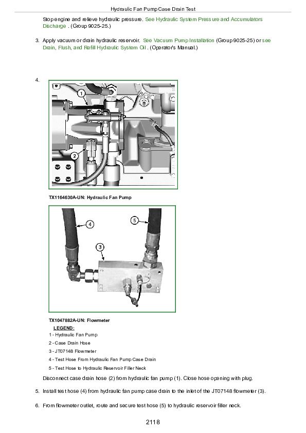
Hydraulic Fan Pump Case Drain Test
Hydraulic Fan Motor Case Drain Test
Hydraulic Reversing Fan Test
Hydraulic Oil Filter Inspection Procedure
Section 9031: Heating and Air Conditioning
Group 05: Theory of Operation
Air Conditioning System Cycle of Operation
Group 10: System Diagrams
Air Conditioner and Heater Component Location
Group 15: Diagnostic Information
Air Conditioning System Does Not Operate
Air Conditioning System Does Not Cool Interior of Cab
Air Conditioning System Runs Constantly, Too Cold
Heating System Does Not Operate
Heating Does Not Warm Interior of Cab
Interior Windows Continue to Fog
Group 25: Tests
R134a Refrigerant Cautions and Proper Handling
R134a Oil Charge Capacity
R134a Refrigerant Charge Capacity
Heater and Air Conditioner Operational Checks
Air Conditioner Compressor Clutch Test
R134a Refrigerant Leak Test
R134a Refrigerant Hoses and Tubing Inspection
Air Conditioner High/Low Pressure Switch Test
Air Conditioner Freeze Control Switch Test
R134a Air Conditioning System Test
Operating Pressure Diagnostic Chart
John Deere 4WD Loaders 744K Series II Operation and Test Service Manual (TM13219X19)


