John Deere 748H Skidder (S.N. 630436- ) Diagnosis and Test Service Technical Manual (TM11797)
Catalog:
Model:
Complete Diagnosis & Tests Technical Manual with electrical wiring diagrams for John Deere 748H Skidders (S.N. 630436- ), with workshop information to maintain, diagnose, and rebuild like professional mechanics.
John Deere 748H Skidder (S.N. 630436- ) workshop Diagnosis & Tests technical manual includes:
* Numbered table of contents easy to use so that you can find the information you need fast.
* Detailed sub-steps expand on repair procedure information
* Numbered instructions guide you through every repair procedure step by step.
* Troubleshooting and electrical service procedures are combined with detailed wiring diagrams for ease of use.
* Notes, cautions and warnings throughout each chapter pinpoint critical information.
* Bold figure number help you quickly match illustrations with instructions.
* Detailed illustrations, drawings and photos guide you through every procedure.
* Enlarged inset helps you identify and examine parts in detail.
TM11797 - John Deere 748H Skidder (S.N. 630436- ) Technical Manual - Diagnosis and Test.pdf
tm11807 - John Deere Remolcador de troncos 748H (630436— ).pdf
tm11802 - John Deere Débusqueurs 748H (630436— ).pdf
tm12068 - John Deere скиддера 748H (630436— ).pdf
PRODUCT DETAILS:
Total Pages: 1,553 pages
File Format: PDF (bookmarked, ToC, Searchable, Printable)
Category: Operation and Test
Language: English Spanish French Russian
Published on 2018/09/13
MAIN SECTIONS
Foreword
Technical Information Feedback Form
General Information
Safety
Diagnostic Trouble Codes (DTC)
Engine Control Unit (ECU) Diagnostic Trouble Codes
Transmission Control Unit (TCU) Diagnostic Trouble Codes
Standard Display Monitor (SDM) Diagnostic Trouble Codes
Flex Load Controller (FLC) Diagnostic Trouble Codes
Sealed Switch Module (SSM) Diagnostic Trouble Codes
Bump Shift Controller (BSC) Diagnostic Trouble Codes
Operational Checkout Procedure
Operational Checkout Procedure
Engine
Theory of Operation
Diagnostic Information
Tests
Electrical System
System Information
System Diagrams
Sub-System Diagnostics
Monitor Operation
References
Power Train
Theory of Operation
Diagnostic Information
Adjustments
Tests
Hydraulic System
Theory of Operation
Diagnostic Information
Adjustments
Tests
Winch
Theory of Operation
Diagnostic Information
Adjustments
Test
Heating and Air Conditoning
Theory Of Operation
Diagnostic Information
Test
TABLE OF CONTENTS
Section 9000: General Information...23
Group 01: Safety...23
Recognize Safety Information...26
Follow Safety Instructions...27
Operate Only If Qualified...28
Wear Protective Equipment...29
Avoid Unauthorized Machine Modifications...30
Inspect Machine...31
Stay Clear of Moving Parts...32
Avoid High-Pressure Fluids...33
Avoid High-Pressure Oils...34
Do Not Use Starting Fluid...35
Work In Ventilated Area...36
Prevent Fires...37
Prevent Battery Explosions...38
Handle Chemical Products Safely...39
Decommissioning — Proper Recycling and Disposal of Fluids and Components...40
Prepare for Emergencies...41
Clean Debris from Machine...42
Use Steps and Handholds Correctly...43
Start Only From Operator's Seat...44
Use and Maintain Seat Belt...45
Prevent Unintended Machine Movement...46
Avoid Work Site Hazards...48
Operate Machine Safely...49
Keep Riders Off Machine...50
Avoid Backover Accidents...51
Avoid Machine Tip Over...52
Operating on Slopes...54
Operating or Traveling On Public Roads...55
Inspect and Maintain ROPS...56
Keep the Operator Protective Structure (OPS) in Place...57
Add and Operate Attachments Safely...58
Park and Prepare for Service Safely...59
Service Tires Safely...61
Service Cooling System Safely...62
Service Accumulator Systems Safely...63
Remove Paint Before Welding or Heating...64
Make Welding Repairs Safely...65
Drive Metal Pins Safely...66
Section 9001: Diagnostic Trouble Codes (DTC)...67
Group 10: Engine Control Unit (ECU) Diagnostic Trouble Codes...76
Engine Control Unit (ECU) Diagnostic Trouble Codes...76
000091.09 - CAN Throttle Message Missing or Late...67
000190.00 - Engine Overspeed Extreme...67
000190.16 - Engine Overspeed Moderate...67
000676.03 - Glow Plug Relay Out of Range High...67
000676.05 - Glow Plug Relay Out of Range Low...67
001075.05 - Low Pressure Fuel Pump Out of Range Low...67
001075.06 - Low Pressure Fuel Pump Out of Range High...67
002003.09 - TCU Communication Data Error...67
002003.13 - TCU Communication Calibrate Error...67
002017.09 - SDM Communication Data Error...67
002017.13 - SDM Communication Calibrate Error...67
Group 20: Transmission Control Unit (TCU) Diagnostic Trouble Codes...103
Transmission Control Unit (TCU) Diagnostic Trouble Codes...103
000158.03 - Switched Power Out of Range High...67
000161.02 - Transmission Input Speed Sensor Erratic or Bad Data...67
000177.00 - Transmission Oil Temperature High...67
000177.03 - Transmission Oil Temperature Sensor Out of Range High...67
000177.04 - Transmission Oil Temperature Sensor Out of Range Low...67
000191.02 - Transmission Output Speed Data Invalid...67
000525.02 - Shift Parameter Erratic or Bad Data...67
000774.04 - Bump Up Shift Switch Short to Ground...67
000775.04 - Bump Down Shift Switch Short to Ground...67
000777.03 - Lockup Clutch Out of Range High...67
000777.05 - Lockup Clutch Out of Range Low...67
003509.04 - Sensor Supply #1 Out of Range Low...67
003510.04 - Sensor Supply #2 Out of Range Low...67
003511.04 - Sensor Supply #3 Out of Range Low...67
003512.04 - Sensor Supply #4 Out of Range Low...67
522002.31 - Upshift and Downshift Inputs Active...67
522003.31 - Neutral, Forward, and Reverse Inputs Passive...67
522004.04 - Park and Not Park Active Out of Range Low...68
522005.03 - Park and Not Park Active Out of Range High...68
522151.31 - Shifter Neutral and Forward Inputs Active...68
522153.31 - Shifter Neutral and Reverse Inputs Active...68
522169.04 - Gear Enable/Differential Lock Switch Out of Range...68
522252.00 - Clutch #1 Hold Value Out of Range High...68
522252.01 - Clutch #1 Hold Value Out of Range Low...68
522253.00 - Clutch #2 Hold Value Out of Range High...68
522253.01 - Clutch #2 Hold Value Out of Range Low...68
522254.00 - Clutch #3 Hold Value Out of Range High...68
522254.01 - Clutch #3 Hold Value Out of Range Low...68
522255.00 - Clutch #4 Hold Value Out of Range High...68
522255.01 - Clutch #4 Hold Value Out of Range Low...68
522256.00 - Clutch A Hold Value Out of Range High...68
522256.01 - Clutch A Hold Value Out of Range Low...68
522257.00 - Clutch B Hold Value Out of Range High...68
522257.01 - Clutch B Hold Value Out of Range Low...68
522258.00 - Clutch C Hold Value Out of Range High...68
522258.01 - Clutch C Hold Value Out of Range Low...68
522259.00 - Clutch D Hold Value Out of Range High...68
522259.01 - Clutch D Hold Value Out of Range Low...68
522284.02 - Transmission Cylinder Speed Data Invalid...68
522398.12 - Not Park and Park Pressure Inputs Active...68
522414.03 - Clutch D Out of Range High...68
522414.05 - Clutch D Out of Range Low...68
522507.14 - Calibrate While Inching...68
523655.03 - Forward and Reverse Inputs Active...68
523689.04 - Differential Lock Short to Ground...68
523697.04 - Inching Pedal Top of Clutch Switch Short to Ground...68
523967.09 - Top of Clutch Input Passive Abnormal Data Rate...68
523699.31 - Speed Clutch Slippage...68
523700.16 - Inching Pedal Limit Exceeded...68
523700.31 - Directional Clutch Slippage...68
523708.02 - Inching Pedal Switch Module Data Invalid...69
523708.04 - Inching Pedal Bottom of Clutch Switch Short to Ground...69
523712.31 - Park Brake Not Set During Calibration...69
523717.31 - Holding Clutch Unexpected Response...69
523718.31 - Cylinder Speed Invalid During Calibration...69
523720.00 - Clutch D Fill Out of Range High...69
523720.01 - Clutch D Fill Out of Range Low...69
523721.00 - Clutch C Fill Out of Range High...69
523721.01 - Clutch C Fill Out of Range Low...69
523722.00 - Clutch B Fill Out of Range High...69
523722.01 - Clutch B Fill Out of Range Low...69
523723.00 - Clutch A Fill Out of Range High...69
523723.00 - Clutch A Fill Out of Range Low...69
523724.00 - Clutch 4 Fill Out of Range High...69
523724.01 - Clutch 4 Fill Out of Range Low...69
523725.00 - Clutch 3 Fill Out of Range High...69
523725.01 - Clutch 3 Fill Out of Range Low...69
523726.00 - Clutch 2 Fill Out of Range High...69
523726.01 - Clutch 2 Fill Out of Range Low...69
523727.00 - Clutch 1 Fill Out of Range High...69
523727.01 - Clutch 1 Fill Out of Range Low...69
523728.31 - Unexpected Cylinder Speed REV Calibration...69
523729.31 - Unexpected Cylinder Speed FWD Calibration...69
523730.31 - No Cylinder Speed Calibration...69
523731.31 - Output Speed During Calibration...69
523732.31 - Engine Speed Too Low During Calibration...69
523733.31 - Engine Speed Too High During Calibration...69
523747.14 - Not Park and Park Pressure Inputs Passive...69
523761.03 - Clutch 4 Out of Range High...69
523761.05 - Clutch 4 Out of Range Low...69
523762.03 - Clutch 3 Out of Range High...69
523762.05 - Clutch 3 Out of Range Low...69
523763.03 - Clutch 2 Out of Range High...69
523763.05 - Clutch 2 Out of Range Low...70
523764.03 - Clutch 1 Out of Range High...70
523764.05 - Clutch 1 Out of Range Low...70
524029.00 - Inching Pedal Sensor Short to Power...70
524029.01 - Inching Pedal Sensor Open or Short to Ground...70
524127.04 - Declutch Pressure Switch Out of Range Low...70
524271.03 - Clutch C Out of Range High...70
524271.05 - Clutch C Out of Range Low...70
524272.03 - Clutch B Out of Range High...70
524272.05 - Clutch B Out of Range Low...70
524273.03 - Clutch A Out of Range High...70
524273.05 - Clutch A Out of Range Low...70
Group 30: Standard Display Monitor (SDM) Diagnostic Trouble Codes...339
000096.03 - Fuel Level Sensor Out of Range High...70
Standard Display Monitor (SDM) Diagnostic Trouble Codes...339
000096.04 - Fuel Level Sensor Out of Range Low...70
000107.00 - Engine Air Filter Restriction Data Above Normal...70
000126.00 - Transmission Oil Filter Restriction Data Above Normal...70
000158.00 - System Voltage Data Above Normal...70
000158.01 - System Voltage Data Below Normal...70
001508.00 - Hydraulic Reservoir Oil Temperature Sensor Data Above Normal...70
001508.03 - Hydraulic Reservoir Oil Temperature Sensor Out of Range High...70
001508.04 - Hydraulic Reservoir Oil Temperature Sensor Out of Range Low...70
001508.16 - Hydraulic Oil Temp Sensor Moderately High Value...70
001713.00 - Hydraulic Oil Filter Restriction Data Above Normal...70
002000.09 - ECU Communication Data Error...70
002000.13 - ECU Communication Calibrate Error...70
002003.09 - TCU Communication Data Error...70
Group 40: Flex Load Controller (FLC) Diagnostic Trouble Codes...70
000111.01 - Engine Coolant Level Low...70
000589.01 - Alternator Speed Slow...70
000746.05 - Differential Lock Open Circuit...70
000746.06 - Differential Lock Short to Ground...70
000977.05 - Reversing Fan Open Circuit...71
000977.06 - Reversing Fan Short to Ground...71
001071.03 - Proportional Fan Solenoid Short to Power...71
001071.05 - Proportional Fan Solenoid Open Circuit or Short to Ground...71
001550.05 - Air Conditioner Clutch Open Circuit...71
001550.06 - Air Conditioner Clutch Short to Ground...71
002000.09 - CAN Communication Lost for ECU...71
002017.09 - CAN Communication Lost for SDM...71
002141.09 - CAN Communication Lost for SSM...71
522170.04 - Tong Squeeze Switch Short to Ground...71
522171.04 - Tong Close Switch Short to Ground...71
522172.04 - Tong Open Switch Short to Ground...71
522174.04 - Grapple Rotate CCW Switch Short to Ground...71
522175.04 - Grapple Rotate CW Switch Short to Ground...71
522176.04 - Secondary Steering Pressure Switch Short to Ground...71
522177.05 - Tong Close Solenoid Open Circuit...71
522177.06 - Tong Close Solenoid Short to Ground...71
522178.05 - Tong Open Solenoid Open Circuit...71
522178.06 - Tong Open Solenoid Short to Ground...71
522179.05 - Grapple Rotate CCW Solenoid Open Circuit...71
522179.06 - Grapple Rotate CCW Solenoid Short to Ground...71
522180.05 - Grapple Rotate CW Solenoid Open Circuit...71
522180.06 - Grapple Rotate CW Solenoid Short to Ground...71
522311.05 - Rear Washer Pump Open Circuit...71
522311.06 - Rear Washer Pump Short to Ground...71
522312.05 - Front Washer Pump Open Circuit...71
522312.06 - Front Washer Pump Short to Ground...71
522426.04 - Rear Wiper Park Short to Ground...71
522427.04 - Front Wiper Park Short to Ground...71
522433.05 - Rear Wiper Open Circuit...71
522433.06 - Rear Wiper Short to Ground...71
522434.05 - Front Wiper Low Speed Open Circuit...71
522434.06 - Front Wiper Low Speed Short to Ground...71
522435.05 - Front Wiper High Speed Open Circuit...72
522435.06 - Front Wiper High Speed Short to Ground...72
523577.05 - Secondary Steering Open Circuit...72
523577.06 - Secondary Steering Short to Ground...72
523795.05 - Dual Mode Steering Open Circuit...72
523795.06 - Dual Mode Steering Short to Ground...72
524097.03 - Accelerator Pedal Short to Power...72
524097.04 - Accelerator Pedal Open or Short to Ground...72
Group 50: Sealed Switch Module (SSM) Diagnostic Trouble Codes...506
Sealed Switch Module (SSM) Diagnostic Trouble Codes...506
002033.09 - SSM Lost Communications...72
520752.04 - SSM Button 17 Stuck...72
520752.09 - SSM Button 17 No CAN Message...72
520753.04 - SSM Button 18 Stuck...72
520753.09 - SSM Button 18 No CAN Message...72
520754.04 - SSM Button 19 Stuck...72
520754.09 - SSM Button 19 No CAN Message...72
520755.04 - SSM Button 20 Stuck...72
520755.09 - SSM Button 20 No CAN Message...72
523335.04 - SSM Button 25 Stuck...72
523335.09 - SSM Button 25 No CAN Message...72
523336.04 - SSM Button 24 Stuck...72
523336.09 - SSM Button 24 No CAN Message...72
523338.04 - SSM Button 23 Stuck...72
523338.09 - SSM Button 23 No CAN Message...72
523339.04 - SSM Button 22 Stuck...72
523339.09 - SSM Button 22 No CAN Message...72
523340.04 - SSM Button 21 Stuck...72
523340.09 - SSM Button 21 No CAN Message...72
523849.04 - SSM Button 16 Stuck...72
523849.09 - SSM Button 16 No CAN Message...72
523850.04 - SSM Button 15 Stuck...72
523850.09 - SSM Button 15 No CAN Message...72
523852.04 - SSM Button 14 Stuck...73
523852.09 - SSM Button 14 No CAN Message...73
523854.04 - SSM Button 13 Stuck...73
523854.09 - SSM Button 13 No CAN Message...73
523855.04 - SSM Button 12 Stuck...73
523855.09 - SSM Button 12 No CAN Message...73
523856.04 - SSM Button 11 Stuck...73
523856.09 - SSM Button 11 No CAN Message...73
523857.04 - SSM Button 10 Stuck...73
523857.09 - SSM Button 10 No CAN Message...73
523858.04 - SSM Button 9 Stuck...73
523858.09 - SSM Button 9 No CAN Message...73
523860.04 - SSM Button 8 Stuck...73
523860.09 - SSM Button 8 No CAN Message...73
523861.04 - SSM Button 7 Stuck...73
523861.09 - SSM Button 7 No CAN Message...73
523862.04 - SSM Button 6 Stuck...73
523862.09 - SSM Button 6 No CAN Message...73
523863.04 - SSM Button 5 Stuck...73
523863.09 - SSM Button 5 No CAN Message...73
523864.04 - SSM Button 4 Stuck...73
523864.09 - SSM Button 4 No CAN Message...73
523865.04 - SSM Button 3 Stuck...73
523865.09 - SSM Button 3 No CAN Message...73
523867.04 - SSM Button 2 Stuck...73
523867.09 - SSM Button 2 No CAN Message...73
523868.04 - SSM Button 1 Stuck...73
523868.09 - SSM Button 1 No CAN Message...73
Group 60: Bump Shift Controller (BSC) Diagnostic Trouble Codes...73
003651.03 - FNR Sensor Circuit Fault...73
003651.04 - FNR Sensor Circuit Fault...73
003651.13 - FNR Sensor Calibration Fault...73
516205.02 - FNR Signal Data Erratic or Intermittent...73
003654.03 - FNR Sensor Circuit Fault...74
003654.04 - FNR Sensor Circuit Fault...74
003654.13 - FNR Sensor Calibration Fault...74
Section 9005: Operational Checkout Procedure...609
Group 10: Operational Checkout Procedure...609
Operational Checkout...680
Section 9010: Engine...750
Group 05: Theory of Operation...750
PowerTech Plus™ 6.8L (6068) John Deere Engine—6.8L Tier 3/Stage IIIA...784
PowerTech Plus™ 6.8L (6068) John Deere Engine—6.8L Stage II...785
Engine Identification...754
Coolant Heater Theory of Operation...760
Engine Fuel System Component Location...762
Engine Cooling System Component Location...763
Engine Intake and Exhaust System Tier 3/Stage IIIA Component Location...764
Engine Intake and Exhaust System Stage II Component Location...765
Coolant Heater Component Location...766
Engine Fluid Sample Port Locations...767
Cold Weather Starting Aid...768
Group 15: Diagnostic Information...750
PowerTech Plus™ 6.8L (6068) John Deere Engine—6.8L Tier 3/Stage IIIA...784
PowerTech Plus™ 6.8L (6068) John Deere Engine—6.8L Stage II...785
Engine Will Not Crank...750
Engine Coolant Temperature Above Normal...750
Engine Coolant Temperature Below Normal...750
Coolant Heater System Check—If Equipped...750
Group 25: Tests...750
PowerTech Plus™ 6.8L (6068) John Deere Engine—6.8L Tier 3/Stage IIIA...784
PowerTech Plus™ 6.8L (6068) John Deere Engine—6.8L Stage II...785
Fuel Line Leakage Test...786
Air Intake System Leakage Test...787
Air Filter Restriction Switch Test...790
Intake Manifold Pressure Test—Turbocharger Boost—6.8L Stage II...793
Engine Slow and Fast Idle Speed Check...795
Section 9015: Electrical System...796
Group 05: System Information...796
Electrical Diagram Information...806
Group 10: System Diagrams...796
Fuse Specifications...817
System Functional Schematic, Wiring Diagrams, and Component Locations Legend...822
System Functional Schematic and Section Legend...830
Power and Ground Cables Component Location...840
Load Center Harness (W10) Component Location...841
Load Center Harness (W10) Wiring Diagram...843
Engine Interface Harness (W11) Component Location...848
Engine Interface Harness (W11) Wiring Diagram...849
Engine Harness (W12) Component Location...850
Engine Harness (W12) Wiring Diagram...853
Transmission Harness (W13) Component Location...856
Transmission Harness (W13) Wiring Diagram...857
Hydraulic Reservoir Harness (W14) Component Location...858
Hydraulic Reservoir Harness (W14) Wiring Diagram...860
Fuel Sensor and Backup Alarm Harness (W15) Component Location...862
Fuel Sensor and Backup Alarm Harness (W15) Wiring Diagram...863
Cab Roof Harness (W16) Component Location...864
Cab Roof Harness (W16) Wiring Diagram...866
Radio Harness (W17) Component Location—If Equipped...869
Radio Harness (W17) Wiring Diagram—If Equipped...870
Secondary Steering Harness (W19) Component Location—If Equipped...871
Secondary Steering Harness (W19) Wiring Diagram—If Equipped...873
JDLink™ System Harnesses Component Location—MIG/GTT...874
JDLink™ System Harnesses Component Location—MTG/SAT...876
JDLink™ System Wiring Diagrams—MIG/GTT...878
JDLink™ System Wiring Diagrams—MTG/SAT...879
Pilot Control Harness (W24) Component Location...881
Pilot Control Harness (W24) Wiring Diagram...882
Diesel Fired Coolant Heater (DFCH) Harnesses (W25 and W26) Component Location—If Equipped...883
Diesel Fired Coolant Heater (DFCH) Harnesses (W25 and W26) Wiring Diagram—If Equipped...885
Forward, Neutral, and Reverse (FNR) Shift Lever Harness (W28) Component Location (S.N. 661906— )...887
Forward, Neutral, and Reverse (FNR) Shift Lever Harness (W28) Wiring Diagram (S.N. 661906— )...888
Group 15: Sub-System Diagnostics...797
Power and Charge Circuits Theory of Operation...894
Start Circuit Theory of Operation...899
Park Brake Circuit Theory of Operation...903
Controller Area Network (CAN) Circuit Theory of Operation...907
Engine Control Unit (ECU) Circuit Theory of Operation...909
Standard Display Monitor (SDM) Circuit Theory of Operation...921
Transmission Control Unit (TCU) Circuit Theory of Operation...925
JDLink™ Circuit Theory of Operation—If Equipped...936
Declutch Circuit Theory of Operation...938
Differential Lock Circuit Theory of Operation...940
Proportional Fan Speed and Reversing Fan Circuits Theory of Operation...943
Grapple Control Circuit Theory of Operation...947
Secondary Steering Circuit Theory of Operation...950
Dual Mode Steer Circuit Theory of Operation...954
Windshield Washer and Wiper Circuits Theory of Operation...956
Heater, Air Conditioner, and Precleaner Circuits Theory of Operation...960
Work Lights Circuits Theory of Operation...965
Group 16: Monitor Operation...797
Standard Display Monitor (SDM)—Service Mode...970
Standard Display Monitor (SDM)—Clear Codes...972
Standard Display Monitor (SDM)—Transmission Temperature...973
Standard Display Monitor (SDM)—Transmission Calibration...974
Standard Display Monitor (SDM)—Engine Temperatures...975
Standard Display Monitor (SDM)—Engine Pressures...976
Standard Display Monitor (SDM)—Engine Speeds...977
Standard Display Monitor (SDM)—Engine Performance...978
Standard Display Monitor (SDM)—Engine Live Values...979
Standard Display Monitor (SDM)—Fan Diagnostics...980
Standard Display Monitor (SDM)—Monitor Diagnostics...981
Standard Display Monitor (SDM)—Software...982
Standard Display Monitor (SDM)—Hide Menu...983
Standard Display Monitor (SDM)—Restore Defaults...984
Standard Display Monitor (SDM)—Reverse Fan Cycle...985
Standard Display Monitor (SDM)—Machine Option...986
Group 20: References...798
Electrical Component Specifications...992
JDLink™ System Identification...997
JDLink™ Connection Procedure—If Equipped...1000
Service ADVISOR™ Connection Procedure...1001
Service ADVISOR™ Diagnostic Application...1004
Reading Diagnostic Trouble Codes (DTCs) With Service ADVISOR™ Diagnostic Application...1005
Intermittent Diagnostic Trouble Code (DTC) Diagnostics...1008
Transmission Diagnostic Trouble Codes—Limp Home Mode and Inchless Power Shift...1009
Controller Area Network (CAN) Circuit Test...1010
Bump Shifter Test...1014
Accelerator Pedal Sensor Test...1016
Alternator Test...1018
Relay Test...1020
Diode Test...1023
Battery Test Procedure...1024
Transmission Control Unit (TCU) Calibration...1025
Troubleshooting Transmission Gear Solenoid...1027
Electronic Controllers Remove and Install...1028
Connector Terminal Test...1030
Disconnect Tab Retainer Connectors...1033
Disconnecting Spring Wire Clip Connectors...1034
Remove Connector Body from Blade Terminals...1035
Replace Metri-Pack® (Pull Type) Connectors...1036
Replace Metri-Pack® (Push Type) Connectors...1038
Replace Metri-Pack® Connectors...1039
Replace DEUTSCH® Circular Connectors...1041
Replace DEUTSCH® Rectangular or Triangular Connectors...1043
Install DEUTSCH® Contact...1045
Replace WEATHER PACK® Connector...1047
Install WEATHER PACK® Contact...1049
Replace CINCH™ Connectors...1051
Install CINCH™ Contact...1053
Repair 32 and 48 Way CINCH™ Connectors...1055
Section 9020: Power Train...1059
Group 05: Theory of Operation...1059
Power Train Component Overview...1063
DF180 Series Powershift Transmission...1064
TeamMate Axles...1065
Transmission Operation...1066
Transmission Component Identification...1067
Transmission Hydraulic System Operation...1224
Transmission Charge Pump Operation...1072
Transmission Filter Bypass Valve Operation...1074
Transmission Control Valve Port Identification...1076
Transmission Proportional Solenoid Valves Identification...1078
Transmission Control Valve Operation...1079
Transmission Pressure Regulator Valve Operation...1081
Park Brake and Differential Lock Control Valve...1083
Park Brake Control Circuit...1085
Park Brake Manual Release Operation...1090
Differential Lock Control Circuit...1091
Group 15: Diagnostic Information...1059
Transmission Overfills With Oil...1059
Transmission Clutch Slippage...1059
Transmission Shifts Too Slow...1059
Transmission Shifts Too Fast...1059
Park Brake Activates When Service Brakes Are Applied (No Load on Engine While in Gear)...1059
Machine Will Not Move (Load on Engine or Engine Stalls When Shifted Into Gear)...1059
Machine Creeps in Neutral (Load Put on Engine When Service Brakes Are Applied)...1059
Transmission System Overheats...1059
Lube Pressure Low, Transmission Charge Pressure Normal...1059
Excessive Transmission Noise Under Load or No Load...1059
Machine Makes Excessive Transmission Noise When Moving...1059
Erratic Transmission Oil Pressure...1059
Excessive Transmission Oil Pressure...1059
Low Transmission Oil Pressure in All Gears...1059
Low Transmission Oil Pressure in One Gear but Correct in Other Gears...1060
Transmission Breather Oil Leakage...1060
Filter or Filter Oil Lines Blow Out...1060
Low Lube Pressure (Not All Gears)...1060
Excessive Lube Pressure (Not All Gears)...1060
Low Transmission Oil Cooler Inlet Pressure, Correct Lube Pressure...1060
Low Transmission Oil Cooler Inlet Pressure and Lube Pressure...1060
Transmission Oil Cooler Externally Leaking...1060
Machine “Jumps” When Inching Pedal Engaged...1060
Machine Lacks Power...1060
Excessive Machine Vibration...1060
Cold Weather Disconnect Slips...1060
Disconnect Clutch Noisy or Chatters...1060
Excessive Drive Line Vibration...1060
Park Brake Comes On While Using a Hydraulic Function...1060
Park Brake Engages While Machine Is Moving...1060
Park Brake Will Not Release...1060
No Differential Lock Operation...1060
Differential Lock Slippage...1060
Excessive Differential and/or Axle Noise...1060
Oil Seepage From Outer Axle Seal...1060
Power Train Component Location...1179
Group 20: Adjustments...1060
Inching Pedal Adjustment...1184
Park Brake Manual Release Procedure...1187
Cold Weather Disconnect Linkage Adjustment—If Equipped...1190
Group 25: Tests...1060
JT02156A Digital Pressure/Temperature Analyzer Installation...1194
Transmission Oil Warmup Procedure...1195
Transmission Pump Flow Test...1196
Transmission System Pressure Test...1199
Transmission Lube Circuit Pressure Test...1201
Transmission Control Circuit Pressure Test...1204
Transmission Cooler Relief Valve Pressure Test...1207
Park Brake Pressure Test...1209
Differential Lock Pressure Test...1213
Section 9025: Hydraulic System...1218
Group 05: Theory of Operation...1218
Hydraulic System Operation...1224
Cooling Loop and Reversing Fan Circuit Operation...1226
Service Brake Hydraulic Circuit Operation...1228
Steering and Secondary Steering Hydraulic Circuit Operation...1230
Dual Mode Steering Hydraulic Circuit Operation...1232
Pilot Control Hydraulic Circuit Operation...1235
Grapple Rotate Hydraulic Circuit Operation...1237
Main Hydraulic Pump and Pressure Compensator Operation...1239
Brake Accumulator Operation...1242
Hydraulic Reservoir Operation...1243
Hydraulic Oil Return Filter Operation...1245
Hydraulic Fan Filter Operation...1247
Brake Valve Operation...1248
Priority Valve Operation...1250
Steering Valve and System Operation...1254
Secondary Steering Valve Operation...1256
120 Series Cylinder Operation...1258
Blade Valve Section Operation...1260
Arch and Boom Valve Section Operation...1262
System Relief Valve Operation...1263
Circuit Relief Valve—Adjustable Operation...1265
Circuit Relief Valve—Non-Adjustable Operation...1267
Grapple Tong Valve Section Operation...1268
Grapple Tong Flow Divider Operation...1270
Pilot Controller Operation...1272
Grapple Rotate Solenoid Valve Operation...1273
Dual Mode Steering Solenoid Valve Operation...1275
Rotary Manifold Operation...1277
Fan Pump Operation...1278
Fan Variable Speed and Reversing Control Valve Operation...1281
Fan Motor Operation...1283
Hydraulic Oil Cooler Operation...1284
Cab Tilt Circuit Operation...1285
Group 15: Diagnostic Information...1219
Hydraulic System Overheating...1219
Hydraulic Function Drifts Down...1219
No Steering or Hydraulic Functions...1219
Hydraulic Functions Slow...1219
Individual Functions Slow (Cycle Time Slow)...1219
No Hydraulic Functions (Steering Normal)...1219
Low Hydraulic Power (Pressure)...1219
Excessive Hydraulic Pump Noise...1219
Function Powers Up or Down Without Moving Lever...1219
Grapple Rotate Stalls...1219
Grapple Rotates Too Fast...1219
Grapple Rotates Slow...1219
Tongs Do Not Close Evenly...1219
Tongs Open or Close Slowly...1219
Grapple Loses Logs During Skidding...1219
Transmission Overfills With Oil...1219
No Steering (Hydraulic Functions Normal)...1219
Steering Valve Does Not Center...1219
Steering Valve Locks Up...1219
Frames Turn Wrong Direction...1219
Steering Slow or Hard...1219
Steering Erratic or Spongy...1219
Machine Wanders...1219
Quick Steer Mode Not Engaging...1219
Quick Steer Mode Not Disengaging...1219
Quick Steer Mode Engaging When Disengaged...1219
Poor or No Brakes (Other Hydraulic Systems Normal)...1219
Brakes Overly Aggressive...1219
Brakes Drag...1219
Brakes Chatter or Noisy...1219
Delay in Braking...1220
Fan Does Not Reach Full Speed (Both Directions)...1220
Fan Does Not Reach Full Speed (Forward Direction Only)...1220
Fan Does Not Reach Full Speed (Reverse Direction Only)...1220
Fan Does Not Spin (Both Directions)...1220
Fan Does Not Slow Down Before Reversing...1220
High Fan Cooler Pressure or Pressure Spikes...1220
High Return Pressure at Fan Reversing Control Valve Port T...1220
High Flow From Fan Motor Case Drain...1220
Fan Pump Is Cavitating...1220
Hydraulic System Component Location...1363
Hydraulic System Schematic...1367
Group 20: Adjustments...1220
Service Brake Pedal Adjustment...1371
Service Brake Inspection and Adjustment...1372
Service Brake Bleeding Procedure...1373
Grapple Dampener Adjustment...1377
Group 25: Tests...1220
D15032NU Vacuum Pump Installation...1382
JT02156A Digital Pressure and Temperature Analyzer Kit Installation...1384
JT07148 Digital Hydraulic Tester...1385
Hydraulic Oil Warmup Procedure...1386
Main Hydraulic Pump Standby Pressure Test...1387
Main Hydraulic Pump Flow Test...1391
Main Hydraulic Pump Leakage Test...1394
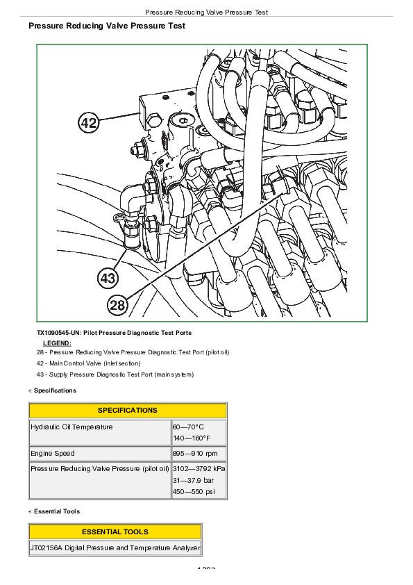
Pressure Reducing Valve Pressure Test...1397
Pilot Controller Pressure Test...1399
Priority Valve and Relief Valve Pressure Test...1402
Priority Valve Port LS Flow Test...1405
Priority Valve and Relief Valve Leakage Test...1407
System and Circuit Relief Valve Pressure Test...1409
Hydraulic Component Leakage Test...1414
Cylinder Leakage Test...1418
Cylinder Drift Test...1420
Dual Mode Steering Engagement Pressure Test...1422
Grapple Rotate Motor Crossover Relief Valve Pressure Test...1425
Grapple Rotate Solenoid Valve Neutral Leakage Test...1427
Grapple Tong Flow Divider Relief Valve Test...1429
Rotary Manifold Center Seal Leakage Test...1431
Rotary Manifold Drain and Lower Seal Leakage Test...1433
Service Brake Valve and Accumulator Pressure Test...1435
Service Brake Valve Leakage Test...1438
Steering Valve Neutral Leakage Test...1440
Hydraulic Oil Filter Inspection Procedure...1442
Cooling Fan Circuit Test...1443
Fan Motor Case Drain Test...1448
Secondary Steering Operation Test...1450
Section 9030: Winch...1451
Group 05: Theory of Operation...1451
John Deere 4000 and 6000 Winches...1453
Group 15: Diagnostic Information...1451
Winch Control Lever Effort Excessive...1451
Winch Clutch Slips...1451
Winch Free Spool Effort Excessive...1451
Winch Brake Will Not Hold...1451
Winch Will Not Free Spool...1451
Transmission Oil Level Varies Excessively...1451
Winch Makes Grinding Noise When Going from FREE SPOOL to BRAKE OFF...1451
Winch Component Location...1469
Winch Hydraulic Schematic...1470
Group 20: Adjustments...1451
Winch Control Cable Adjustment Check...1472
Brake Off Adjustment—4000 Series Winch...1473
Brake Off Adjustment—6000 Series Winch...1478
Group 25: Test...1451
Winch System Pressure Test...1487
Winch Leakage Test...1492
Winch Drum Rolling Drag Test...1496
Section 9031: Heating and Air Conditoning...1498
Group 05: Theory Of Operation...1498
Air Conditioning System Cycle of Operation...1501
Group 15: Diagnostic Information...1498
Air Conditioning System Visual Checks...1507
Blower Does Not Operate in Any Speed...1498
Blower Does Not Operate in Low Speed...1498
Blower Does Not Operate in Medium Speed...1498
Blower Does Not Operate in High Speed...1498
Blower Does Not Operate in Purge Speed...1498
Air Conditioner Does Not Operate...1498
Air Conditioner Does Not Cool Cab Interior...1498
Air Conditioner Runs Constantly...1498
Interior Windows Continuously Foggy...1498
Heater Does Not Operate...1498
Heater Does Not Warm Cab Interior...1498
Heating and Air Conditioning System Component Location...1540
Group 25: Tests...1498
R134a Air Conditioning System Test...1545
Air Conditioner Freeze Control Switch Test...1549
Air Conditioning Compressor Clutch Test...1551
Air Conditioning High/Low Pressure Switch Test...1552
Air Conditioning Expansion Valve Test...1554
Refrigerant Leak Test...1557
John Deere 748H Skidder (S.N. 630436- ) Diagnosis and Test Service Technical Manual (TM11797)


