John Deere Compact Loaders 244J Operation and Test Service Manual (TM11214)
Catalog:
Model:
Complete Diagnosis and Test manual with Electrical Wiring Diagrams for John Deere Compact Loaders 244J (SN.23290-), with all the workshop information to maintain, diagnose, andrebuild like professional mechanics.
John Deere Compact Loaders 244J workshop service & Operation and Test manual includes:
* Numbered table of contents easy to use so that you can find the information you need fast.
* Detailed sub-steps expand on Operation and Test procedure information
* Numbered instructions guide you through every Operation and Test procedure step by step.
* Troubleshooting and electrical service procedures are combined with detailed wiring diagrams for ease of use.
* Notes, cautions and warnings throughout each chapter pinpoint critical information.
* Bold figure number help you quickly match illustrations with instructions.
* Detailed illustrations, drawings and photos guide you through every procedure.
* Enlarged inset helps you identify and examine parts in detail.
TM11214 - John Deere 244J (23290— ) Compact Loaders Technical Manual - Operation and Test.pdf
tm11302 - John Deere Chargeur 244J (23290— ).pdf
Total Pages: 813 pages
File Format: PDF (bookmarked, ToC, Searchable, Printable)
Category: Operation and Test
Language: English French
Published on 2020/01/258
MAIN SECTIONS
Foreword
General Information
Safety
Specifications
Torque Values
Fuels And Lubricants
Operational Checkout Procedure
Operational Checkout Procedure
Engine
Theory Of Operation
System Operational Checks
Diagnostic Information
Adjustments
Tests
Electrical System
System Information
System Diagrams
Sub-System Diagnostics
References
Power Train
Theory Of Operation
System Operational Checks
Diagnostic Information
Adjustments
Tests
Hydraulic System
Theory Of Operation
Operational Checkout
Diagnostic Information
Adjustments
Tests
Table of Contents
Foreword
Technical Information Feedback Form
Section 9000: General Information
Group 01: Safety Information
Recognize Safety Information
Follow Safety Instructions
Operate Only If Qualified
Wear Protective Equipment
Avoid Unauthorized Machine Modifications
Add Cab Guarding For Special Uses
Inspect Machine
Stay Clear of Moving Parts
Avoid High-Pressure Oils
Beware of Exhaust Fumes
Prevent Fires
Prevent Battery Explosions
Handle Chemical Products Safely
Dispose of Waste Properly
Prepare for Emergencies
Use Steps and Handholds Correctly
Start Only From Operator's Seat
Use and Maintain Seat Belt
Prevent Unintended Machine Movement
Avoid Work Site Hazards
Use Special Care When Operating Loader
Keep Riders Off Machine
Avoid Backover Accidents
Avoid Machine Tip Over
Operating on Slopes
Operating or Traveling On Public Roads
Inspect and Maintain ROPS
Add and Operate Attachments Safely
Park And Prepare For Service Safely
Service Cooling System Safely
Remove Paint Before Welding or Heating
Make Welding Repairs Safely
Drive Metal Pins Safely
Section 9001: Diagnostic Trouble Codes (DTC)
Group 10: Engine Control Unit (ECU) Diagnostic Trouble Codes
Engine Control Unit (ECU) Diagnostic Trouble Codes
000029.03 - Throttle #2 Voltage Out of Range High
000029.04 - Throttle #2 Voltage Out of Range Low
000029.13 - Throttle #2 Voltage Out of Range Low or High
000091.03 - Throttle #1 Voltage Out of Range High
000091.04 - Throttle #1 Voltage Out of Range Low
000091.13 - Throttle #1 Voltage Out of Range Low or High
000091.14 - Throttle Voltage Mismatch
000190.00 - Engine Speed High—Most Severe Level
000627.18 - Battery Voltage Low—Moderately Severe Level
000970.31 - CAN Message Requesting Engine Shutdown
Group 20: Chassis Control Unit (CCU) Diagnostic Trouble Codes
Chassis Control Unit (CCU) Diagnostic Trouble Codes
000100.01 (E6004) - Engine Oil Pressure Low
000100.01 (E6025) - Engine Oil Pressure Extremely Low
000111.01 (E6008) - Engine Coolant Level Low
000167.02 (E6016) - Alternator Not Supplying Power
000168.16 (E6009) - Battery Voltage High
000168.18 (E600A) - Battery Voltage Low
000174.00 (E6022) - Fuel Temperature Exceeds Safety Threshold
000190.02 (E601E) - Alternator Signal Mismatch
000246.12 (EB01D) - CCU Memory Error
000246.31 - CCU Memory Error
000251.14 - Time Was Changed in CCU
000444.01 (E6026) - Battery Voltage Low With Engine Running
000629.12 - CCU Hardware or Software Malfunction
000629.14 (EB017) - CCU Proper Shutdown
000702.04 (E406C) - Fourth Function Hydraulics Solenoid #1 Open Circuit
000702.06 (E406B) - Fourth Function Hydraulics Solenoid #1 Short to Ground
000703.05 (E406E) - Fourth Function Hydraulics Solenoid #2 Open Circuit
000703.06 (E406D) - Fourth Function Hydraulics Solenoid #2 Short to Ground
000705.12 (EB011) - CCU Internal Malfunction
000706.14 (EB02E) - CAN Error
000706.31 (EB030) - CAN Error
000707.14 (EB02F) - CAN Error
000707.31 (EB031) - CAN Error
000708.12 (EB034) - CAN Error
000746.05 (E406A) - Differential Lock Solenoid Open Circuit
000746.06 (E4069) - Differential Lock Solenoid Short to Ground
000785.05 (E4003) - Pilot Enable Solenoid Open Circuit
000785.06 (E4002) - Pilot Enable Solenoid Short to Ground
000829.03 (E300C) - Fuel Level Sensor Short to Power
000829.04 (E300B) - Fuel Level Sensor Open or Short to Ground
001071.05 (E400B) - Fan Motor Solenoid Open Circuit
001071.06 (E400A) - Fan Motor Solenoid Short to Ground
001638.00 (E2013) - Hydraulic Oil Temperature High
001638.04 (E3010) - Hydraulic Oil Temperature Sensor Short to Ground
001638.05 (E3011) - Hydraulic Oil Temperature Sensor Open Circuit
002000.12 (EA02F) - CAN Communication Lost for ECU
002023.09 (A005) - CAN Communication Lost for Monitor
002630.00 (E6001) - Manifold Air Temperature High
002630.00 (E6020) - Manifold Air Temperature Exceeds Safety Threshold
002858.02 (EB01B) - CCU Memory Error
004076.00 (E601F) - Coolant Temperature Exceeds Safety Threshold
298935.03 (EB010) - CCU Internal Malfunction
298936.03 (E5050) - Forward and Reverse Solenoid Circuits Mismatch
299621.02 - CCU Memory Error
299621.12 (EB01F) - CCU Memory Error
522373.14 (EB012) - CCU Internal Malfunction
522379.05 (E4001) - Park Brake Release Solenoid Open Circuit
522379.06 (E4000) - Park Brake Release Solenoid Short to Ground
522383.05 (E4025) - Reverse Travel Solenoid Open Circuit
522383.06 (E4024) - Reverse Travel Solenoid Short to Ground
522386.05 (E4023) - Forward Travel Solenoid Open Circuit
522386.06 (E4022) - Forward Travel Solenoid Short to Ground
522399.05 (E4066) - LO/HI Speed Solenoid Open Circuit
522399.06 (E4065) - LO/HI Speed Solenoid Short to Ground
522401.03 (E303B) - Ground Speed Sensor Short to Power
522401.04 (E3014) - Ground Speed Sensor Short to Ground
522401.05 (E3015) - Ground Speed Sensor Open Circuit
522411.12 (E5035) - Forward, Neutral, Reverse Switch Signal Mismatch
522429.01 (E2001) - Engine ON, Steering System Pressure Switch Open
522429.03 (E2003) - Secondary Steering System Pressure Switch Closed With No Check
522429.04 (E3001) - Steering System Pressure Switch Short to Ground
522475.14 (EB036) - Valid Access Code Entered
522477.01 (E6006) - Engine Air Filter Restricted
522478.14 (E204C) - Service Hours Changed
522976.14 (EB037) - CCU Software Updated
523137.01 (E2002) - Secondary Steering Pump Check Failed
523137.03 (E2000) - Engine OFF, Steering System Pressure Switch Closed
523137.04 (E3000) - Secondary Steering System Pressure Switch Short to Ground
523216.05 (EB00C) - CCU Sensor 4 Voltage Low
523217.05 (EB00B) - CCU Sensor 3 Voltage Low
523218.05 (EB00A) - CCU Sensor 2 Voltage Low
523310.02 (EB01C) - CCU Memory Error
523310.13 (EB018) - CCU Memory Error
523572.31 (EB016) - CCU Improper Shutdown
523577.05 (E4067) - Secondary Steering Relay Open or Short to Ground
523706.12 (EB000) - CCU Internal Malfunction
523773.02 (EB013) - CAN1 Abnormal Error Rate
523777.14 (E204D) - Secondary Steering Was Activated
524055.02 (EB00D) - CCU Internal Malfunction
524189.19 (EB015) - CCU Memory Error
524201.12 (A025) - Monitor Display Internal Error
524215.02 (EB014) - CAN2 Abnormal Error Rate
524232.01 (E2016) - Brake Accumulator Pressure Low
524232.31 (E204F) - Park Brake Pressure Switch Signal Mismatch
524323.04 (E3002) - Brake Accumulator Pressure Switch Short to Ground
524277.14 (E5066) - Drive Shaft Overspeed
(E601C) - Calculation Error, Engine
(E601D) - Calculation Error, Engine
Section 9005: Operational Checkout Procedure
Group 10: Operational Checkout Procedure
Operational Checkout
Section 9010: Engine
Group 05: Theory of Operation
PowerTech E™ 2.4 L John Deere Engine
Group 15: Diagnostic Information
PowerTech E™ 2.4 L John Deere Engine
Engine Cooling System Component Location
Engine Fuel System Component Location
Engine Intake and Exhaust Component Location
Group 25: Tests
PowerTech E™ 2.4 L John Deere Engine
Engine Idle Speeds Check
Intake Manifold Pressure Test—Turbocharger Boost
Section 9015: Electrical System
Group 05: System Information
Electrical Diagram Information
Electrical Schematic Symbols
Group 10: System Diagrams
Fuse and Relay Specifications
System Functional Schematic, Wiring Diagrams, and Component Locations Master Legend
System Functional Schematic and Section Legend
Batteries and Power Cables (W5) Component Location
Engine Harness (W6) Component Location
Engine Harness (W6) Wiring Diagram
Loader/Rear Frame Harness (W7) Component Location
Loader/Rear Frame Harness (W7) Wiring Diagram
Cab Main Harness (W8) Component Location
Cab Main Harness (W8) Wiring Diagram
Cab Roof Harness (W9) Component Location
Cab Roof Harness (W9) Wiring Diagram
Rear Lights Harness (W10) Component Location
Rear Lights Harness (W10) Wiring Diagram
Air Conditioning Thermostat and Blower Harness (W11) Component Location
Air Conditioning Thermostat and Blower Harness (W11) Wiring Diagram
Air Conditioning Harness (W12) Component Location—If Equipped
Air Conditioning Harness (W12) Wiring Diagram—If Equipped
Fourth Function Harness (W13) Component Location—If Equipped
Fourth Function Harness (W13) Wiring Diagram—If Equipped
Ride Control Harness (W14) Component Location—If Equipped
Ride Control Harness (W14) Wiring Diagram—If Equipped
Group 15: Sub-System Diagnostics
Power Circuit Theory of Operation
Start and Charge Circuits Theory of Operation
Preheat Circuit Theory of Operation
Controller Area Network (CAN) Theory of Operation
Engine Control Unit (ECU) Circuits Theory of Operation
Chassis Control Unit (CCU) Circuits Theory of Operation
Monitor Display Circuit Theory of Operation
Park Brake Release Circuit Theory of Operation
Forward, Reverse, LO/HI Speed, and Backup Alarm Circuits Theory of Operation
Pilot Enable, Return-to-Dig, and Boom Float Circuits Theory of Operation
Ride Control Circuit Theory of Operation
Differential Lock Circuit Theory of Operation
Hydraulic Fan Circuit Theory of Operation
Fourth Function Circuit Theory of Operation
Hazard and Turn Lights Circuits Theory of Operation
Quick Disconnect Circuit Theory of Operation
Group 20: References
Electrical Component Specifications
Service ADVISOR™ Diagnostic Application
Service ADVISOR™ Connection Procedure
Tuple Error Correction—Service ADVISOR™ Connection
Reading Diagnostic Trouble Codes with Service ADVISOR™ Diagnostic Application
Controller Payload Download
Controller Payload Update
Alternator Test
CAN Circuit Test
Wire Harness Test
Engine Speed Control Pedal Sensor Test
Sensor Circuit Check
Monitor Display Remove and Install
Chassis Control Unit (CCU) Remove and Install
Engine Control Unit (ECU) Remove and Install
Ground Speed Sensor Install
Return-to-Dig (RTD) Adjustment
Intermittent Diagnostic Trouble Code (DTC) Diagnostics
Connector Terminal Test
Replace Metri-Pack® (Push Type) Connectors
Replace Metri-Pack® Connectors
Replace DEUTSCH® Circular Connectors
Replace DEUTSCH® Rectangular or Triangular Connectors
Install DEUTSCH® Contact
Replace WEATHER PACK® Connector
Install WEATHER PACK® Contact
Replace CINCH™ Connectors
Install CINCH™ Contact
Repair 32 and 48 Way CINCH™ Connectors
Remove Connector Body from Blade Terminals
Section 9020: Power Train
Group 05: Theory Of Operation
Power Train Description
Hydrostatic Transmission Operation—Neutral
Hydrostatic Transmission Operation—Forward (Low Speed)
Hydrostatic Transmission Operation—Forward (High Speed)
Hydrostatic Transmission Operation—Reverse (Low Speed)
Hydrostatic Pump Operation
Hydrostatic Pump Swash Plate Operation
Hydrostatic Pump Control Operation—Reverse (Engine Speed at Less than Fast Idle)
Hydrostatic Pump Control Operation—Forward (Engine Speed at Fast Idle)
High Pressure Relief Valve Operation
Hydrostatic Motor Operation—Neutral
Hydrostatic Motor Operation—Reverse (Low Speed)
Hydrostatic Motor Operation—Forward (High Speed)
Inching Valve Operation
Brake Valve Operation
Service and Park Brake Operation
Park Brake Release Solenoid Valve Operation
Park Brake Operation
Service Brakes Operation
Differential Lock Operation
Group 15: Diagnostic Information
Machine Does Not Move
Machine Does Not Move at 1050—1150 RPM
Machine Moves in One Direction Only
Machine Drives Erratically
Machine Moves in Wrong Direction
Cannot Find or Hold Neutral
Hydraulic Oil Overheats (Machine Shifts to Low Speed Automatically)
Slow Acceleration—Fast Deceleration
Lack of Power or Sluggish
Foaming Oil
Machine Vibrates
Differential Low on Oil
Excessive Differential and/or Axle Noise
Oil Seeping From Outer Axle Seal
Axle Overheats
Excessive Driveline Vibration or Noise
Park Brake Will Not Hold
Park Brake Overheats
Park Brake Indicator in Monitor Does Not Come ON When Park Brake Applied
Park Brake Will Not Apply
Park Brake Will Not Release
Poor or No Service Brakes
Service Brakes Aggressive
Service Brakes Dragging
Service Brakes Chatter
Power Train Component Location
Service and Park Brake System Component Location
Hydrostatic Transmission Schematic
Service Brake, Park Brake, and Differential Lock System Schematic
Group 20: Adjustments
Hydrostatic Pump Servo Piston Neutral Adjustment
Hydrostatic Motor Minimum Displacement Adjustment
Brake/Inching Pedal Linkage Adjustment
Group 25: Tests
Before Performing Hydrostatic Transmission Tests
Neutral Charge Relief Valve Pressure Test and Adjustment
Hydrostatic Pump Begin Regulation Test and Adjustment
Hydrostatic Pump Performance (Timing) Test and Adjustment
High Pressure Relief Valve Test and Adjustment
Hydrostatic Pump Pressure Override (POR) Valve Pressure Test and Adjustment
Hydrostatic Motor Begin Regulation of Displacement Control Valve Test and Adjustment
Hydrostatic Pump Isolation Procedure
Directional Control Valve Spool Leakage Test
Hydrostatic Adjusting Screws (With Tamper-Proof Caps)
Park Brake Release Pressure Test
Section 9025: Hydraulic System
Group 05: Theory of Operation
Hydraulic System Operation
Hydraulic Pump Operation
Hydraulic Fan Operation
Priority Valve Operation
Orbital Steering Circuit Operation
Orbital Steering Valve Operation
Steering Cylinder Relief Valve Operation
Loader Control Valve Operation
Loader Relief and Anticavitation Valves Operation
Ride Control Valve Operation—If Equipped
Pilot Control Valve Operation
Pilot Enable Solenoid Valve Operation
Group 15: Diagnostic Information
Hydraulic System Schematic
Orbital Steering System Schematic
No Hydraulic Functions
Slow Hydraulic Functions
Noisy Hydraulic Pumps
Boom Float Function Does Not Work
One Hydraulic Function Does Not Work
Low Hydraulic Power
Function Drifts Down
Boom Down Does Not Work (Engine Off)
Oil Overheats
Function Drops Before Rising When Valve Is Activated
Hydraulic Oil Foams
No Steering Functions
Constant Steering to Maintain Straight Travel
No Steering Function During Slow Steering Wheel Movement
Steering Wheel Turns With No Resistance and Causes No Frame Movement
Erratic Steering
Spongy or Soft Steering
Free Play at Steering Wheel
Steering Wheel Does Not Immediately Return to Neutral When Released
Orbital Steering Valve Locks Up
Abrupt Steering Wheel Oscillation
Steering Wheel Turns by Itself
Machine Turns in Opposite Direction
Machine Turns When Orbital Steering Valve Is in Neutral
Hydraulic Fan Does Not Reach Full Speed
Hydraulic Fan Runs at Full Speed Only
Hydraulic Fan Does Not Spin
Loader System Component Location
Loader Auxiliary Systems Component Location
Orbital Steering System Component Location
Group 20: Adjustments
Steering Alignment Adjustment
Group 25: Test
Hydraulic Oil Warm-Up Procedure
Hydraulic System Pressure and Accumulators Discharge Procedure
Digital Pressure and Temperature Analyzer Installation
Hydraulic Pump Flow Test
Orbital Steering System Relief Pressure Test
Steering Cylinder Leakage Test
Loader System Relief Valve Pressure Test
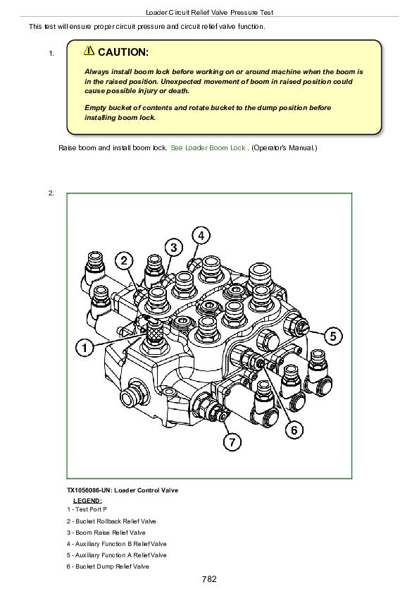
Loader Circuit Relief Valve Pressure Test
Ride Control System Relief Valve Pressure Test
Loader Cylinder Drift Test
Boom and Bucket Cylinder Leakage Test
Pilot Control Valve Pressure Test
Hydraulic Fan Motor Speed Test
Hydraulic Fan Pump Pressure and Flow Test
Section 9031: Heating and Air Conditioning
Group 05: Theory of Operation
Air Conditioning System Cycle of Operation
Group 15: Diagnostic Information
Air Conditioning System Does Not Operate
Air Conditioner Does Not Cool Interior of Cab
Air Conditioner Runs Constantly, Too Cold
Heater System Does Not Operate
Heater Does Not Warm Interior of Cab
Interior Windows Continue to Fog
Air Conditioner and Heater Component Location
Group 25: Tests
Refrigerant Cautions and Proper Handling
Refrigerant Leak Test
Air Conditioner Compressor Clutch Test
Air Conditioner Binary Pressure Switch Test
Air Conditioner Freeze Control Switch Test
R134a Air Conditioning System Test
Operating Pressure Diagnostic Chart
John Deere Compact Loaders 244J Operation and Test Service Manual (TM11214)


