John Deere 210L Tractor Loader Diagnosis and Test Service Technical Manual (TM13473X19)
Catalog:
Model:
Complete Diagnosis & Tests Technical Manual with electrical wiring diagrams for John Deere 210L Tractor Loader, with workshop information to maintain, diagnose, and rebuild like professional mechanics.
John Deere 210L Tractor Loader workshop Diagnosis & Tests technical manual includes:
* Numbered table of contents easy to use so that you can find the information you need fast.
* Detailed sub-steps expand on repair procedure information
* Numbered instructions guide you through every repair procedure step by step.
* Troubleshooting and electrical service procedures are combined with detailed wiring diagrams for ease of use.
* Notes, cautions and warnings throughout each chapter pinpoint critical information.
* Bold figure number help you quickly match illustrations with instructions.
* Detailed illustrations, drawings and photos guide you through every procedure.
* Enlarged inset helps you identify and examine parts in detail.
TM13473X19 - John Deere 210L Tractor Loader Technical Manual.pdf
tm13473x28 - John Deere Chargeur du tracteur 210L.pdf
tm13473x63 - John Deere Cargadora de tractor 210L.pdf
Published on 2020/03/21
PRODUCT DETAILS:
Total Pages: 921 pages
File Format: PDF (bookmarked, ToC, Searchable, Printable)
Category: Operation and Test
Language: English Spanish French
Models: John Deere - Tractor Loader - 1T8210LX__F892600 -
Published on 2020/03/21
TABLE OF CONTENTS
Section 9000: General Information................22
Group 01: Safety................22
Recognize Safety Information................25
Follow Safety Instructions................26
Operate Only If Qualified................27
Wear Protective Equipment................28
Protect Against Noise................29
Avoid Unauthorized Machine Modifications................30
Inspect Machine................31
Stay Clear of Moving Parts................32
Avoid High-Pressure Fluids................33
Avoid High-Pressure Oils................34
Work In Ventilated Area................35
Avoid Static Electricity Risk When Refueling................36
High Debris Applications................38
Prevent Fires................39
In Case of Machine Fire................40
Prevent Battery Explosions................41
Handle Chemical Products Safely................42
Handle Starting Fluid Safely................43
Decommissioning — Proper Recycling and Disposal of Fluids and Components................44
Exhaust Filter Ash Handling and Disposal................45
Prepare for Emergencies................46
Clean Debris from Machine................47
Use Steps and Handholds Correctly................48
Start Only From Operator's Seat................49
Use and Maintain Seat Belt................50
Prevent Unintended Machine Movement................51
Avoid Work Site Hazards................52
Keep Riders Off Machine................54
Avoid Machine Tipover................55
Avoid Backover Accidents................56
Operating on Slopes................57
Operating or Traveling On Public Roads................58
Inspect and Maintain ROPS................59
Travel Safely................60
Prevent Acid Burns................61
Add and Operate Attachments Safely................63
Stay Clear of Rotating Drivelines................64
Park and Prepare for Service Safely................66
Service Cooling System Safely................67
Service Accumulator Systems Safely................68
Remove Paint Before Welding or Heating................69
Make Welding Repairs Safely................70
Drive Metal Pins Safely................71
Service Tires Safely................72
Clean Exhaust Filter Safely................73
Section 9001: Diagnostics................76
Group 01: General Information................76
Diagnostic Trouble Code Designations................85
Group 10: Engine Control Unit (ECU) Diagnostic Trouble Codes................90
Engine Control Unit (ECU) Diagnostic Trouble Codes................90
000029.03 - Hand Throttle................76
000029.04 - Hand Throttle................76
000029.14 - Hand Throttle................76
000091.03 - Foot Throttle................76
000091.04 - Foot Throttle................76
000091.14 - Foot Throttle................76
000237.02 - Vehicle ID Number................76
000237.13 - Vehicle ID Number................76
000237.31 - Vehicle ID Number................76
000647.05 - Engine Fan Driver................76
000647.06 - Engine Fan Driver................76
001321.05 - Starter Relay................76
001321.06 - Starter Relay................76
001321.09 - Starter Relay................76
001321.16 - Starter Relay................76
001321.31 - Starter Relay................76
001639.01 - Fan Speed................76
002003.09 - No CAN From TCU................76
002071.09 - No CAN From VCU................76
003031.12 - DEF Temperature................76
003353.31 - Alternator State................76
003516.01 - Diesel Exhaust Fluid Concentration Extremely Low................76
003516.07 - Diesel Exhaust Fluid Concentration Invalid................76
003516.09 - Diesel Exhaust Fluid Tank Header Communication Fault................76
003516.12 - Diesel Exhaust Fluid Concentration Sensor Fault................76
003517.12 - Diesel Exhaust Fluid Tank Level Sensor Fault................76
004366.05 - DEF Tank Heater Coolant Control Valve Circuit Has High Resistance................76
004366.06 - DEF Tank Heater Coolant Control Valve Circuit Has Low Resistance................76
004366.16 - DEF Tank Temperature Moderately High................77
004366.18 - DEF Tank Insufficient Heating Fault................77
005927.05 - Coolant Pump................77
005927.06 - Coolant Pump................77
005927.07 - Coolant Pump................77
524225.31 - Engine Start................77
523702.09 - Flex Power Fault................77
Group 20: Engagement and Monitor Unit (EMU) Diagnostic Trouble Codes................160
Engagement and Monitor Unit (EMU) Diagnostic Trouble Codes................160
000096.03 - Fuel Level Sensor................77
000096.04 - Fuel Level Sensor................77
000168.03 - Battery Voltage................77
000237.02 - Vehicle ID................77
000237.13 - Vehicle ID................77
000237.31 - Vehicle ID................77
000628.12 - Programming................77
000629.12 - Controller Fault................77
000920.06 - Alarm Output................77
000920.12 - Alarm Output................77
001196.11 - Security................77
002000.09 - No CAN From ECU................77
002003.09 - No CAN From TCU................77
002071.09 - No CAN From VCU................77
002072.09 - System Message................77
002251.09 - No CAN from MTG................77
524082.07 - Display Buttons................77
Group 30: Transmission Control Unit (TCU) Diagnostic Trouble Codes................184
Transmission Control Unit (TCU) Diagnostic Trouble Codes................184
000070.04 - Park Brake................77
000070.07 - Park Brake................77
000070.14 - Park Brake................77
000177.00 - Transmission Oil Temp................77
000177.04 - Transmission Oil Temp................77
000525.02 - Requested Gear................78
000525.03 - Requested Gear................78
000525.04 - Requested Gear................78
000525.05 - Requested Gear................78
000604.04 - TCL Neutral SW................78
000629.12 - Controller Fault................78
000736.03 - Y3 Solenoid................78
000736.05 - Y3 Solenoid................78
000736.06 - Y3 Solenoid................78
000737.03 - Y4 Solenoid................78
000737.05 - Y4 Solenoid................78
000737.06 - Y4 Solenoid................78
000738.03 - Y5 Solenoid................78
000738.05 - Y5 Solenoid................78
000738.06 - Y5 Solenoid................78
000746.05 - Differential Lock................78
000746.06 - Differential Lock................78
000767.05 - TCL Reverse SW................78
000880.06 - Brake Lights................78
000903.05 - TCL Forward SW................78
002000.09 - System Message................78
002023.09 - System Message................78
002071.09 - System Message................78
002072.09 - System Message................78
002612.05 - MFWD Solenoid................78
002612.06 - MFWD Solenoid................78
004312.05 - TCL Direction Power................78
004312.06 - TCL Direction Power................78
522379.03 - Park Brake................78
522379.04 - Park Brake................78
522379.05 - Park Brake................78
522379.06 - Park Brake................78
522405.03 - PB Pressure Switch................78
522411.02 - TCL Selector................79
522411.03 - TCL Selector................79
522411.05 - TCL Selector................79
522411.07 - TCL Selector................79
524172.03 - Clutch Disconnect................79
524172.04 - Clutch Disconnect................79
524172.09 - Clutch Disconnect................79
Group 40: Vehicle Control Unit (VCU) Diagnostic Trouble Codes................278
Vehicle Control Unit (VCU) Diagnostic Trouble Codes................278
000237.02 - Vehicle ID................79
000237.13 - VIN Mismatch................79
000237.31 - VIN Missing................79
000628.12 - Program Memory................79
001713.00 - Hyd Oil Restriction................79
Group 50: Auxiliary Valve Controller (AVC) Diagnostic Trouble Codes................286
Auxiliary Valve Controller (AVC) Diagnostic Trouble Codes................286
000168.03 - Battery Voltage................79
000237.02 - Vehicle ID................79
000237.13 - Vehicle ID................79
000237.31 - Vehicle ID................79
000629.12 - Control Unit................79
520425.07 - System Message................79
520426.07 - System Message................79
520542.03 - System Message................79
520543.04 - System Message................79
524204.04 - Loader Aux Switch................79
524204.05 - Loader Aux Switch................79
Group 60: Vehicle Control Unit 2 (VC2) Diagnostic Trouble Codes................302
Vehicle Control Unit 2 (VC2) Diagnostic Trouble Codes................302
000158.03 - Battery Voltage................79
002664.03 - Ldr Aux Roller................79
002664.04 - Ldr Aux Roller................79
002664.07 - Ldr Aux Roller................79
003509.03 - Sensor Supply 1................80
003509.04 - Sensor Supply 1................80
520669.03 - Loader Aux Sol A................80
520669.04 - Loader Aux Sol A................80
520669.05 - Loader Aux Sol A................80
520669.06 - Loader Aux Sol A................80
Section 9005: Operational Checkout Procedure................361
Group 10: Operational Checkout Procedure................361
Operational Checkout Procedure................361
Section 9010: Engine................398
Group 05: Theory of Operation................398
John Deere Engine Operation................433
Engine Cooling System Operation................401
Cold Start Aid System Operation................403
Group 10: System Diagrams................398
Engine Intake and Exhaust Component Location................412
Engine Fuel System Component Location................419
Engine Cooling System Component Location................423
Group 15: Diagnostic Information................398
John Deere Engine Operation................433
Group 20: Adjustments................398
John Deere Engine Operation................433
Service Filter Cleaning................431
Group 25: Tests................398
John Deere Engine Operation................433
Fluid Sampling Procedure................434
Air in Fuel Test................439
Engine Speed Check................440
Engine Thermostat Test................442
Thermal Bypass Valve Test................443
Diesel Exhaust Fluid (DEF) Cooling System Test................445
Section 9015: Electrical System................447
Group 05: Theory of Operation................447
Controller Area Network (CAN) Circuit Theory of Operation................457
Engine Control Unit (ECU) Circuit Theory of Operation................463
Engagement and Monitor Unit (EMU) Circuit Theory of Operation................477
Start and Charge Circuit Theory of Operation................484
Transmission Control Circuit Theory of Operation................489
Exhaust Aftertreatment Circuit Theory of Operation................498
Auxiliary Valve Controller (AVC) Circuit Theory of Operation................507
JDLink™ Circuit Theory of Operation................511
Power-Takeoff (PTO) Circuit Theory of Operation—If Equipped................513
Group 10: System Diagrams................447
Electrical Diagram Information................520
Electrical Schematic Symbols................524
System Functional Schematic................527
System Functional Schematic, Wiring Diagram, and Component Location Legend................537
Fuse and Relay Location and Specifications................550
Horn and Coolant Level Harness (W7) Component Location................558
Horn and Coolant Level Harness (W7) Wiring Diagram................559
Air Intake Heater Harness (W8) Component Location................562
Air Intake Heater Harness (W8) Wiring Diagram................563
Aftertreatment Harness (W9) Component Location................564
Aftertreatment Harness (W9) Wiring Diagram................565
Engine Harness (W10) Component Location................567
Engine Harness (W10) Wiring Diagram................569
Engine Interface Harness (W11) Component Location................572
Engine Interface Harness (W11) Wiring Diagram................575
Transmission Harness (W12) Component Location................578
Transmission Harness (W12) Wiring Diagram................580
Load Center Harness (W13) Component Location................583
Load Center Harness (W13) Wiring Diagram................586
Cab Console Harness (W14) Component Location................591
Cab Console Harness (W14) Wiring Diagram................594
Cab Harness (W15) Component Location................599
Cab Harness (W15) Wiring Diagram................600
Canopy Console Harness (W16) Component Location................602
Canopy Console Harness (W16) Wiring Diagram................605
Canopy (ROPS) Harness (W17) Component Location................610
Canopy (ROPS) Harness (W17) Wiring Diagram................611
Cab Roof Harness (W18) Component Location................614
Cab Roof Harness (W18) Wiring Diagram................616
Auxiliary Valve Controller (AVC) Harness (W19) Component Location................618
Auxiliary Valve Controller (AVC) Harness (W19) Wiring Diagram................620
Power-Takeoff Harness (W20) Component Location—If Equipped................622
Power-Takeoff Harness (W20) Wiring Diagram—If Equipped................624
Ride Control Harness (W21) Component Location—If Equipped................627
Ride Control Harness (W21) Wiring Diagram—If Equipped................628
Loader Coupler Console Harness (W22) Component Location—If Equipped................630
Loader Coupler Console Harness (W22) Wiring Diagram—If Equipped................631
Loader Coupler Solenoid Harness (W23) Component Location—If Equipped................633
Loader Coupler Solenoid Harness (W23) Wiring Diagram—If Equipped................635
Rear Washer Motor Harness (W24) Component Location—If Equipped................637
Rear Washer Motor Harness (W24) Wiring Diagram—If Equipped................638
Beacon Light Harness (W25) Wiring Diagram—If Equipped................639
Battery Jumper Harness (W30) Component Location (S.N. 895001— )................640
Battery Jumper Harness (W30) Wiring Diagram (S.N. 895001— )................641
Air Conditioner Compressor Clutch Harness (W39) Component Location................642
Air Conditioner Compressor Clutch Harness (W39) Wiring Diagram................643
Variable Speed Fan Harness (W48) Component Location................644
Variable Speed Fan Harness (W48) Wiring Diagram................645
Diesel Exhaust Fluid (DEF) Harness (W49) Component Location................647
Diesel Exhaust Fluid (DEF) Harness (W49) Wiring Diagram................649
Fuel Injector Harness (W57) Component Location................651
Fuel Injector Harness (W57) Wiring Diagram................652
Modular Telematics Gateway (MTG) Harness (W6002) Component Location................654
Modular Telematics Gateway (MTG) Harness (W6002) Wiring Diagram................656
Group 15: Diagnostic Information................449
Electrical Component Specifications................663
Service ADVISOR™ Diagnostic Application................668
Service ADVISOR™ Connection Procedure................669
Reading Diagnostic Trouble Codes (DTCs) With Service ADVISOR™ Diagnostic Application................671
Intermittent Diagnostic Trouble Code (DTC) Diagnostics................674
Using Service ADVISOR™ Remote................675
JDLink™ Connection Procedure................678
Group 16: Monitor Operation................449
Service Mode................681
Operation—Exhaust Filter Service Cleaning................683
Operation—Software Delivery................684
Diagnostics—Clear Stored Diagnostic Trouble Codes (DTCs)................685
Diagnostics—Engine................686
Diagnostics—Electrical, Lights................688
Diagnostics—Transmission................689
Diagnostics—Hydraulics................691
Diagnostics—Service Advisor................693
Diagnostics—Sensors................694
Setup—Machine Master Code................695
Setup—Monitor................696
Setup—Calibrations................697
Setup—High Altitude Mode................698
Setup—Transmission................699
Engagement and Monitor Unit (EMU)—Setting Hour Meter................700
Group 17: Diagnostic Test Box................449
Setup and Functional Test................711
Two Wire Sensor Circuit Check—Out of Range High................720
Two Wire Sensor Circuit Check—Out of Range Low................722
Three Wire Sensor Circuit Check—Out of Range High................724
Three Wire Sensor Circuit Check—Out of Range Low................726
Group 25: Tests................449
Controller Area Network (CAN) Circuit Test................736
Throttle Position Sensor Test................744
Transmission Control Lever (TCL) Test................747
Transmission Solenoid Check................749
Alternator Test................750
Relay Test................752
Wire Harness Test................754
Sensor Circuit Test................755
Crank Position Sensor Test................757
Section 9020: Power Train................758
Group 05: Theory of Operation................758
Power Train Overview................763
Transmission Pump Operation................766
Torque Converter Operation................767
Clutch Modulation Operation................769
Clutch Pack Operation................771
Clutch Engagement and Solenoid Activation................772
Transmission Gear Flow................773
Differential Operation................776
Differential Lock Operation................777
Mechanical Front Wheel Drive (MFWD) Operation................779
Mechanical Front Wheel Drive (MFWD) Differential Operation................781
Park Brake Operation................784
Power Boost Service Brake Valve Operation (S.N. —895000)................786
Power Boost Service Brake Valve Operation (S.N. 895001— )................791
Service Brake Operation................799
Transmission Filter Operation................800
Group 10: System Diagrams................758
Power Train Component Location................803
Power Train Schematic—Neutral................805
Power Train Schematic—First Forward................808
Group 15: Diagnostic Information................758
Diagnose Transmission Malfunctions................812
Transmission Overheats................758
Transmission Slippage................758
Excessive Power Train Noise................758
No Differential Lock Operation................777
Differential Lock Slips or Chatters When Engaged................758
Differential Lock Will Not Release................758
Machine Lacks Power or Moves Slow................758
No Power to Mechanical Front Wheel Drive (MFWD)................758
No Power to One Wheel of Mechanical Front Wheel Drive (MFWD)................759
Park Brake Will Not Hold................759
Park Brake Will Not Release................759
Poor Service Brakes................759
Brake Pedal Hard to Push................759
Service Brakes Chatter or Noisy................759
Service Brakes Dragging or Will Not Release................759
Rear Axle Overfilled With Oil................759
Group 20: Adjustments................759
Mechanical Park Brake Release—Towing................854
Service Brake Bleed Procedure................857
Service Brake Pedal Adjustment................864
Steering Angle Check and Adjust................869
Toe-In Check and Adjust................871
Tracking Angle Check and Adjust................874
Group 25: Tests................759
Transmission Overall Test Connections, Ports, and Locations................878
Transmission Oil Warm-Up Procedure................880
Transmission Pump Flow Test................882
Transmission System Pressure Test................885
Service Brake Boost Pressure Test................888
Transmission Oil Sampling Procedure—If Equipped................891
Torque Converter Stall Speed Test................892
Torque Converter Inlet Pressure Test................896
Clutch Pressure Test................901
Solenoid Circuit Leakage Test................904
Differential Lock Pressure Test................906
Mechanical Front Wheel Drive (MFWD) Pressure Test................909
Park Brake Release Pressure Test................911
Power Boost Service Brake Valve Leakage Test................913
Cooler In and Cooler Out Pressure Test................917
Section 9025: Hydraulic System................921
Group 05: Theory of Operation................921
Hydraulic System Operation................924
Hydraulic Pump Operation................925
Hydraulic Filter Operation................926
Control Valve Operation................930
Priority Valve Section Operation................941
System and Circuit Relief Valve Operation................943
Steering Valve Operation................946
Ride Control Operation—If Equipped................950
Attachment Coupler Hydraulic Operation................952
Loader Auxiliary Control Operation—If Equipped................954
Group 10: System Diagrams................921
Hydraulic Schematic Symbols................960
Hydraulic System Schematic................964
Hydraulic System Component Location................967
Hydraulic Control Valve Component Location................968
Main Hydraulic System Line Identification................969
Hydraulic Brake and Steering System Line Identification................970
Hydraulic Ride Control System Line Identification................973
Hydraulic Loader System Line Identification................974
Hydraulic Hitch System Component Location................975
Hydraulic Loader Coupler System Line Identification—If Equipped................976
Group 15: Diagnostic Information................921
Low Hydraulic Power................921
Slow Hydraulic Functions................921
Hydraulic Function Makes "Chattering" Noise................921
Hydraulic Oil Overheats................921
Hydraulic Pump Leaking................921
Excessive Pump Noise................921
Foaming Oil................921
Functions Drift................921
Control Valve Sticks or Works Hard................922
No Loader, Hitch, or Steering Hydraulics................922
No Loader and Hitch Hydraulics (Steering OK)................922
Loader or Hitch Operates Slowly in One Function................922
Engine Pulls Down Excessively During Loader Operation................922
Slow Loader and Hitch Hydraulics (Low Pump Output)................922
No or Slow Hitch Hydraulics (Loader Hydraulics OK)................922
Attachment Coupler Not Working................922
Slow Steering Hydraulics................922
No Response When Steering Wheel is Turned (Loader Hydraulics OK)................922
Steering Valve Does Not Return to Neutral................922
Machine Turns in Opposite Direction................922
Machine Turns When Steering Valve is in Neutral................922
Steering Wheel Kickback................922
Group 20: Adjustments................922
Loader Bucket Self-Leveling Linkage and Return-To-Dig Switch Adjustment................1039
Ride Control Accumulator Charge Procedure................1042
Ride Control Accumulator Charge Check Procedure................1045
Ride Control Accumulator Hydraulic Pressure Release Procedure................1048
Group 25: Tests................922
Hydraulic Oil Warm-Up Procedure................1050
JT02156A Digital Pressure and Temperature Analyzer Kit Installation................1051
Hydraulic Circuit Pressure Release................1052
Hydraulic Pump Flow Test................1053
Steering Load Sense Relief Valve Pressure Test................1056
System Relief Valve Pressure Test................1059
Hydraulic Oil Cooler Restriction Test................1062
Circuit Relief Valve Test—With Remote Pump................1065
Steering System Leakage Test................1072
Steering Cylinder Leakage Test................1075
Function Drift Test................1077
Hydraulic Cylinder Leakage Test................1079
Section 9026: Hydrostatic PTO System................1081
Group 05: Theory of Operation................1081
Hydrostatic PTO System Operation................1083
Hydrostatic PTO Pump Operation................1084
Hydrostatic PTO Pump Control Circuit Operation—Actuated................1086
Hydrostatic PTO High-Pressure Relief Valve Operation................1088
Hydrostatic PTO Motor Operation................1090
Group 10: System Diagrams................1081
Hydrostatic PTO System Schematic................1094
Hydrostatic PTO System Component Location................1096
Group 15: Diagnostic Information................1081
PTO Does Not Operate................1081
PTO Operates Erratically................1081
PTO Rotates in Wrong Direction................1081
PTO Does Not Go To or Stay in Neutral................1081
Hydraulic Oil Overheats During PTO Operation................1081
PTO Lacks Power or is Sluggish................1081
Excessive Noise From PTO System (Under Load or No Load)................1081
Group 20: Adjustments................1081
Hydrostatic PTO Pump Servo Piston Neutral Adjustment................1118
Group 25: Tests................1081
Hydrostatic PTO Pump Neutral Charge Relief Valve Pressure Test and Adjustment................1123
Hydrostatic PTO Pump High-Pressure Relief Valve and Pressure Override Valve Tests and Adjustments................1126
PTO Oil Cooler Restriction Test................1132
Section 9031: Heating and Air Conditioning................1135
Group 05: Theory of Operation................1135
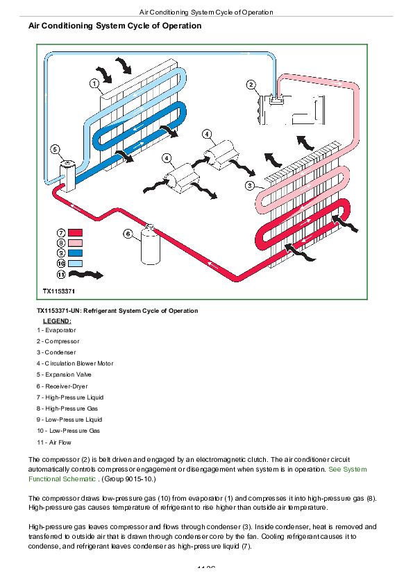
Air Conditioning System Cycle of Operation................1138
Group 10: System Diagrams................1135
Heating and Air Conditioning System Component Location................1141
Group 15: Diagnostic Information................1135
Air Conditioning System Does Not Operate................1135
Air Conditioning System Does Not Cool Interior of Cab................1135
Air Conditioning System Runs Constantly, Too Cold................1135
Heating System Does Not Operate................1135
Heating System Does Not Warm Interior of Cab................1135
Interior Windows Continue to Fog................1135
Group 25: Tests................1135
R134a Refrigerant Cautions and Proper Handling................1171
R134a Oil Charge Capacity................1172
R134a Refrigerant Charge Capacity................1173
Heater and Air Conditioner Operational Checks................1174
Air Conditioner Compressor Clutch Test................1178
R134a Refrigerant Leak Test................1179
R134a Refrigerant Hoses and Tubing Inspection................1180
Air Conditioner High/Low-Pressure Switch Test................1181
Air Conditioner Freeze Control Switch Test................1184
Air Conditioning System Test................1186
Operating Pressure Diagnostic Chart................1189
John Deere 210L Tractor Loader Diagnosis and Test Service Technical Manual (TM13473X19)


