John Deere 30G Excavator Diagnosis and Test Service Technical Manual (TM14234X19)
Catalog:
Model:
Complete Diagnosis & Tests Technical Manual with electrical wiring diagrams for John Deere 30G Excavator, with workshop information to maintain, diagnose, and rebuild like professional mechanics.
John Deere 30G Excavator workshop Diagnosis & Tests technical manual includes:
* Numbered table of contents easy to use so that you can find the information you need fast.
* Detailed sub-steps expand on repair procedure information
* Numbered instructions guide you through every repair procedure step by step.
* Troubleshooting and electrical service procedures are combined with detailed wiring diagrams for ease of use.
* Notes, cautions and warnings throughout each chapter pinpoint critical information.
* Bold figure number help you quickly match illustrations with instructions.
* Detailed illustrations, drawings and photos guide you through every procedure.
* Enlarged inset helps you identify and examine parts in detail.
TM14234X19 - John Deere 30G Excavator Technical Manual - Operation and Test.pdf
tm14234x28 - John Deere Excavatrice 30G.pdf
tm14234x63 - John Deere Excavadora 30G.pdf
PRODUCT DETAILS:
Total Pages: 780 pages
File Format: PDF (bookmarked, ToC, Searchable, Printable)
Category: Operation and Test
Language: English Spanish French
Published on 2019/12/30
TABLE OF CONTENTS
Section 9000: General Information................19
Group 01: Safety................19
Safety and Operator Convenience Features................23
Recognize Safety Information................25
Follow Safety Instructions................26
Operate Only If Qualified................27
Wear Protective Equipment................28
Avoid Unauthorized Machine Modifications................29
Control Pattern................30
Control Pattern Selector—If Equipped................31
Inspect Machine................32
Stay Clear of Moving Parts................33
Avoid High-Pressure Fluids................34
Avoid High-Pressure Oils................35
Work In Ventilated Area................36
Avoid Static Electricity Risk When Refueling................37
High Debris Applications................39
Prevent Fires................40
In Case of Machine Fire................41
Prevent Battery Explosions................42
Handle Chemical Products Safely................43
Handle Starting Fluid Safely................44
Decommissioning — Proper Recycling and Disposal of Fluids and Components................45
Prepare for Emergencies................46
Clean Debris from Machine................47
Add Cab Guarding for Special Uses................48
Use Steps and Handholds Correctly................49
Start Only From Operator's Seat................50
Use and Maintain Seat Belt................51
Prevent Unintended Machine Movement................52
Avoid Work Site Hazards................53
Keep Riders Off Machine................55
Avoid Backover Accidents................56
Avoid Machine Tip Over and Machine Damage................57
Use Special Care When Lifting Objects................59
Use Care When Swinging Machine................60
Operate Boom With Care................61
Avoid Power Lines................62
Inspect and Maintain ROPS................63
Travel Safely................64
Prevent Acid Burns................65
Add and Operate Attachments Safely................67
Park and Prepare for Service Safely................68
Service Machines Safely................69
Service Cooling System Safely................70
Remove Paint Before Welding or Heating................71
Make Welding Repairs Safely................72
Drive Metal Pins Safely................73
Use Proper Lifting Equipment................74
Safety Signs................75
Section 9001: Diagnostics................83
Group 10: Engine Control Unit (ECU) Diagnostic Trouble Codes................87
Engine Control Unit (ECU) Diagnostic Trouble Codes................87
000029.08 - Spare Accelerator Sensor Error (Pulse Communication) (P1227) (0001D-08)................83
000091.02 - Accelerator Sensor Intermittent Failure (P0124) (0005B-02)................83
000091.03 - Acceleration Sensor Error (High Voltage) (P0123) (0005B-03)................83
000091.04 - Acceleration Sensor Error (Low Voltage) (P0122) (0005B-04)................83
000100.01 - Oil Pressure Descend Error (P1198) (00064-01)................83
000100.04 - Oil Pressure Switch Error (P1192) (00064-04)................83
000110.00 - Cooling Water Temperature Rise Alarm (Overheat) (P0217) (0006E-00)................83
000110.02 - Cooling Water Temperature Sensor Intermittent Failure (P0119) (0006E-02)................83
000110.03 - Cooling Water Temperature Sensor Error (High Voltage) (P0118) (0006E-03)................83
000110.04 - Cooling Water Temperature Sensor Error (Low Voltage) (P0117) (0006E-04)................83
000158.00 - Power Supply Voltage Error (High Voltage) (P0563) (0009E-00)................83
000158.01 - Power Supply Voltage Error (Low Voltage) (P0562) (0009E-01)................83
000167.01 - Charge Alarm (P1568) (000A7-01)................83
000167.04 - Charge Switch Error (P1562) (000A7-04)................83
000190.00 - Overspeed Error (P0219) (000BE-00)................83
000628.02 - ECU Internal Flash ROM Error (Checksum B) (P1605) (00274-02)................83
000628.02 - ECU Internal Flash ROM Error (Checksum C) (P1606) (00274-02)................83
000628.12 - ECU Internal Flash ROM Error (Checksum A) (P0605) (00274-0C)................83
000630.02 - ECU Internal EEPROM Error (Checksum) (P1601) (00276-02)................83
000630.12 - ECU Internal EEPROM Error (Read/Write Error) (P0601) (00276-0C)................83
000638.02 - Engine Error (P1214) (0027E-02)................83
000638.03 - Rack Actuator Error (High Current) (P1213) (0027E-03)................83
000638.04 - Rack Actuator Error (Low Current) (P1212) (0027E-04)................83
000638.07 - Rack Actuator Mechanical Failure (P1211) (0027E-07)................83
000639.12 - CAN Communication Error (U0001) (0027F-0C)................83
001078.04 - Speed Sensor Error (P0340) (00436-04)................83
001079.02 - Sensor 5 V Intermittent Failure (P1644) (00437-02)................83
001079.03 - Sensor 5 V Error (High Voltage) (P0643) (00437-03)................83
001079.04 - Sensor 5 V Error (Low Voltage) (P0642) (00437-04)................83
001136.01 - ECU Temperature Rise Alarm (P0634) (00470-00)................83
001136.02 - ECU Temperature Sensor Intermittent Failure (P1664) (00470-02)................84
001136.03 - ECU Temperature Sensor Error (High Voltage) (P0669) (00470-03)................84
001136.04 - ECU Temperature Sensor Error (Low Voltage) (P0668) (00470-04)................84
001210.03 - Rack Position Sensor Error (High Voltage) (P1203) (004BA-03)................84
001210.04 - Rack Position Sensor Error (Low Voltage) (P1202) (004BA-04)................84
001485.04 - Main Relay Error (P0686) (005CD-04)................84
522241.02 - Rack Actuator Relay Intermittent Failure (P1224) (7F801-02)................84
522241.03 - Rack Actuator Relay Error B (P1223) (7F801-03)................84
522241.04 - Rack Actuator Relay Error A (P1222) (7F801-04)................84
522242.02 - CSD Solenoid Valve Intermittent Failure (P1244) (7F802-02)................84
522242.03 - CSD Solenoid Valve Error B (P1243) (7F802-03)................84
522242.04 - CSD Solenoid Valve Error A (P1242) (7F802-04)................84
522243.02 - Start Assist Relay Intermittent Failure (P1234) (7F803-02)................84
522243.03 - Start Assist Relay Error B (P1233) (7F803-03)................84
522243.04 - Start Assist Relay Error A (P1232) (7F803-04)................84
522251.03 - EGR Valve Error B (Step Motor A-Phase) (P1403) (7F80B-03)................84
522251.04 - EGR Valve Error A (Step Motor A-Phase) (P1402) (7F80B-04)................84
522252.03 - EGR Valve Error B (Step Motor B-Phase) (P1413) (7F80C-03)................84
522252.04 - EGR Valve Error A (Step Motor B-Phase) (P1412) (7F80C-04)................84
522253.03 - EGR Valve Error B (Step Motor C-Phase) (P1423) (7F80D-03)................84
522253.04 - EGR Valve Error A (Step Motor C-Phase) (P1422) (7F80D-04)................84
522254.03 - EGR Valve Error B (Step Motor D-Phase) (P1433) (7F80E-03)................84
522254.04 - EGR Valve Error A (Step Motor D-Phase) (P1432) (7F80E-04)................84
522314.00 - Abnormal Water Temperature (P1217) (7F84A-00)................84
522323.00 - Air Cleaner Clogging Alarm (P1101) (7F853-00)................84
522329.00 - Oil/Water Separator Alarm (P1151) (7F859-00)................84
522402.04 - Spare Speed Sensor Error (P1340) (7F8A2-04)................84
522727.12 - ECU Internal Sub CPU Error A (P1610) (7F9E7-0C)................84
522727.12 - ECU Internal Sub CPU Error B (P1611) (7F9E7-0C)................84
522727.12 - ECU Internal Sub CPU Error C (P1612) (7F9E7-0C)................84
522728.12 - ECU Internal Map Format Error (P1620) (7F9E8-0C)................84
Group 30: Monitor Controller (DSZ) Diagnostic Trouble Codes................150
Monitor Controller (DSZ) Diagnostic Trouble Codes................150
E:1100 - Engine Trouble Alarm................85
W:1100 - Engine Warning................85
W:1102 - Exhaust Filter Regeneration Request................85
W:1103 - Exhaust Filter Regeneration Inhibited Alarm................85
W:1104 - Intermediate Gas Temperature Sensor Error................85
W:1105 - Exhaust Filter Differential Pressure Sensor Error................85
W:1106 - Inlet Port Gas Temperature Sensor Error................85
W:1107 - Engine Injection Pressure Sensor Error................85
W:1108 - Exhaust Filter Gas Inlet Air Pressure Sensor Error................85
W:1109 - Engine Inlet Air Piping Abnormal Temperature................85
W:1110 - Air Heat Relay Error................85
W:1111 - Exhaust Filter Manual Regeneration Inhibited Alarm................85
W:1206 - Air Filter Restriction Alarm................85
W:1207 - Coolant Temperature Sensor Error................85
W:1208 - Engine Speed Sensor Error................85
W:1209 - Atmospheric Pressure Sensor Error................85
W:1210 - Water Separator Alarm................85
W:1211 - Ambient Air Temperature Sensor Error................85
W:1303 - Combustion Temperature Sensor Error................85
W:1304 - Engine Control Dial Error (CAN Signal)................85
W:1310 - CAN Communication Error................85
W:2201 - Overheat Alarm................85
W:2202 - Engine Oil Pressure Alarm................85
W:2304 - Fuel Sensor Error................85
W:2306 - Boom Bottom Pressure Sensor Error................85
W:2307 - Engine Control Dial Error (Analog Signal)................85
W:2310 - EEPROM Error................85
Section 9005: Operational Checkout Procedure................197
Group 10: Operational Checkout Procedure................197
Operational Checkout................249
Section 9010: Engine................300
Group 05: Theory of Operation................300
Yanmar Engine................316
Engine Fuel System Component Location................303
Engine Cooling System Component Location................305
Cold Weather Starting Aid................307
Engine Speed Control System Operation................308
Group 15: Diagnostic Information................300
Yanmar Engine................316
Group 20: Adjustments................300
Yanmar Engine................316
Group 25: Tests................300
Yanmar Engine................316
Section 9015: Electrical System................317
Group 05: System Information................317
Electrical Diagram Information................328
Group 10: System Diagrams................317
Explanation of Wire Markings................337
Fuse and Relay Specifications................338
System Functional Schematic, Wiring Diagrams, and Component Locations Master Legend................341
System Functional Schematic................344
Floor Harness (W1) Component Location................349
Floor Harness (W1) Wiring Diagram................351
Engine Harness (W2) Component Location................353
Engine Harness (W2) Wiring Diagram................356
Air Conditioner Harness (W3) Component Location................359
Air Conditioner Harness (W3) Wiring Diagram................361
Console Harness (W4) Component Location................362
Console Harness (W4) Wiring Diagram................363
Cab Harness (W5) Component Location................364
Cab Harness (W5) Wiring Diagram................365
Auto-Shutdown Harness (W6) Component Location................366
Auto-Shutdown Harness (W6) Wiring Diagram................367
Auxiliary Function Lever Harness (W7) Component Location................368
Auxiliary Function Lever Harness (W7) Wiring Diagram................369
Air Conditioner Compressor Harness (W8) Component Location................370
Air Conditioner Compressor Harness (W8) Wiring Diagram................371
Boom Work Light Harness (W9) Component Location................372
Boom Work Light Harness (W9) Wiring Diagram................373
Canopy Work Light Harness (W13) Component Location................374
Canopy Work Light Harness (W13) Wiring Diagram................375
Windshield Wiper Extension Harness (W16) Component Location................376
Windshield Wiper Extension Harness (W16) Wiring Diagram................377
Windshield Wiper Harness (W17) Component Location................378
Windshield Wiper Harness (W17) Wiring Diagram................379
Group 15: Sub-System Diagnostics................318
Controller Area Network (CAN) Theory of Operation................382
Starting and Charging Circuit Theory of Operation................384
Auto-Shutdown Circuit Theory of Operation................387
Engine Control Unit (ECU) Circuit Theory of Operation................389
Monitor Controller (DSZ) Circuit Theory of Operation................394
Pilot Shutoff Circuit Theory of Operation................398
Travel Speed Control and Alarm Circuit Theory of Operation................400
Windshield Wiper and Washer Circuit Theory of Operation................403
Lighting Circuit Theory of Operation................405
Heating and Air Conditioning Control Circuit Theory of Operation................407
Auxiliary Function Control Lever Circuit Theory of Operation................411
Group 16: Monitor Operation................318
Service Menu................415
Monitoring................417
Setting................419
Trouble Code Record................421
Group 20: References................318
Electrical Component Specifications................424
Reading Diagnostic Trouble Codes With Monitor Display................425
Service ADVISOR™ Diagnostic Application................427
Service ADVISOR™ Connection Procedure................428
Reading Diagnostic Trouble Codes with Service ADVISOR™ Diagnostic Application................430
Engine Speed Dial Remove and Install................433
Alternator Test................434
Electrical Component Checks................438
Battery Remove and Install................446
Monitor Controller (DSZ) Remove and Install................448
Monitor Controller (DSZ) Replacement Calibration................451
Engine Control Unit (ECU) Remove and Install................457
Engine Control Unit (ECU) Replacement Calibration................459
Fuel Pump Replacement Calibration................463
Yanmar Display Calibration Values Test................465
JDG1928 Interlock Switch................466
Section 9020: Power Train................467
Group 05: Theory of Operation................467
Track Adjuster and Recoil Spring Operation................470
Travel Gear Case Operation................472
Group 15: Diagnostic Information................467
Noisy or Loose Track Chain................467
Tight Track Chain................467
Frequent Track Chain Sag Adjustment Required................467
Excessive Oil Leakage From Front Idler, Track Rollers, or Carrier Rollers................467
“Popping” of Track................467
Individual Undercarriage Component Wear................467
Measure Swing Bearing Wear................482
Section 9025: Hydraulic System................486
Group 05: Theory of Operation................486
Hydraulic System Operation................490
Pilot System Operation................491
Pilot Pump and Filter Operation................492
Solenoid Valve Manifold Operation................493
Pilot Shutoff Solenoid Valve Operation................495
Travel Mode Solenoid Valve Operation................500
Pilot Pressure Regulating Valve Operation................503
Pilot Control Valve Operation................523
Control Lever Pattern Selector Operation................507
Travel Pilot Control Valve Operation................523
Pilot Operation of Control Valve Operation................523
Hydraulic Pump 1 and 2 Operation................514
Hydraulic Pump Regulator Operation................516
Hydraulic Pump 3 Operation................518
Air Conditioner Torque Control Solenoid Valve Operation—If Equipped................520
Control Valve Operation................523
Control Valve Check Valves Operation................538
Main Relief Valve Operation................542
Circuit Relief and Anticavitation Valve Operation................544
Swing Boom Make-Up Valve Operation................549
Flow Combiner Valve Operation................551
Auxiliary Function Control Valve Operation................555
Boom Reduced Leakage Valve Operation................558
Arm Regenerative Valve Operation................561
Swing Reduction Gear Case Operation................564
Swing Motor Operation................566
Swing Motor Crossover Relief Valve Operation................568
Swing Motor Crossover Relief Valve Cushion Valve Operation................571
Swing Motor Make-Up Check Valve Operation................572
Swing Motor Park Brake Release Circuit Operation................573
Center Joint Operation................576
Travel Motor and Park Brake Valve Operation................577
Travel Motor Speed Circuit Operation................583
Blade Circuit Operation................586
Auxiliary Selector Valve Operation................588
Hydraulic Cylinder Operation................590
Return Filter Operation................591
Group 15: Diagnostic Information................487
All Hydraulic Functions Slow................487
Hydraulic Oil Overheats................487
No Hydraulic Functions................487
Poor Combined Operation................487
All Functions Cannot Be Operated................487
Function Does Not Stop When Control Lever Released................487
Some Functions Cannot Be Operated, All Others Are Normal................487
Functions Move in Opposite Direction................487
Arm and Boom Functions Do Not Operate or Do Not Operate as Expected................487
All Dig Functions Slow or No Power................487
Some Dig Functions Slow (Not All)................487
Load Drifts Down When Control Lever is in Neutral Position................487
Load Falls When Control Valve is Actuated to Raise Load With Engine Running at Slow Idle................487
Arm In Speed Slow................487
Swing Speed Slow in Both Directions................487
Swing Speed Slow or Does Not Operate in One Direction................487
Upperstructure Drift With Swing Valve in Neutral................487
Swing Function Does Not Operate................487
Travel Park Brakes Do Not Apply................487
Track Will Not Move in One Direction................487
Track Will Not Move in Either Direction................487
Machine Mistracks at All Speeds in Both Directions................487
Slow Travel Speed or Low Power................487
Travel Speed Does Not Change to Slow Speed................487
Combined Travel and Dig Functions Slow or No Power................487
Travel is “Jerky”................487
Machine Will Not Hold Back and Park Brakes Engage and Disengage When Traveling Down an Incline................488
Machine Will Not Turn Smoothly in One Direction or Park Brake Grabs................488
Swing Boom Does Not Move or Moves Slowly................488
Blade Does Not Move or Moves Slowly................488
Hydraulic System Schematic................658
Hydraulic System Component Location................667
Pump 1, Pump 2, Pump 3, and Pilot Pump Line Connections................676
Control Valve Line Connections................677
Pilot Control Line Connections................678
Front Attachment Line Connections................680
Travel System Line Connections................681
Swing System Line Connections................682
Blade System Line Connections................683
Group 25: Tests................488
JT02156A Digital Pressure and Temperature Analyzer Installation................685
JT05800 Digital Thermometer Installation................686
General Hydraulic Oil Cleanup Procedure................687
Hydraulic Component Failure Cleanup Procedure................690
Hydraulic Oil Tank Pressure Release Procedure................693
Hydraulic System Warm-Up Procedure................695
Pilot Pressure Regulating Valve Test and Adjustment................697
Control Valve Spool Pilot Actuating Pressure Test................700
Hydraulic Pump 1, 2, and 3 Main Relief Valve Test and Adjustment................703
Circuit Relief and Anticavitation Valve Test and Adjustment................707
Swing Motor Crossover Relief Valve Test and Adjustment................712
Hydraulic Pump Flow Test................715
Swing Motor Leakage Test................720
Travel Motor Leakage Test................723
Air Conditioner Torque Control Solenoid Valve Test................726
Cylinder Drift Test—Boom, Arm, Bucket, and Blade................729
Section 9031: Heating and Air Conditioning................733
Group 05: Theory of Operation................733
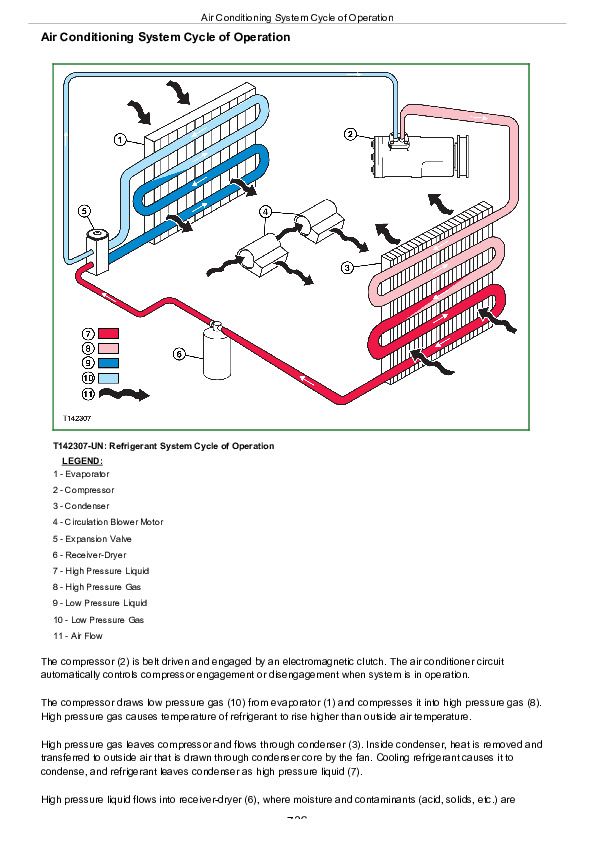
Air Conditioning System Cycle of Operation................736
Group 15: Diagnostic Information................733
Air Conditioning System Does Not Operate................733
No Air Flow From Heater and Air Conditioner Vents................733
Air Conditioning Does Not Cool Interior of Cab................733
Air Conditioning Runs Constantly, Too Cold................733
Interior Windows Continue to Fog Using Air Conditioner................733
Heater System Does Not Operate................733
Heater Does Not Warm Interior of Cab................733
Interior Windows Continue to Fog Using Heater................733
Heater and Air Conditioner Component Location................763
Group 25: Tests................733
R134a Refrigerant Cautions and Proper Handling................766
Heater and Air Conditioner Operational Checks................767
Refrigerant Leak Test................770
Air Conditioner Compressor Clutch Test................771
Refrigerant Hoses and Tubing Inspection................772
Air Conditioner Compressor Belt Check................773
R134a Air Conditioning System Test................774
Operating Pressure Diagnostic Chart................777
John Deere 30G Excavator Diagnosis and Test Service Technical Manual (TM14234X19)


