John Deere Excavator Logger 330LC, 370 Operation & Tests Manual Supplement (TM1910)
Catalog:
Model:
Complete Diagnostics, Operation & Tests Supplement with Electrical Wiring Diagrams for John Deere Excavator Logger 330LC, 370, with all the service information to maintain, diagnose, rebuild like professional mechanics.
John Deere Excavator Logger 330LC, 370 workshop Diagnosis & Tests Supplement includes:
* Numbered table of contents easy to use so that you can find the information you need fast.
* Detailed sub-steps expand on repair procedure information
* Numbered instructions guide you through every repair procedure step by step.
* Troubleshooting and electrical service procedures are combined with detailed wiring diagrams for ease of use.
* Notes, cautions and warnings throughout each chapter pinpoint critical information.
* Bold figure number help you quickly match illustrations with instructions.
* Detailed illustrations, drawings and photos guide you through every procedure.
* Enlarged inset helps you identify and examine parts in detail.
TM1910 - 330LC and 370 Excavator Logger Operation and Tests Supplement (S.N.081001-) Technical Manual.pdf
Total Pages: 556 pages
File Format: PDF (bookmarked, ToC, Searchable, Printable)
Category: Operation and Test
Language: English
Published on 2005/02/21
MAIN SECTIONS (SN. 081001-)
Foreword
Technical Information Feedback Form
General Information
Safety
General Specifications
Torque Values
Fuels and Lubricants
Operational Checkout Procedure
Operational Checkout Procedure
Electrical System
System Diagrams
Sub-System Diagnostics
Hydraulic System
Theory of Operation
Diagnostic Information
Tests
Air Conditioning System
Theory of Operation
System Operational Checks
Diagnostic Information
Adjustments
Tests
Table of Contents
Foreword
Technical Information Feedback Form
Section 9000: General Information
Group 01: Safety
John Deere Excavator Logger Safety Features
Recognize Safety Information
Understand Signal Words
Follow Safety Instructions
Inspect Machine
Use Handholds and Steps
Use Seat Belt
Maintain Seat Belt
Move and Operate Machine Safely
Operate Only From Operator's Seat
Secondary Exits
Operate Machine Safely
(Road Builder) Dig with Caution
Operate with Caution
Avoid Tipping
Avoid Power Lines
Drive Machine Safely
Beware of Exhaust Fumes
Park Machine Safely
Keep Riders Off Machine
Operate Attachment Safely
Keep the Operator Protective Structure (OPS) in Place
Handle Fluids Safely-Avoid Fires
Prepare for Emergencies
Handle Starting Fluid Safely
Clean Trash from Machine
Protect Against Flying Debris
Wear Protective Clothing
Protect Against Noise
Handle Chemical Products Safely
Warn Others of Service Work
Stay Clear of Moving Parts
Support Machine Properly
Service Cooling System Safely
Practice Safe Maintenance
Remove Paint Before Welding or Heating
Avoid Heating Near Pressurized Fluid Lines
Avoid High-Pressure Fluids
Prevent Battery Explosions
Clean the Machine Regularly
Store Attachments Safely
Dispose of Waste Properly
Group 02: General Specifications
330LC Log Loader With Logger Front Live Heel Grapple With 2921 mm (9 Ft 7 In.) Track Gauge and Forestry Cab-Specifications
330LC Log Loader With Logger Front B-N-T Grapple With 3100 mm (10 Ft 2 In.) Track Gauge, Rear Entry Cab and Heavy Duty Belly Pan-Specifications
370 Log Loader With Logger Front Live Heel Grapple With 3100 mm (10 Ft 2 In.) Track Gauge and Rear Entry Cab -Specifications
370 Road Builder With 2692 mm (8 Ft 10 In.) Track Gauge Specifications
330LC Log Loader Excavator Combo Front with Boom Cylinder Lift Adapter Live Heel Grapple, 4 m (13 Ft 1 In.) Arm and 2692 mm (8 Ft 10 In.) Track Gauge Working Ranges
330LC Log Loader Excavator Combo Front with Boom Cylinder Lift Adapter Live Heel Grapple, 3.2 m (10 Ft 6 In.) Arm and 2692 mm (8 Ft 10 In.) Track Working Ranges
330LC Log Loader Logger Front Live Heel Grapple with Rear Entry Cab Working Ranges
330LC Log Loader Logger Front B-N-T Grapple Working Ranges
370LC Log Loader Excavator Combo Front with Boom Cylinder Lift Adapter Live Heel Grapple, 4 m (13 Ft 1 In.) Arm and 2692 mm (8 Ft 10 In.) Track Gauge with Forestry Cab Working Ranges
370 Log Loader Excavator Combo Front with Boom Cylinder Lift Adapter Live Heel Grapple, 32 m (10 Ft 6 In.) Arm and 2692 mm (8 Ft 10 In.) Track Gauge with Forestry Cab Working Ranges
370 Log Loader Logger Front Live Heel Grapple Working Ranges
330LC Road Builder Working Ranges
370 Road Builder Working Ranges
330LC/370 Excavator Logger Engine Specifications
330LC and 370 Drain and Refill Capacities
Lift Capacity-330LC Logger Live Heel Grapple With 2921 mm (9 Ft 7 In.) Track Gauge and Rear Entry or Forestry Cab
Lift Capacity-330LC Logger Live Heel Grapple With 3100 mm (10 Ft 2 In.) Track Gauge and Rear Entry or Forestry Cab
Lift Capacity-330LC Logger Butt-N-Top Grapple With 2921 mm (9 Ft 7 In.) Track Gauge and Forestry Cab
Lift Capacity-330LC Logger Butt-N-Top Grapple With 3100 mm (10 Ft 2 In.) Track Gauge and Rear Entry or Forestry Cab
Lift Capacity-330LC Logger Road Builder With 2692 mm (8 Ft 10 In.) Track Gauge, 1179 kg (2,600 lb) Bucket
Lift Capacity-370 Logger Live Heel Grapple With 3100 mm (10 Ft 2 In.) Track Gauge and Rear Entry or Forestry Cab
Lift Capacity-370 Logger Butt-N-Top Grapple With 3100 mm (10 Ft 2 In.) Track Gauge and Rear Entry or Forestry Cab
Lift Capacity-370 Logger Road Builder With 2591 mm (8 Ft 10 in.) Track Gauge, 1179 kg (2,600 lb) Bucket
Group 03: Torque Values
Unified Inch Bolt and Cap Screw Torque Values
Metric Bolt and Cap Screw Torque Values
Additional Metric Cap Screw Torque Values
Check Oil Lines and Fittings
Service Recommendations for O-Ring Boss Fittings
Service Recommendations for Flat Face O-Ring Seal Fittings
Service Recommendations for 37° Flare and 30° Cone Seat Connectors
Service Recommendations For Flared Connections-Straight or Tapered Threads
Service Recommendations For Inch Series Four Bolt Flange Fittings
Service Recommendations for Metric Series Four Bolt Flange Fitting
Group 04: Fuels and Lubricants
Diesel Fuel
Dieselscan Fuel Analysis
Lubricity Of Diesel Fuels
Low Sulfur Diesel Fuel Conditioner
Diesel Fuel Storage
Fuel Tank
Do Not Use Galvanized Containers
Diesel Engine Oil
Hydraulic Oil
Cab and Riser Tilt Power Pack Oil
Swing Gearbox, Propel Gearbox and Pump Gearbox Oils
Track Roller, Front Idler, and Carrier Roller Oil
Track Adjuster, Working Tool Pivot, Swing Bearing, and Swing Bearing Gear Grease
Oil Filters
Lubricant Storage
Alternative and Synthetic Lubricants
Mixing of Lubricants
Section 9005: Operational Checkout Procedure
Group 10: Operational Checkout Procedure
Operational Checkout
Section 9015: Electrical System
Group 10: System Diagrams
Replacing Fuses Rear Entry Cab
Replacing Fuses-Forestry and Road Builder Cab
Fuse (Blade-Type) Color Codes
Functional Schematic and Component Location Legend
System Functional Schematic Section Legend
System Functional Schematic (SE25-SE29)
System Functional Schematic (SE30-SE34)
System Functional Schematic (SE35-SE39)
System Functional Schematic (SE40, SE41)
System Functional Schematic ( SE42, SE43)
Rear Entry Cab Component Location
Forestry Cab Component Location
Road Builder Cab Component Location
Live Heel Grapple Frame Component Location
Butt-N-Top Grapple Frame Component Location
Road Builder Frame Component Location
Road Builder Combo Machine Component Location
Load Center Harness Live Heel Grapple (W15) (Rear Entry Cab)
Fuse Block Live Heel Grapple (W15) (Rear Entry Cab)-(Continued)
Load Center Harness Butt-N-Top Grapple/Valve in Head (W16) (Rear Entry Cab)
Fuse Block Butt-N-Top Grapple/Valve in Head (W16) (Rear Entry Cab)-(Continued)
Load Center Sub Harness (W17) (Rear Entry Cab)
Upper Cab Harness (W18) (Rear Entry Cab)
Cab Rear Light Extension Harness (W19) (Rear Entry Cab)
Cab Rear Work Light Harness (W20)
Front Work Light Harness (W21)
Dome Light Harness (W22) (Rear Entry Cab)
Right Hand Console Harnesses (W23)
Left Hand Console Harnesses (W24)
Butt-N-Top Joystick (W25)
Live Heel Grapple Joystick (W26)
Engine Harness Extension Harness (W27) (Forestry And Rear Entry Cab)
Engine Harness Extension Harness Detail “A & B” (W27)
Riser Light Harness (W28) (Rear Entry Cab)
Heater Control Harness (W29) (Rear Entry Cab)
Heater/Air Conditioner Harness (W30) (Rear Entry Cab)
Air Tank Pressure Switch Harness (W31) (Rear Entry Cab)
Key Switch Extension Harness (W32) (Rear Entry Cab)
Load Center to Boom Harness (W33) (Valve in Head Function Only)
Boom Harness (W34, W51)
Grapple Harness (W35, W52)
Suppression Diode Harness (W36) (Valve in Head Function)
Cab Power Tilt Harness (W37)
Driving Light Harness (W38)
Solenoid Pigtail Harness (W39)
Boom Light Harness (W41)
Machine #10 Harness (W42)
Machine #10 Riser Harness (W43)
Arm Work Light Harness (W44)
Cab Power Tilt Switch Harness W45
Load Center Harness Live Heel Grapple (W47) (Forestry and Road Builder Cab)
Load Center Harness Butt-N-Top Grapple/Valve in Head (W48) (Forestry and Road Builder Cab)
Upper Cab Harness (W49) (Forestry and Road Builder Cab)
Boom Light Harness (W50) (Road Builder Frame)
Wiper Extension Harness (W53) (Forestry Cab)
Group 15: Sub-System Diagnostics
Power Circuit Operational Information
Power Circuit Theory of Operation
Power Circuit Schematic
Live Heel Grapple/Thumb Joystick Controller Circuit
Live Heel Grapple/ Thumb Joystick Controller Circuit Schematic
Butt-N-Top Grapple/ Valve in Head (Right and Left) Joystick Controller Circuit
Butt-N-Top Grapple/Valve in Head (Left and Right) Joystick Controller Circuit Schematic
Work and Drive Light Circuit Operational Information
Work and Drive Light Circuit Theory of Operation
Work and Drive Light Circuit Schematic
Windshield Wiper Circuit Operational Information
Windshield Wiper Circuit (Rear Entry Cab) Theory of Operation
Windshield Wiper Circuit (Rear Entry Cab) Schematic
Windshield Wiper Circuit (Road Builder) Theory of Operation
Windshield Wiper Circuit Road Builder Cab Schematic
Cab Tilt Circuit Theory of Operation
Cab Tilt Circuit Schematic
Accessory Circuits Operational Information
Accessory Circuits Theory of Operation
Accessory Circuits Schematic
Monitor Circuits Theory of Operation
Monitor Circuits Schematic
Air Horn/Air Compressor Circuits Theory of Operation (Rear Entry Cab)
Air Horn/Air Compressor Circuits Schematic
Hydraulic Oil Tank Pressure Dump Circuits Theory of Operation (Optional)
Hydraulic Oil Tank Pressure Dump Circuits Schematic
Hydraulic Oil Tank Pressure Dump
12 Volt Accessory Circuits Theory of Operation
12 Volt Accessory Circuits Schematic
Section 9025: Hydraulic System
Group 05: Theory of Operation
Live Heel Grapple Hydraulic System Diagram
Thumb Hydraulic System Diagram
Articulated/Butt-N-Top Grapple Hydraulic System Diagram
Live Heel Grapple Rotate and Pilot Pump Operation
Proportional Solenoid Valve Manifold Operation
330LC/370 Live Heel Grapple-Grapple Open Hydraulic Circuit Schematic
330LC/370 Live Heel Grapple-Grapple Close Hydraulic Circuit Schematic
330LC/370 Live Heel Grapple-Grapple Rotate Clockwise Hydraulic Circuit Schematic
330LC/370 Live Heel Grapple-Grapple Rotate Counterclockwise Hydraulic Circuit Schematic
330LC/370 Road Builder-Thumb In Hydraulic Circuit Schematic
330LC/370 Road Builder-Thumb Out Hydraulic Circuit Schematic
330LC/370 Articulated/Butt-N-Top Grapple Auxilary Directional Control Valve Hydraulic Circuit
330LC/370 Butt-N-Top Grapple Float Solenoid Valve Hydraulic Circuit
330LC/370 Live Heel Grapple Control Valve Hydraulic Circuit Schematic
330LC/370 Butt-N-Top Grapple Control Valve Circuit Schematic
Group 15: Diagnostic Information
330LC/370 Live Heel Grapple Hydraulic System Component Location
330LC/370 Butt-N-Top Grapple Hydraulic System Component Location
Pilot Circuit for Controllers Schematic-Forestry Machines with Butt-N-Top Grapple Logging Front
Pilot Circuit for Controllers Schematic-Forestry Machines with Excavator Front
Pilot Circuit for Controllers Schematic-Forestry Machines with Live Heel Grapple Logging Front
Group 25: Tests
330LC/370 Hydraulic Oil Cleanup Procedure Using Portable Filter Caddy
Cycle Time Test-330LC/370 Logger
Circuit Relief Valve Test and Adjustment-330LC/370 Logger
Live Heel Grapple Rotate Pump Flow Test
Cylinder Drift Test-Boom and Arm
Section 9031: Air Conditioning System
Group 05: Theory of Operation
Forestry and Road Builder Cab Heater and Air Conditioner Circuit Operational Information
Rear Entry Cab Heater and Air Conditioner Operational Information
Rear Entry Cab Heater and Air Conditioner Circuit Theory of Operation
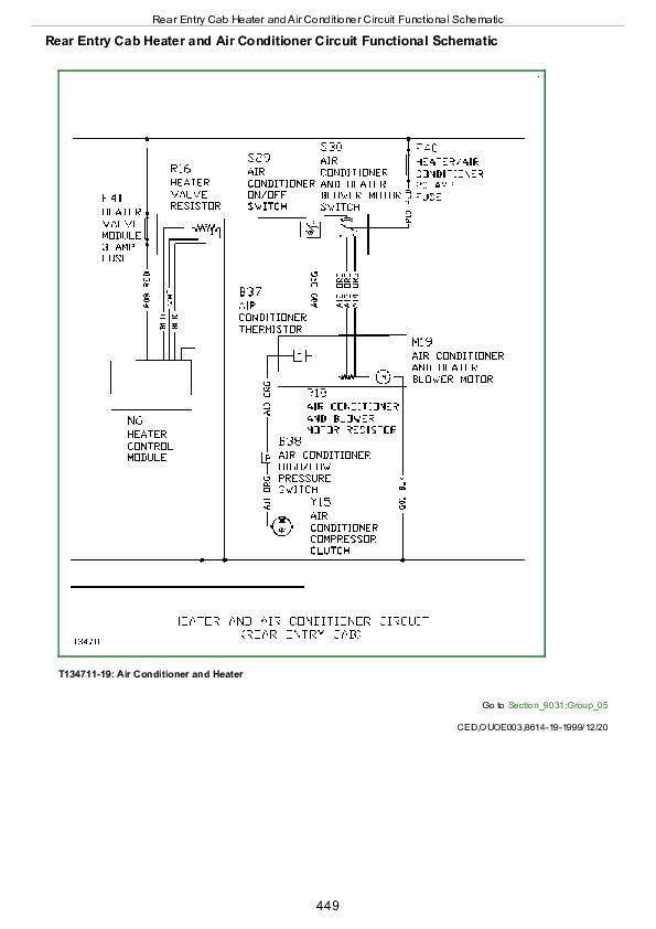
Rear Entry Cab Heater and Air Conditioner Circuit Functional Schematic
Group 10: System Operational Checks
Rear Entry Cab Heating and Air Conditioning Operational Checks
Group 15: Diagnostic Information
Diagnose Air Conditioning Electrical Malfunctions (Rear Entry Cab)
Rear Entry Cab Air Conditioner Harness Component Location
Group 20: Adjustments
Charge R134a System
Group 25: Tests
High and Low Pressure Switch Test (Rear Entry Cab)
John Deere Excavator Logger 330LC, 370 Operation & Tests Manual Supplement (TM1910)


