John Deere XCG 330LC-8B Excavator Technical Manual (Operation and Test) (TM11585)
Catalog:
Model:
Complete Operation and Test Technical manual with electrical wiring diagrams for John Deere / XCG Excavators 330LC-8B, with all the workshop information to maintain, diagnose, and rebuild like professional mechanics.
John Deere / XCG Excavators 330LC-8B workshop Operation and Test Service manual includes:
* Numbered table of contents easy to use so that you can find the information you need fast.
* Detailed sub-steps expand on repair procedure information
* Numbered instructions guide you through every repair procedure step by step.
* Troubleshooting and electrical service procedures are combined with detailed wiring diagrams for ease of use.
* Notes, cautions and warnings throughout each chapter pinpoint critical information.
* Bold figure number help you quickly match illustrations with instructions.
* Detailed illustrations, drawings and photos guide you through every procedure.
* Enlarged inset helps you identify and examine parts in detail.
TM11585 - John Deere XCG 330LC-8B Excavator Technical Manual (Operation and Test).pdf
Total Pages: 816 pages
File Format: PDF (bookmarked, ToC, Searchable, Printable)
Language: English
MAIN SECTIONS
Foreword
General Information
Safety
Diagnostics
Advanced Display Unit (ADU) Diagnostic Trouble Codes
Flex Load Controller (FLC) Diagnostic Trouble Codes
Sealed Switch Module (SSM) Diagnostic Trouble Codes
Operational Checkout Procedure
Operational Checkout Procedure
Engine
Theory of Operation
Diagnostic Information
Adjustments
Tests
Electrical System
System Information
System Diagrams
Sub-System Diagnostics
Monitor Operation
References
Power Train
Theory of Operation
Diagnostic Information
Hydraulic System
Theory of Operation
Diagnostic Information
Tests
Heating and Air Conditioning
Theory of Operation
Diagnostic Information
Tests
Dealer Fabricated Tools
TABLE OF CONTENTS
Section 9000: General Information............15
Group 01: Safety............15
Recognize Safety Information............17
Follow Safety Instructions............18
Operate Only If Qualified............19
Wear Protective Equipment............20
Avoid Unauthorized Machine Modifications............21
Add Cab Guarding for Special Uses............22
Inspect Machine............23
Stay Clear of Moving Parts............24
Avoid High-Pressure Fluids............25
Avoid High-Pressure Oils............26
Work In Ventilated Area............27
Prevent Fires............28
Prevent Battery Explosions............29
Handle Chemical Products Safely............30
Dispose of Waste Properly............31
Prepare for Emergencies............32
Use Steps and Handholds Correctly............33
Start Only From Operator's Seat............34
Use and Maintain Seat Belt............35
Prevent Unintended Machine Movement............36
Avoid Work Site Hazards............37
Keep Riders Off Machine............39
Avoid Backover Accidents............40
Avoid Machine Tip Over............41
Do Not Lift Objects............43
Add and Operate Attachments Safely............44
Park and Prepare for Service Safely............45
Service Cooling System Safely............46
Remove Paint Before Welding or Heating............47
Make Welding Repairs Safely............48
Drive Metal Pins Safely............49
Section 9001: Diagnostics............50
Group 10: Advanced Display Unit (ADU) Diagnostic Trouble Codes............50
000158.03 - Key Switch Voltage Voltage High............50
000158.04 - Key Switch Voltage Voltage Low............50
000168.03 - System Voltage Voltage High............50
000168.04 - System Voltage Voltage Low............50
000442.00 - Display Temperature Very High............50
000442.01 - Display Temperature Very Low............50
001491.11 - LCD Backlight Failure Cause Unknown............50
003597.02 - 5.0 V Power Supply Intermittent............50
003598.02 - 1.5 V Power Supply Intermittent............50
003599.02 - 3.3 V Power Supply Intermittent............50
523436.14 - ADU Watchdog See Manual............50
523438.31 - Memory Error No Information............50
523651.02 - Memory Stack Overflow Intermittent............50
523773.03 - CAN High Voltage High............50
523773.04 - CAN High Voltage Low............50
523774.03 - CAN Low Voltage High............50
523774.04 - CAN Low Voltage Low............50
524076.10 - Info Button Stuck Bad Rate of Change............50
524077.10 - Back Button Stuck Bad Rate of Change............50
524078.10 - Menu Button Stuck Bad Rate of Change............50
524080.10 - Down Arrow Button Stuck Bad Rate of Change............50
524082.10 - Up Arrow Button Stuck Bad Rate of Change............50
Group 20: Flex Load Controller (FLC) Diagnostic Trouble Codes............50
000096.03 - Fuel Level Sensor Voltage High............50
000096.04 - Fuel Level Sensor Voltage Low............50
000100.01 - Engine Oil Pressure Very Low............50
000100.03 - Engine Oil Pressure Voltage High............50
000107.00 - Engine Air Filter Restriction Very High............50
000107.03 - Engine Air Filter Restriction Voltage High............50
000110.00 - Engine Coolant Temperature Very High............50
000110.04 - Engine Coolant Temperature Voltage Low............50
000167.03 - Alternator Output Voltage High............51
000167.04 - Alternator Output Voltage Low............51
000190.08 - Engine Speed Sensor Abnormal Frequency Input Data............51
000632.06 - Engine Fuel Shutoff Current Above Normal............51
000638.04 - Throttle Actuator Low Voltage............51
000638.07 - Throttle Actuator Mechanical Failure or Calibration............51
000638.09 - Throttle Actuator Abnormal Update Rate............51
000638.12 - Throttle Actuator Bad Device or Component............51
000638.13 - Throttle Actuator Out of Calibration............51
000676.05 - Glow Plug Relay Current Low............51
000676.06 - Glow Plug Relay Current High............51
000677.05 - Engine Starter Relay Current Below Normal............51
000677.06 - Engine Starter Relay Current Above Normal............51
000742.05 - High Low Travel Speed Solenoid Current Below Normal............51
000742.06 - High Low Travel Speed Solenoid Current Above Normal............51
000882.05 - License Plate Light Current Below Normal............51
000882.06 - License Plate Light Current Above Normal............51
001041.04 - Start Signal Indicator Voltage Low............51
001638.00 - Hydraulic Oil Temperature Very High............51
001638.04 - Hydraulic Oil Temperature Voltage Low............51
001713.01 - Hydraulic Oil Filter Restriction Very Low............51
001713.03 - Hydraulic Oil Filter Switch Voltage High............51
002040.09 - ADU CAN Communication Bad Update Rate............51
002141.09 - SSM CAN Communication Bad Update Rate............51
002177.09 - Throttle Actuator CAN Communication Bad Update Rate............51
002354.05 - Right Frame Worklight Current Below Normal............51
002354.06 - Right Frame Worklight Current Above Normal............51
002386.05 - Rotary Beacon Light Current Below Normal............51
002386.06 - Rotary Beacon Light Current Above Normal............51
002400.05 - Boom Worklight Current Below Normal............51
002400.06 - Boom Worklight Current Above Normal............51
003509.03 - Sensor Supply 1 Voltage High............51
003509.04 - Sensor Supply 1 Voltage Low............51
003510.03 - Sensor Supply 2 Voltage High............52
003510.04 - Sensor Supply 2 Voltage Low............52
003511.03 - Sensor Supply 3 Voltage High............52
003511.04 - Sensor Supply 3 Voltage Low............52
003512.03 - Sensor Supply 4 Voltage High............52
003512.04 - Sensor Supply 4 Voltage Low............52
520544.01 - GPS Anti-Vandalism Switch Voltage Very Low............52
520544.03 - GPS Anti-Vandalism Switch Voltage High............52
520545.05 - Pressure Boost Solenoid Current Low............52
520545.06 - Pressure Boost Solenoid Current High............52
520546.04 - Pilot Enable Switch Voltage Low............52
520547.04 - Pressure Boost Switch Voltage Low............52
520548.04 - Travel Pressure Switch Voltage Low............52
520549.04 - Boom Pressure Switch Voltage Low............52
520551.06 - Travel Alarm Current High............52
522141.05 - Main Pump Solenoid Current Below Normal............52
522141.06 - Main Pump Solenoid Current Above Normal............52
522427.04 - Front Wiper Park Voltage Low............52
522429.05 - Pilot Enable Solenoid Current Below Normal............52
522429.06 - Pilot Enable Solenoid Current Above Normal............52
522434.05 - Front Wiper Low Speed Current Low............52
522434.06 - Front Wiper Low Speed Current High............52
522435.05 - Front Wiper High Speed Current Low............52
522435.06 - Front Wiper High Speed Current High............52
522797.05 - Front Washer Pump Current Low............52
522797.06 - Front Washer Pump Current High............52
522944.05 - Left Front Cab Worklight Current Below Normal............52
522944.06 - Left Front Cab Worklight Current Above Normal............52
522945.05 - Right Front Cab Worklight Current Below Normal............52
522945.06 - Right Front Cab Worklight Current Above Normal............52
523440.04 - Unswitched Power Voltage Low............52
524089.03 - P1 Pump Pressure Sensor Voltage High............52
524089.04 - P1 Pump Pressure Sensor Voltage Low............52
524090.03 - P2 Pump Pressure Sensor Voltage High............53
524090.04 - P2 Pump Pressure Sensor Voltage Low............53
524096.02 - Throttle Dial Bad Input Data............53
Group 30: Sealed Switch Module (SSM) Diagnostic Trouble Codes............53
000629.12 - Controller Fault............53
002033.09 - FLC CAN Communication Bad Update Rate............53
520752.04 - Auto Idle Button Stuck............53
520752.09 - Auto Idle Button Bad Update Rate............53
520753.04 - Hydraulic Power Button Stuck............53
520753.09 - Hydraulic Power Button Bad Update Rate............53
520754.04 - Unused Button 19 Stuck............53
520754.09 - Unused Button 19 Bad Update Rate............53
520755.04 - Unused Button 20 Stuck............53
520755.09 - Unused Button 20 Bad Update Rate............53
523335.04 - Travel Alarm Cancel Button Stuck............53
523335.09 - Travel Alarm Cancel Button Bad Update Rate............53
523336.04 - Travel Setting Button Stuck............53
523336.09 - Travel Setting Button Bad Update Rate............53
523338.04 - Unused Button 23 Stuck............53
523338.09 - Unused Button 23 Bad Update Rate............53
523339.04 - Unused Button 22 Stuck............53
523339.09 - Unused Button 22 Bad Update Rate............53
523340.04 - Unused Button 21 Stuck............53
523340.09 - Unused Button 21 Bad Update Rate............53
523849.04 - Unused Button 16 Stuck............53
523849.09 - Unused Button 16 Bad Update Rate............53
523850.04 - Unused Button 15 Stuck............53
523850.09 - Unused Button 15 Bad Update Rate............53
523852.04 - Unused Button 14 Stuck............53
523852.09 - Unused Button 14 Bad Update Rate............53
523854.04 - Front Washer Button Stuck............53
523854.09 - Front Washer Button Bad Update Rate............53
523855.04 - Front Wiper Button Stuck............53
523855.09 - Front Wiper Button Bad Update Rate............54
523856.04 - Unused Button 11 Stuck............54
523856.09 - Unused Button 11 Bad Update Rate............54
523857.04 - Unused Button 10 Stuck............54
523857.09 - Unused Button 10 Bad Update Rate............54
523858.04 - Boom Worklight Button Stuck............54
523858.09 - Boom Worklight Button Bad Update Rate............54
523860.04 - Cab Front Worklight Button Stuck............54
523860.09 - Cab Front Worklight Button Bad Update Rate............54
523861.04 - Front Frame Worklight Button Stuck............54
523861.09 - Front Frame Worklight Button Bad Update Rate............54
523862.04 - Unused Button 6 Stuck............54
523862.09 - Unused Button 6 Bad Update Rate............54
523863.04 - Unused Button 5 Stuck............54
523863.09 - Unused Button 5 Bad Update Rate............54
523864.04 - Unused Button 4 Stuck............54
523864.09 - Unused Button 4 Bad Update Rate............54
523865.04 - Rotary Beacon Button Stuck............54
523865.09 - Rotary Beacon Button Bad Update Rate............54
523867.04 - Unused Button 2 Stuck............54
523867.09 - Unused Button 2 Bad Update Rate............54
523868.04 - Unused Button 1 Stuck............54
523868.09 - Unused Button 1 Bad Update Rate............54
Section 9005: Operational Checkout Procedure............379
Group 10: Operational Checkout Procedure............379
Operational Checkout Procedure............379
Section 9010: Engine............406
Group 05: Theory of Operation............406
Engine Component Location............411
Engine Fuel System Operation............415
Start Aid Operation............416
Engine Speed Control System Operation............417
Group 15: Diagnostic Information............406
Isuzu AA-6HK1XQP Engine............420
Engine Cranks But Will Not Start............406
Engine Does Not Stop With Key Switch............406
Group 20: Adjustments............406
Engine Speed Control Linkage Check and Adjustment............424
Fuel Shut-Off Actuator Adjustment............425
Group 25: Tests............406
Engine Speed Test............428
Clamp-On Tachometer Installation............429
Section 9015: Electrical System............430
Group 05: System Information............430
Electrical Diagram Information............436
Electrical Schematic Symbols............440
Group 10: System Diagrams............430
Fuse and Relay Specifications............446
System Functional Schematic, Component Location, and Wiring Diagram Master Legend............449
System Functional Schematic............453
Left Frame Harness (W10) Component Location............457
Left Frame Harness (W10) Wiring Diagram............459
Middle Frame Harness (W11) Component Location............461
Middle Frame Harness (W11) Wiring Diagram............466
Right Frame Harness (W12) Component Location............468
Right Frame Harness (W12) Wiring Diagram............470
Load Center Harness (W13) Component Location............471
Load Center Harness (W13) Wiring Diagram............473
Cab Harness (W14) Component Location............475
Cab Harness (W14) Wiring Diagram............477
Right Console Harness (W15) Component Location............478
Right Console Harness (W15) Wiring Diagram............479
Cab Roof Harness (W16) Component Location............480
Cab Roof Harness (W16) Wiring Diagram............482
Boom Light Harness (W17) Component Location............483
Boom Light Harness (W17) Wiring Diagram............484
Diesel Fired Coolant Heater Harness (W18) Component Location............485
Diesel Fired Coolant Heater Harness (W18) Wiring Diagram............487
Group 15: Sub-System Diagnostics............430
Controller Area Network (CAN) Theory of Operation............490
Starting and Charging Circuit Theory of Operation............492
Flex Load Controller (FLC) Circuit Theory of Operation............495
Advanced Display Unit (ADU) Circuit Theory of Operation............500
Fuel Shutoff Actuator Theory of Operation............502
Group 16: Monitor Operation............431
Advanced Display Unit (ADU)—Service Mode............507
Advanced Display Unit (ADU)—Clear Codes............509
Advanced Display Unit (ADU)—Enable Options............510
Advanced Display Unit (ADU)—Throttle Actuator Cal............511
Advanced Display Unit (ADU)—Telematic............512
Advanced Display Unit (ADU) Screen is Blank Diagnostic Procedure............431
Group 20: References............431
Fuse and Relay Test............520
Electrical Component Checks............524
Electrical Component Specifications............529
Solenoid Test............431
Alternator Test............540
Engine Speed Control Actuator Calibration............542
Fuel Shut-Off Actuator Check............543
Controller Area Network (CAN) Circuit Test............548
Replace DEUTSCH DEUTSCH is a trademark of the Deutsch Co. Connectors............431
Replace DEUTSCH DEUTSCH is a trademark of Deutsch Co. Rectangular or Triangular Connectors............431
Install DEUTSCH DEUTSCH is a trademark of the Deutsch Co. Contact............431
Replace WEATHER PACK WEATHER PACK is a trademark of Packard Electric. Connector............431
Install WEATHER PACK WEATHER PACK is a trademark of Packard Electric. Contact............431
Replace (Pull Type) Metri-Pack™ Connectors............566
Replace (Push Type) Metri-Pack™ Connectors............568
Replace CINCH CINCH is a trademark of the Cinch Co. Connectors............431
Install CINCH CINCH is a trademark of the Cinch Co. Contact............431
Repair 32 and 48 Way CINCH CINCH is a trademark of the Cinch Co. Connectors............431
Remove Connector Body from Blade Terminals............577
Section 9020: Power Train............578
Group 05: Theory of Operation............578
Track Adjuster and Recoil Spring Operation............580
Travel Gearbox Operation............581
Group 15: Diagnostic Information............578
Noisy or Loose Track Chain............578
Tight Track Chain............578
Frequent Track Tension Adjustment Required............578
Excessive Oil Leakage From Front Idler, Track Rollers or Carrier Rollers............578
Bent Track Shoes............578
Section 9025: Hydraulic System............595
Group 05: Theory of Operation............595
Hydraulic System Operation............599
Pilot System Operation............600
Pilot Pump Operation............601
Pilot Enable Solenoid Valve Operation............602
Pilot Control Valve Operation............622
Travel Pilot Control Valve Operation............622
Pilot Operation of Control Valve Operation............622
Pilot Accumulator Manifold Operation............608
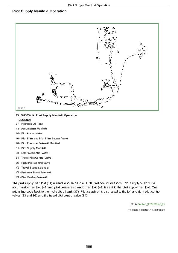
Pilot Supply Manifold Operation............609
Pilot Distribution Manifold Operation............610
Pump 1 and Pump 2 Operation............612
Pump 1 and Pump 2 Regulator Operation............614
Control Valve Operation............622
Control Valve Check Valves Identification and Operation............635
Main Relief Valve Circuit Operation............638
Circuit Relief and Anticavitation Valve Operation............640
Flow Control Valve Operation............642
Flow Combiner Valve Operation............644
Arm Regenerative Valve Circuit Operation............646
Boom and Arm Reduced Leakage Valves Operation............648
Swing Reduction Gear Case Operation............650
Swing Motor, Crossover Relief Valve, and Make-Up Check Valve Operation............652
Swing Motor Park Brake Release Circuit Operation............654
Rotary Manifold Operation............655
Travel Motor and Park Brake Valve Operation............657
Travel Motor Speed Circuit Operation............658
Cylinder Operation............659
Return Filter Operation............660
Group 15: Diagnostic Information............595
All Hydraulic Functions Slow............595
Hydraulic Oil Overheats............595
No Hydraulic Functions............596
Poor Combined Operation............596
Function Does Not Stop When Control Lever Released............596
Some Functions Cannot Be Operated, All Others Are Normal............596
Some Functions Slow............596
Function Moves in Opposite Direction............596
Load Drifts Down When Control Valve Is In Neutral Position............596
Load Falls When Control Valve Is Actuated To Raise Load With Engine Running at Slow Idle............596
H (high power) Function Does Not Operate, S (standard power) and L (low power) Mode Is Normal............596
Swing Speed Slow In Both Directions............596
Swing Speed Slow or Does Not Operate In One Direction............596
Upperstructure Drift With Swing Valve In Neutral............596
Swing Function Does Not Operate............596
Travel Park Brakes Do Not Apply............596
Track Will Not Move In One Direction............596
Track Will Not Move In Either Direction............596
Machine Mistracks at All Speeds In Both Directions............596
Slow Travel Speed or Low Power............596
Travel Is "Jerky"............596
Machine Will Not Hold Back and Park Brakes Engage and Disengage When Traveling Down an Incline............596
Machine Will Not Turn Smoothly In One Direction or Park Brake Grabs............596
Pump 1, Pump 2, and Pilot Pump Line Identification............722
Control Valve Line Identification............724
Swing Motor Line Identification............728
Pilot Control Valve-to-Pilot Distribution Manifold Component Location—Excavator Pattern............729
Pilot Control Valve-to-Pilot Distribution Manifold Component Location—Backhoe Pattern............731
Pilot Distribution Manifold to Control Valve Line Connection............733
Travel Hydraulic System Line Connections............747
Hydraulic System Schematic............736
Hydraulic System Component Location............745
Hydraulic System Line Connections............747
Group 25: Tests............596
JT05800 Digital Thermometer Installation............749
JT02156A Digital Pressure/Temperature Analyzer Installation............750
Hydraulic Oil Cleanup Procedure............751
Hydraulic Oil Tank Pressure Release Procedure............752
Hydraulic Oil Warmup Procedure............753
Pilot Pressure Regulating Valve Test and Adjustment............755
Control Valve Spool Actuating Pilot Pressure Test............757
Pressure Boost Solenoid Valve Test............760
Travel Speed Solenoid Valve Test and Adjustment............762
Pump Control Pilot Pressure Signal Test............764
System Relief Valve Test and Adjustment............767
Circuit Relief Valve Test and Adjustment............771
Swing Motor Crossover Relief Valve Test and Adjustment............777
Travel Motor Crossover Relief Valve Test and Adjustment............780
Pump Regulator Test and Adjustment—Minimum Flow............783
Pump Regulator Test and Adjustment—Maximum Flow............786
Pump Flow Test............788
Swing Motor Leakage Test............792
Travel Motor Leakage Test............794
Cylinder Drift Test—Boom, Arm, and Bucket............797
Section 9031: Heating and Air Conditioning............800
Group 05: Theory of Operation............800
Air Conditioning System Cycle of Operation............803
Group 15: Diagnostic Information............800
Air Conditioning System Does Not Operate............800
Air Conditioner Does Not Cool Interior of Cab............800
Heater System Does Not Operate............800
Heater Does Not Warm Interior of Cab............800
Interior Windows Continue to Fog............800
Heater and Air Conditioner Component Location............818
Group 25: Tests............800
Refrigerant Cautions and Proper Handling............820
Heater and Air Conditioner Operational Checks............821
Air Conditioner Compressor Clutch Test............824
Refrigerant Leak Test............825
Refrigerant Hoses and Tubing Inspection............826
Operating Pressure Diagnostic Chart............827
Section 9900: Dealer Fabricated Tools............832
Group 99: Dealer Fabricated Tools............832
DFT1218 Split Flange Hose Cap............834
John Deere XCG 330LC-8B Excavator Technical Manual (Operation and Test) (TM11585)


