John Deere 6090 Diesel Engine (Level 24 ECU - Worldwide) Component Technical Manual (CTM115419)
Catalog:
Model:
Complete Component Technical Manual (CTM) for John Deere 6090 Diesel Engine (Level 24 ECU - Worldwide), with all the shop information to maintain, diagnose, repair, and rebuild like professional mechanics.
ctm115419 - John Deere 6090 Diesel Engine — Level 24 ECU - (Worldwide Edition) Component Technical Manual.pdf
ctm115414 - John Deere 6090 柴油发动机 — 24 级 ECU -: (世界通用机型).pdf
ctm115454 - John Deere 6090 Motor a Diesel — Nível 24 ECU -: (Edição Mundial).pdf
ctm115463 - John Deere Motor diésel 6090 — ECU Nivel 24 -: (Edición mundial).pdf
ctm115459 - John Deere Дизельный двигатель 6090 — БУД уровня 24 -: (Исполнение для всех стран).pdf
Total Pages: 1,912 pages
File Format: PDF (bookmarked, ToC, Searchable, Printable)
Language: Spanish English Chinese Portuguese Russian
Category: CTM
Published on 2019/07/31
TABLE OF CONTENTS
Foreword
Identification Views - 6090 Stage II Emissions Certified Engines
Related Manuals
Training Information
Definition of Terms
Section 01: General Information
Group 000: Safety
Understand Signal Words
Avoid Heating Near Pressurized Fluid Lines
Avoid High-Pressure Fluids
Avoid Hot Exhaust
Avoid Static Electricity Risk When Refueling
Construct Dealer-Made Tools Safely
Decommissioning — Proper Recycling and Disposal of Fluids and Components
Follow Safety Instructions
Handle Fluids Safely—Avoid Fires
Handling Batteries Safely
Illuminate Work Area Safely
Install All Guards
Live With Safety
Practice Safe Maintenance
Precautions for Welding
Prepare for Emergencies
Prevent Acid Burns
Prevent Battery Explosions
Prevent Machine Runaway
Protect Against High Pressure Spray
Protect Against Noise
Recognize Safety Information
Remove Paint Before Welding or Heating
Replace Safety Signs
Service Cooling System Safely
Service Machines Safely
Stay Clear of Rotating Drivelines
Support Machine Properly
Use Proper Lifting Equipment
Use Proper Tools
Wait Before Opening High-Pressure Fuel System
Wear Protective Clothing
Work in Clean Area
Work In Ventilated Area
Group 001: Engine Identification
Engine Model Designation
Engine Serial Number Plate Information
OEM Engine Option Code Label
Group 002: Fuels, Lubricants, and Coolant
Diesel Fuel
Supplemental Diesel Fuel Additives
Handling and Storing Diesel Fuel
Lubricity of Diesel Fuel
Testing Diesel Fuel
BioDiesel Fuel
Fuel Filters
Minimizing the Effect of Cold Weather on Diesel Engines
John Deere Break-In Plus™ Engine Oil — Interim Tier 4, Final Tier 4, Stage IIIB, and Stage IV
Diesel Engine Oil — Interim Tier 4, Final Tier 4, Stage IIIB, and Stage IV
Engine Oil and Filter Service Intervals — Interim Tier 4, Final Tier 4, Stage IIIB, and Stage IV — OEM Applications
Engine Oil and Filter Service Intervals
Oil Filters
Lubricant Storage
Mixing of Lubricants
Alternative and Synthetic Lubricants
Diesel Engine Coolant (engine with wet sleeve cylinder liners)
Water Quality for Mixing with Coolant Concentrate
Operating in Warm Temperature Climates
Testing Coolant Freeze Point
Disposing of Coolant
Section 02: Repair and Adjustments
Group 010: Engine Rebuild
Check Air Intake System
Check and Service Cooling System
Check Crankcase Ventilation System
Check Electrical System
Check Exhaust System
Clean Engine
Disconnect Turbocharger Oil Inlet Line
Engine Assembly Sequence
Engine Break-In Guidelines
Engine Disassembly Sequence
Engine Repair Stand
General Tune-Up Recommendations
Install Adapters on Engine Repair Stand
Install Engine Lift Straps
Lifting Procedure
Mount Engine on Repair Stand
Overhaul Guidelines
Perform Engine Break-In
Safety Precautions
Sealant Application Guidelines
Group 020: Cylinder Head and Valves Repair and Adjustment
Cylinder Head — Cleaning and Inspection
Cylinder Head — Flatness Check
Cylinder Head — Installation
Cylinder Head Cap Screw Torque Procedure
Cylinder Head — Removal
Cylinder Head — Thickness Measurement
Fuel Injector Sleeves — Install
Fuel Injector Sleeves — Remove
Push Rod — Cleaning and Inspection
Rocker Arm Cover Vent hose — Inspection
Rocker Arm, Intake and Exhaust — Inspection
Rocker Arm Shaft — Inspection
Rocker Arm Shaft Assembly — Assemble
Rocker Arm Shaft Assembly — Installation
Rocker Arm Shaft Assembly — Removal and Tear Down
Valve — Assembly Removal
Valve — Cleaning and Inspection
Valve — Clearance Adjustment
Valve — Grinding
Valve — Lift Check
Valve — Measurement
Valve — Recess Measurement
Valve Assembly — Installation
Valve Guide — Measurement
Valve Guide — Cleaning
Valve Guide — Installation
Valve Guide — Removal
Valve Retainer, Valve Bridges, and Valve Retainer Locks — Inspection
Valve Seat — Cleaning and Inspection
Valve Seat — Grinding
Valve Seat — Recess Measurement
Valve Seat Inserts — Installation
Valve Seat Inserts — Removal
Valve Springs — Inspection and Measurement
Group 030: Block, Liners, Pistons, and Rods Repair and Adjustment
Piston Ring — Installation
Piston and Connecting Rod — Installation
Connecting Rod and Cap — Inspection
Connecting Rod Bearings — Inspection and Measurement
Connecting Rod Cap Screw — Torque Procedure
Cylinder Block — Cleaning and Inspection
Cylinder Block — Measurements
Cylinder Block Oil, Coolant, and Camshaft Frost Plugs — Installation
Cylinder Liner — Cleaning
Cylinder Liner — Deglazing
Cylinder Liner — Installation
Cylinder Liner — Packing Installation
Cylinder Liner — Height Measurement
Cylinder Liner — Manufacturing Date Code Explanation
Cylinder Liner — Measure Liner Flange Thickness
Cylinder Liners — Removal
Cylinder Liners — Visual Inspection
Pistons — Cleaning
Piston — Visual Inspection
Pistons and Connecting Rod Assembly — Removal
Piston and Connecting Rod Assembly — Tear Down
Piston Ring — Removal
Piston Cooling Orifice — Removal and Inspection
Piston Cooling Orifice — Installation
Piston Pin and Bore — Inspection
Dipstick Assembly — Inspection
Dipstick Assembly — Installation
Dipstick Assembly — Removal
Piston Pin and Bushing (A) — Inspection
Piston Pin and Bushing (B) — Inspection
Piston Pin Bushing — Installation
Piston Pin Bushing and Pin Bore — Removal
Piston to Liner — Clearance Check
Group 040: Crankshaft, Bearings, Flywheel Repair and Adjustment
Crankshaft — End Play Check
Crankshaft — Removal
Crankshaft — Inspection
Crankshaft — Installation
Remove Crankshaft Front Unitized Oil Seal
Unitized Front Crankshaft Oil Seal — Installation
Crankshaft Unitized Rear Oil Seal — Removal
Crankshaft Rear Oil Seal Housing — Removal
Crankshaft Rear Oil Seal & Oil Seal Housing — Installation
Crankshaft Vibration Damper and Hub — Removal
Install Vibration Damper
Crankshaft Gear — Replace
Flywheel — Removal
Inspect and Measure Flywheel
Check Flywheel Housing Face Runout
Flywheel — Installation
Flywheel Housing — Removal
SAE 1 Flywheel Housing — Inspection
Install SAE 1 Flywheel Housing
Install SAE 2 and 3 Flywheel Housing
Check Main Bearing Oil Clearance
Replace Flywheel Ring Gear
Main Bearing Cap — Removal
Main Bearing Cap — Line Bore Specifications
Check Pilot Bearing Bore Concentricity
Thrust Bearings — Inspection
Group 050: Camshaft and Timing Gear Train Repair and Adjustment
Camshaft End Play and Gear Backlash — Check
Camshaft — Removal
Camshaft — Visual Inspection
Install Camshaft
Camshaft Gears — Installation
Service Camshaft Bushings Using JDG602 Adapter Set
Service Camshaft Bushings Using JDG606 Adapter Set
Measure Camshaft Journal O.D. and Bushing I.D.
Camshaft Lobe — Lift Measurement
Remove, Inspect, and Install Crankshaft Gear-Driven Auxiliary Drive — If Equipped
Fan Drive, Variable Speed — Removal
Fan Drive, Variable Speed — Installation
Camshaft Roller Followers — Install
Thrust Washer — Thickness Measurement
Remove Vibration Damper and Timing Gear Cover
Install Thrust Washer and Timing Gear Cover
Group 060: Lubrication System Repair and Adjustment
Oil Cooler — Assembly
Remove, Inspect, and Install Engine Oil Cooler
Oil Filter Assembly — Removal
Oil Filter — Changing
Oil Filter Assembly — Installation
Oil Pressure Regulating Valve — Removal
Oil Pressure Regulating Valve — Installation
Oil Pan — Removal
Oil Pan — Installation
Tighten Cap Screws on Front Frame/Oil Sump — Tractors
Oil Pump — Removal
Inspect and Clean Oil Pump
Oil Pump — Installation
Oil Pump — Remove Engine from Tractors for Access
Install Oil Bypass & Oil Pump Tubes & Oil Pump Adapter
Remove, Inspect, and Install Oil Pump Pickup Tube
Check Pumping Gear Backlash
Oil Pump Drive Gear — Inspection
Check Crankshaft Gear-to-Oil Pump Drive Gear Backlash
Check Drive Shaft End Play
Check Drive Shaft Side Movement
Oil Pump Oil Pickup Tube — Removal and Inspection
Oil Pump Oil Pickup Tube — Installation
Top-Load Oil Filter Assembly — Installation
Group 070: Cooling System Repair and Adjustment
Belt Tensioner — Spring Tension and Belt Wear Check
Fan Drive Assembly
Inspect Fan Hub & Replace Bearings in Heavy-Duty, Adjustable Fan Drive Assembly
Inspect and Install Fan Assembly
Replace Bearings in Coolant Manifold-Mounted, Fixed Fan Drive Assembly
Fixed Fan Drive Assembly — Removal
Visually Inspect Coolant Pump
Remove Coolant Pump Assembly
Install Coolant Pump Assembly
Bleed Air from Coolant System
Fan Assembly — Removal
Fan Assembly — Inspection and Installation
Remove and Test Thermostat
Install Thermostat
Install Thermostat Housing and Bypass Tube
Remove Thermostat Housing and Bypass Tube
Servicing of Engine Coolant Heater
Group 080: Air Intake and Exhaust System Repair and Adjustment
Remove and Install Air Bleed/Check Valve
Exhaust Manifold — Installation
Exhaust Manifold — Remove
Turbocharger — Failure Analysis
Turbocharger — Extending Life
Intake Manifold — Installation
Air Intake Assembly — Removal
Turbocharger Inspection
Turbocharger — Install
Turbocharger — Remove
Turbocharger Oil Drain Line — Installation
Turbocharger Oil Drain Line — Removal
Group 090: Electronic Fuel System Repair and Adjustments
General Information
Clean Electronic injectors (In Engine)
Clean Electronic Injector (EI) Body
Inspect Electronic Injector (EI) Body
Clean Electronic Injector (EI) Bore
Clean Electronic Injector (EI) Orifice
Remove and Install Flow Dampers
Remove and Install Fuel Filters
Fuel Filter Header Assembly and Jumper Harness Assembly — Remove
Fuel Filter Header — Inspect and Component Assembly
Fuel Filter Header Assembly and Jumper Harness Assembly — Installation
Remove and Install High Pressure Common Rail
Remove and Install High-Pressure Fuel Pump Assembly
Remove and Install Electronic Injectors (EIs)
Remove and Install Fuel Injector Wiring Harness
Remove and Install Leak-off Lines
Remove and Install Fuel Transfer Pump Assembly
Remove and Install Pressure Limiter
Remove and Install Fuel Suction Control Valve
Relieve Fuel System Pressure
Group 100: OEM Starting and Charging Systems Repair and Adjustment
Remove and Install Alternator (OEM Engines)
Remove and Install Starter Motor (OEM Engines)
Group 110: Electrical Engine Control Repair and Adjustment
Component Location
Remove and Install High Pressure Pump (Camshaft Timing) Sensor
Remove and Install Charge Air Cooler Outlet Air Temperature Sensor
Remove and Install Crankshaft Position Sensor
Remove and Install Engine Control Unit (ECU)
Remove and Install Coolant Temperature Sensor
Remove and Install Oil Pressure Sensor
Remove and Install Fuel Rail Pressure Sensor
Fuel Temperature Sensor — Installation
Fuel Temperature Sensor — Removal
Remove and Replace Air Intake Temperature - Turbocharger Compressor Inlet
Remove and Install Low Pressure Fuel Pressure Sensor
Remove and Install Manifold Air Pressure (MAP) Sensor
Remove and Install Manifold Air Temperature (MAT) Sensor
Remove and Install Water in Fuel (WIF) Sensor
Remove and Install Engine Wiring Harness
ECU Wiring Harness Routing
Engine Control Unit (ECU) Maintenance
Welding
Group 112: Connector Repair and Adjustment
Connector Repair and Adjustment
Installation of Repair Wire Assembly (RWA)
Repair AMP® Seal 16 - Type “A” Connectors
Repair AMP® Seal 16 - Type “B” Connectors
Repair AMP® Seal 16 - Type “C” Connectors
Repair Bosch Connectors
Repair DEUTSCH Connectors
Repair Metri-Pack™ Connectors
Repair WEATHER PACK® Connectors
Using High-Pressure Washing
Section 03: Theory of Operation
Group 120: Base Engine Operation
General Engine Operation
Engine Sectional View Component Location Diagram
Head Gasket Joint Construction and Operation
Group 123: Cooling System
Cooling Location Diagrams
Cooling System Operation
Group 126: Lubrication System
Component Location Diagrams
Lubrication System Operation
How the Turbocharger is Lubricated
Group 130: Electronic Fuel System
Component Location Diagram 1
Component Location Diagram 2
Component Location Diagram 3
Electronic Injector (EI) Operation
High-Pressure Common-Rail (HPCR) Operation
High-Pressure Fuel Pump Operation
High-Pressure Fuel System Operation
Low-Pressure Fuel Pump Operation
Low-Pressure Fuel System Operation
Primary and Secondary Fuel Filter Operation
Group 135: Air Intake and Exhaust System
Component Location Diagram 4
Component Location Diagram 5
Component Location Diagram 6
Air Intake and Exhaust System Operation
Fixed Turbocharger Operation
Group 140: Electrical Control System
Analog Throttle
B5100 — Fuel Rail Pressure Sensor
B5101 — Engine Oil Pressure Sensor
B5107 — Low-Pressure Fuel Pressure Sensor
B5206 — Manifold Air Temperature (MAT) Sensor
B5208 — Engine Coolant Temperature Sensor
B5209 — Fuel Temperature Sensor
B5301 — Crankshaft Position Sensor
B5302 — Camshaft Position Sensor
B5600 — Water-in-fuel Sensor
Barometric Air Pressure Sensor
CAN Throttle
Controller Area Network (CAN)
Determining Engine Speed and Piston Position
Engine Control Unit (ECU) System Operation
Engine Control Unit (ECU) Temperature Sensor
Engine Derate and Shutdown Protection
Measuring Pressure
Measuring Speed
Measuring Temperature
Pilot Injection Operation
Sensor Supply #1
Sensor Supply #2
Sensor Supply #4
Sensor Supply #5
Sensor Supply #8
Sensor Supply #9
X5000 — Fuel Injector Harness
Y5002 — Suction Control Valve
Y5501 — Low-Pressure Fuel Pump
Section 04: Diagnostics
Group 150: Observable Diagnostics and Tests
Abnormal Engine Noise
Coolant in Oil or Oil in Coolant
Coolant Leaking from Weep Hole
Coolant System Loses Pressure
ECU Does Not Communicate with Powerview
ECU Does Not Communicate with Service ADVISOR
ECU Does Not Program with Service ADVISOR
Engine Coolant Temperature Below Normal
Engine Cranks and will Not Start
Engine Does Not Develop Full Power
Engine Emits Excessive Black or Gray Exhaust Smoke
Engine Emits Excessive Blue Exhaust Smoke
Engine Emits Excessive White Exhaust Smoke
Engine Misfires or Runs Irregularly
Engine Will Not Crank
Excessive Fuel Consumption
Excessive Oil Consumption
Check for Excessive Engine Crankcase Pressure (Blow-By) (Base Pressure)
Fuel in Coolant
Fuel in Oil
Throttle Not Responding
Group 155: Checks, Tests, and Procedures
Air in Fuel Check
Camshaft to Crankshaft Timing Check
CAN Diagnostics Procedure
CAN Message Not Received
CAN Message Received Error
CAN Message Received Is Incorrect
Charge Air Cooler Test
Cooling System Pressure Test
Crankcase Pressure (Blow-By) Test
Engine Cranking Speed Check
Engine Oil Pressure Check
Fuel Rail Cap and Plug Procedure
Fuel Return Line (Leak-off) Restriction Check
Fuel Supply Quality Check
Fuel System Bleeding
High-Pressure Fuel System Check
Low-Pressure Fuel System Check
Mechanical Compression Test
Problem Not Found Procedure
Short to Voltage Procedure
Terminal Test
Turbocharger Oil Seal Leak Check
Verification Procedure
Wiggle Test
Group 160: Diagnostic Instructions and Information
Communication Error Test Instructions
Connecting to Service ADVISOR
Control Unit Information and Overview Test
Cylinder Cutout Test Instructions
Cylinder Electronic Compression Test Instructions
Cylinder Misfire Test Instructions
Data Points Used in Service ADVISOR
Diagnostic Gauge — Active DTC Viewing Instructions
Diagnostic Gauge — Data Parameters Viewing Instructions
Diagnostic Gauge — Stored DTC Clearing Instructions
Diagnostic Gauge — Stored DTC Viewing Instructions
Diagnostic Test Box — Using
Diagnostic Trouble Code (DTC) Group Locator
Diagnostic Trouble Code Designations
Digital Multimeter — Using
Electrical Circuit Concepts
Electrical Noise — Possible Causes
Electronic Injector — Calibration Information
Enable Low-Pressure Fuel Pump
Engine Control Unit (ECU) — Level Identification
Engine Control Unit (ECU) — Donating this Engine’s ECU to be Used Elsewhere
Engine Control Unit (ECU) — Replacing Current ECU with Another ECU
Engine Control Unit (ECU) — Replacing Current ECU with Another ECU — Cannot Communicate with Current ECU
Engine Control Unit (ECU) — Reprogramming Current ECU
Engine Control Unit (ECU) — Reprogramming Instructions
Engine Hours — Updating Instructions
Harness Diagnostic Mode Test
Interactive Tests and Calibration Results — Printing, Exporting, or Saving Instructions
Internal Data Monitor — Instructions
Keep Electronic Control Unit Connectors Clean
Load Profile Information Test — Instructions
Servicing Electronic Control Units
Snapshot Instructions
Software and Hardware Verification
Trim Options Information
Welding Near Electronic Control Units
Group 161: DTC SPN - 000001—000199
000028.03 - Digital Throttle Signal Out of Range High
000028.04 - Digital Throttle Signal Out of Range Low
000028.14 - Digital Throttle Inhibited
000029.03 - Secondary Analog Throttle Signal Out of Range High
000029.04 - Secondary Analog Throttle Signal Out of Range Low
000029.14 - Secondary Analog Throttle Inhibited
000091.03 - Primary Analog Throttle Signal Out of Range High
000091.04 - Primary Analog Throttle Signal Out of Range Low
000091.09 - Primary Analog Throttle Signal Erratic
000091.14 - Primary Analog Throttle Inhibited
000094.03 - Low-Pressure Fuel Signal Out of Range High
000094.04 - Low-Pressure Fuel Signal Out of Range Low
000094.16 - Low-Pressure Fuel Signal Moderately High
000094.17 - Low-Pressure Fuel Signal Slightly Low
000094.18 - Low-Pressure Fuel Signal Moderately Low
000097.00 - Water-In-Fuel Level Extremely High
000097.03 - Water-In-Fuel Signal Out Of Range High
000097.04 - Water-In-Fuel Signal Out Of Range Low
000097.16 - Water-In-Fuel Level Moderately High
000100.01 - Engine Oil Pressure Signal Extremely Low
000100.02 - Engine Oil Pressure is not Zero with Engine Stopped
000100.03 - Engine Oil Pressure Signal Out of Range High
000100.04 - Engine Oil Pressure Signal Out of Range Low
000100.18 - Engine Oil Pressure Signal Moderately Low
000105.00 - Manifold Air Temperature Signal Extremely High
000105.03 - Manifold Air Temperature Signal Out of Range High
000105.04 - Manifold Air Temperature Signal Out of Range Low
000105.15 - Manifold Air Temperature Signal Slightly High
000105.16 - Manifold Air Temperature Signal Moderately High
000107.00 - Air Filter Pressure Differential Extremely High
000107.03 - Engine Air Filter Differential Pressure Sensor Signal Out of Range High
000107.04 - Engine Air Filter Differential Pressure Sensor Signal Out of Range Low
000107.15 - Air Filter Pressure Differential Slightly High
000107.16 - Air Filter Pressure Differential Moderately High
000108.02 - Barometric Pressure Signal Invalid
000108.07 - Barometric Pressure Signal Mismatch
000110.00 - Engine Coolant Temperature Signal Extremely High
000110.03 - Engine Coolant Temperature Signal Out of Range High
000110.04 - Engine Coolant Temperature Signal Out of Range Low
000110.15 - Engine Coolant Temperature Signal Slightly High
000110.16 - Engine Coolant Temperature Signal Moderately High
000110.17 - Engine Coolant Temperature Signal Slightly Low
000157.01 - Fuel Rail Pressure Signal Extremely Low
000157.03 - Fuel Rail Pressure Signal Out of Range High
000157.04 - Fuel Rail Pressure Signal Out of Range Low
000157.16 - Fuel Rail Pressure Signal Moderately High
000157.17 - Fuel Rail Pressure Signal Slightly Low
000157.18 - Fuel Rail Pressure Signal Moderately Low
000158.12 - ECU Power Down Error
000160.02 - Primary Shaft Speed Invalid
000168.01 - Unswitched Battery Voltage Extremely Low
000168.16 - Unswitched Battery Voltage Moderately High
000168.18 - Unswitched Battery Voltage Moderately Low
000174.00 - Fuel Temperature Signal Extremely High
000174.03 - Fuel Temperature Signal Out Of Range High
000174.04 - Fuel Temperature Signal Out Of Range Low
000174.16 - Fuel Temperature Signal Moderately High
000189.31 - Engine Speed Derate Condition Exists
000190.00 - Engine Speed Extremely High
000190.16 - Engine Speed Moderately High
Group 162: DTC SPN - 000200—000699
000237.02 - VIN Security Data Invalid
000237.13 - VIN Option Code Security Data Conflict
000237.31 - VIN Security Data Missing
000611.03 - Injector Drive #1 Shorted to Voltage Source
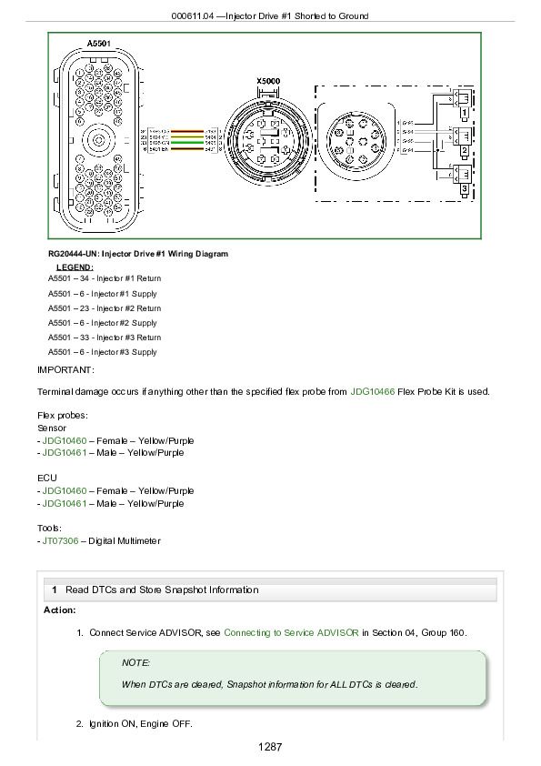
000611.04 - Injector Drive #1 Shorted to Ground
000612.03 - Injector Drive #2 Shorted to Voltage Source
000612.04 - Injector Drive #2 Shorted to Ground
000629.11 - ECU Binary Input Error
000629.12 - ECU EEPROM Error
000636.02 - Camshaft Position Signal Invalid
000636.05 - Camshaft Position Circuit Has High Resistance
000636.06 - Camshaft Position Circuit Has Low Resistance
000636.08 - Camshaft Position Signal Missing
000636.10 - Camshaft Position Signal Rate of Change Abnormal
000637.02 - Crankshaft Position Signal Invalid
000637.05 - Crankshaft Position Circuit Has High Resistance
000637.06 - Crankshaft Position Circuit Has Low Resistance
000637.07 - Crankshaft Position and Camshaft Position Signals Out of Sync
000637.08 - Crankshaft Position Signal Missing
000637.10 - Crankshaft Position Signal Rate of Change Abnormal
000640.11 - External Engine Protection Activated
000640.31 - External Derate Activated
000647.05 - Engine Fan Drive Circuit Has High Resistance
000647.06 - Engine Fan Drive Circuit Has Low Resistance
000647.07 - Engine Fan Speed Decrease Circuit Fault
000651.02 - Injector #1 Part Number Data Invalid
000651.05 - Injector #1 Circuit Has High Resistance
000651.06 - Injector #1 Circuit Has Low Resistance
000651.13 - Injector #1 Calibration Fault
000651.18 - Injector #1 Not Responding
000652.02 - Injector #2 Part Number Data Invalid
000652.05 - Injector #2 Circuit Has High Resistance
000652.06 - Injector #2 Circuit Has Low Resistance
000652.13 - Injector #2 Calibration Fault
000652.18 - Injector #2 Not Responding
000653.02 - Injector #3 Part Number Data Invalid
000653.05 - Injector #3 Circuit Has High Resistance
000653.06 - Injector #3 Circuit Has Low Resistance
000653.13 - Injector #3 Calibration Fault
000653.18 - Injector #3 Not Responding
000654.02 - Injector #4 Part Number Data Invalid
000654.05 - Injector #4 Circuit Has High Resistance
000654.06 - Injector #4 Circuit Has Low Resistance
000654.13 - Injector #4 Calibration Fault
000654.18 - Injector #4 Not Responding
000655.02 - Injector #5 Part Number Data Invalid
000655.05 - Injector #5 Circuit Has High Resistance
000655.06 - Injector #5 Circuit Has Low Resistance
000655.13 - Injector #5 Calibration Fault
000655.18 - Injector #5 Not Responding
000656.02 - Injector #6 Part Number Data Invalid
000656.05 - Injector #6 Circuit Has High Resistance
000656.06 - Injector #6 Circuit Has Low Resistance
000656.13 - Injector #6 Calibration Fault
000656.18 - Injector #6 Not Responding
000676.05 - Cold Start Aid Drive Circuit has High Resistance
000676.06 - Cold Start Aid Drive Circuit Has Low Resistance
000676.14 - Cold Start Aid Relay Signal Not Received When Expected
000676.31 - Cold Start Aid Signal Received When Not Expected
000695.19 - Unapproved Engine Speed Request
Group 163: DTC SPN - 000700—001999
000970.31 - External Shutdown Commanded
000971.31 - External Derate Commanded
000974.03 - Remote Analog Throttle Signal Out of Range High
000974.04 - Remote Analog Throttle Signal Out of Range Low
001075.02 - Low-Pressure Fuel Pump Data Erratic
001075.04 - Low-Pressure Fuel Pump Supply Voltage Low
001075.06 - Low-Pressure Fuel Pump Circuit Has Low Resistance
001075.09 - Low-Pressure Fuel Pump Loss of Communication
001075.15 - Low-Pressure Fuel Pump Temperature Slightly High
001110.31 - Engine Protection System Activated
001136.00 - ECU Temperature Signal Extremely High
001136.02 - ECU Temperature Signal Invalid
001136.16 - ECU Temperature Signal Moderately High
001321.05 - Engine Starter Solenoid Lockout Relay Circuit Has High Resistance
001321.06 - Engine Starter Solenoid Lockout Relay Circuit Has Low Resistance
001321.16 - Engine Starter Engaged for Too Long
001321.31 - Engine Speed Zero with Starter Solenoid Energized
001347.01 - Suction Control Valve Sticking and Fuel Rail Pressure Extremely Low
001347.05 - Suction Control Valve Circuit Has High Resistance
001347.06 - Suction Control Valve Circuit Has Low Resistance
001347.16 - Suction Control Valve Sticking and Fuel Rail Pressure Moderately High
001347.18 - Suction Control Valve Sticking and Fuel Rail Pressure Slightly Low
001550.05 - Air Conditioner Compressor Current Low
001550.06 - Air Conditioner Compressor Current High
001569.31 - Engine Power Derate Condition Exists
001638.03 - Hydraulic Oil Temperature Signal Out of Range High
001638.04 - Hydraulic Oil Temperature Signal Out of Range Low
001639.01 - Fan Speed Signal Extremely Low
001639.16 - Fan Speed Signal Moderately High
001639.18 - Fan Speed Signal Moderately Low
Group 164: DTC SPN - 002000—002299
002005.09 - No CAN Message Received From Source Address 5
002005.14 - Incorrect CAN Message Received From Source Address 5
002005.19 - Communication Error with Source Address 5
002006.09 - No CAN Message Received From Source Address 6
002006.14 - Incorrect CAN Message Received From Source Address 6
002006.19 - Communication Error with Source Address 6
002030.09 - No CAN Message Received From Source Address 30
002030.14 - Incorrect CAN Message Received From Source Address 30
002030.19 - Communication Error with Source Address 30
002040.09 - No CAN Message Received From Source Address 40
002040.14 - Incorrect CAN Message Received From Source Address 40
002040.19 - Communication Error with Source Address 40
002071.09 - No CAN Message Received From Source Address 71
002071.14 - Incorrect CAN Message Received From Source Address 71
002071.19 - Communication Error with Source Address 71
Group 165: DTC SPN - 002300—529999
002797.03 - Injector High Voltage Supply #1 Out of Range High
002797.05 - Injector High Voltage Supply #1 Circuit Has High Resistance
002797.06 - Injector High Voltage Supply #1 Circuit Has Low Resistance
002798.03 - Injector High Voltage Supply #2 Out of Range High
002798.05 - Injector High Voltage Supply #2 Circuit Has High Resistance
002798.06 - Injector High Voltage Supply #2 Circuit Has Low Resistance
003509.03 - Sensor Supply #1 Voltage Out of Range High
003509.04 - Sensor Supply #1 Voltage Out of Range Low
003510.03 - Sensor Supply #2 Voltage Out of Range High
003510.04 - Sensor Supply #2 Voltage Out of Range Low
003512.03 - Sensor Supply #4 Voltage Out of Range High
003512.04 - Sensor Supply #4 Voltage Out of Range Low
003513.03 - Sensor Supply #5 Voltage Out of Range High
003513.04 - Sensor Supply #5 Voltage Out of Range Low
003597.01 - Injector High Voltage Supply Extremely Low
005126.03 - Sensor Supply #8 Voltage Out of Range High
005126.04 - Sensor Supply #8 Voltage Out of Range Low
005127.03 - Sensor Supply #9 Voltage Out of Range High
005127.04 - Sensor Supply #9 Voltage Out of Range Low
055010.31 - Illegal ECU Structure
Section 05: Tools and Other Materials
Group 180: Special Tools
75240
205466
D01062AA
D01168AA
D01207AA
D01209AA
D01251AA
D01299AA
D01300AA
D05012ST-A
D05104ST
D05223ST
D17015BR
D17024BR
D17030BR
D17525CI
D17526CI
D17527CI
DFRG3
DFRG9
DFRG11
J-35616-20
JDE6
JDE38-2
JDE38-3
JDE93
JDE98A
JDE138
JDE41296
JDG23
JDG337
JDG360
JDG361
JDG362
JDG363
JDG364
JDG405
JDG451
JDG602
JDG606
JDG681A
JDG719
JDG721
JDG777
JDG782A
JDG783
JDG820
JDG839
JDG865
JDG1020
JDG1069
JDG1145
JDG1449
JDG1571
JDG1649A
JDG1948
JDG1949
JDG1962
JDG1963
JDG2046
JDG2047A
JDG2047AP1
JDG10015
JDG10025
JDG10040
JDG10057
JDG10059A
JDG10205
JDG10233
JDG10243
JDG10254
JDG10263
JDG10273
JDG10273P1
JDG10273P2
JDG10416
JDG10451
JDG10452
JDG10453
JDG10456
JDG10457
JDG10460
JDG10461
JDG10466
JDG10467
JDG10519
JDG10539A
JDG10545
JDG10549
JDG10631
JDG10760
JDG10942
JDG10993
JDG10994
JDG10997
JDG10998
JDG10999
JDG11016
JDG11017
JDG11019
JDG11055
JDG11056
JDG11072
JDG11100A
JDG11186
JDG11202
JDG11243
JDG11263
JDG11264
JDG11409
JDG11864
JDH7
JT01674A
JT03513C
JT05470
JT05697A
JT05719
JT07042
JT07253
JT07306
JT07336
Group 190: Lubricants, Sealants, and Other Materials
Other Materials
Section 06: Specifications
Group 210: Diagnostic Specifications
9.0 L Wiring Diagram 1
9.0 L Wiring Diagram 2
9.0 L Wiring Diagram 3
9.0 L Engine Schematic
Wire Splice Location Diagram
John Deere 6090 Diesel Engine (Level 24 ECU - Worldwide) Component Technical Manual (CTM115419)


