John Deere 6.8L & 8.1L PowerTech Diesel Engines Level 3 Electronic Fuel Systems with Bosch In-Line Pump Component Technical Manual (CTM134)
Catalog:
Model:
Complete Component Technical Manual for John Deere 6.8L & 8.1L PowerTech Diesel Engines Level 3 Electronic Fuel Systems with Bosch In-Line, with all the technical information to maintain, diagnose, repair, rebuild like professional mechanics.
John Deere 6.8L & 8.1L PowerTech Diesel Engines Level 3 Electronic Fuel Systems workshop service repair manual includes:
* Numbered table of contents easy to use so that you can find the information you need fast.
* Detailed sub-steps expand on repair procedure information
* Numbered instructions guide you through every repair procedure step by step.
* Troubleshooting and electrical service procedures are combined with detailed wiring diagrams for ease of use.
* Notes, cautions and warnings throughout each chapter pinpoint critical information.
* Bold figure number help you quickly match illustrations with instructions.
* Detailed illustrations, drawings and photos guide you through every procedure.
* Enlarged inset helps you identify and examine parts in detail.
ctm134 - John Deere 6.8L & 8.1L PowerTech Diesel Engines Level 3 Electronic Fuel Systems with Bosch In-Line Pump (Worldwide Edition) Component Technical Manual.pdf
ctm136 - Moteurs diesel PowerTech™ 6,8 l et 8,1 l Circuits d'alimentation électroniques niveau 3 avec pompe Bosch en ligne -: (Édition mondiale)
ctm135 - Motores diesel PowerTech™ de 6,8 l y 8,1 l con sistemas electrónicos de combustible del nivel 3 y bomba en línea Bosch -: (Edición mundial)
ctm137 - Elektronische Kraftstoffsysteme der Stufe 3 mit Reiheneinspritzpumpe von Bosch für PowerTech™ 6,8-l und 8,1-l-Dieselmotoren -: (Weltweite Ausgabe)
ctm138 - Motori diesel PowerTech™ da 6,8 e 8,1 l Impianti di alimentazione elettronici Livello 3 con pompa in linea Bosch -: (Edizione universale)
ctm140 - Дизельные двигатели PowerTech™ объемом 6,8 л и 8,1 л Электронные топливные системы уровня 3 с магистральным насосом Bosch -: (Исполнение для всех стран)
ctm184 - POWERTECH 8.1 6081.pdf
PRODUCT DETAILS:
Total Pages: 762 pages
File Format: PDF (bookmarked, ToC, Searchable, Printable, high quality)
Category: CTM
Language: English Spanish French German Italian Russian Chinese
Published on 2018/03/21
TABLE OF CONTENTS
Forward
Section 01: General
Group 000: Safety
Handle Fluids Safely—Avoid Fires
Handle Starting Fluid Safely
Service Cooling System Safely
Prevent Battery Explosions
Prepare for Emergencies
Handling Batteries Safely
Avoid High-Pressure Fluids
Wear Protective Clothing
Service Machines Safely
Work In Ventilated Area
Work in Clean Area
Remove Paint Before Welding or Heating
Avoid Heating Near Pressurized Fluid Lines
Illuminate Work Area Safely
Use Proper Lifting Equipment
Construct Dealer-Made Tools Safely
Practice Safe Maintenance
Use Proper Tools
Decommissioning — Proper Recycling and Disposal of Fluids and Components
Live With Safety
Group 001: Engine Identification
Engine Application Chart (John Deere Agricultural Equipment)
Engine Application Chart (John Deere Construction Equipment)
Engine Application Chart (OEM) (Outside Equipment Manufacturers)
Distinguishing ECUs on 8.1 L Engines
Distinguishing ECUs on 6.8 L Engines
Group 002: Fuels
Lubricants and Coolant
Diesel Fuel
Diesel Fuel Additive Products
Bio-Diesel Fuel
Lubricity of Diesel Fuel
Handle Fluids Safely—Avoid Fires
Handle Fluids Safely—Avoid Fires
Handle Starting Fluid Safely
Service Cooling System Safely
Prevent Battery Explosions
Prepare for Emergencies
Handling Batteries Safely
Avoid High-Pressure Fluids
Wear Protective Clothing
Service Machines Safely
Work In Ventilated Area
Work in Clean Area
Remove Paint Before Welding or Heating
Avoid Heating Near Pressurized Fluid Lines
Illuminate Work Area Safely
Use Proper Lifting Equipment
Construct Dealer-Made Tools Safely
Practice Safe Maintenance
Use Proper Tools
Decommissioning — Proper Recycling and Disposal of Fluids and Components
Live With Safety
Engine Application Chart (John Deere Agricultural Equipment)
Engine Application Chart (John Deere Agricultural Equipment)
Engine Application Chart (John Deere Construction Equipment)
Engine Application Chart (OEM) (Outside Equipment Manufacturers)
Distinguishing ECUs on 8.1 L Engines
Distinguishing ECUs on 6.8 L Engines
Lubricants and Coolant
Lubricants and Coolant
Diesel Fuel
Diesel Fuel Additive Products
Bio-Diesel Fuel
Lubricity of Diesel Fuel
Section 02: Repair and Adjustments
Group 090: Electronic Fuel System Repair and Adjustments
Fuel System — General Information
Relieve Fuel System Pressure
Replace Rectangular Fuel Filter Element
Replace Fuel Filter Check Valve
Replace Primary (Round) Fuel Filter/Water Separator
Identification of Fuel Supply Pumps
Remove Fuel Supply Pump
Inspect Fuel Supply Pump
Install Fuel Supply Pump
Service Injection Pump Overflow Valve
Identification of In-Line Fuel Injection Pumps
Service of Fuel Injection Pumps
Remove Fuel Injection Pump
Install Fuel Injection Pump
Remove Fuel Injection Nozzles
Test Fuel Injection Nozzles
Perform Opening Pressure Test
Injection Nozzle Opening Pressure Specifications
Perform Nozzle Leakage Test
Perform Chatter and Spray Pattern Test
Disassemble Fuel Injection Nozzle
Clean and Inspect Fuel Injection Nozzle Assembly
Clean Spray Orifices
Inspect Nozzle Holder
Inspect Gland Nut
Assemble Fuel Injection Nozzle
Inspect and Clean Cylinder Head Nozzle Bore
Inspect and Clean Nozzle Seating Surface
Install Fuel Injection Nozzles
Group 110: Electrical Engine Control Repair and Adjustment
John Deere Level 3 Electronic Engine Control System and Sensors
Remove and Install Sensors
Engine Control Unit (ECU)
Transient Voltage Protection (TVP) Module
Connectors
Diagnostic Connector Installation
Using High-Pressure Washer
Repair WEATHERPACK WEATHERPACK is a trademark of Packard Electric Connector
Install WEATHER PACK WEATHER PACK is a trademark of Packard Electric. Contact
Remove Blade Terminals from Connector Body
Repair (Pull Type) METRI-PACK METRI-PACK is a trademark of Delphi Packard Electric Systems Connectors
Repair (Push Type) METRI-PACK™ Connectors
Use Electrical Insulating Compound
Repair DEUTSCH Connectors
Install DEUTSCH DEUTSCH is a trademark of Deutsch Co. Contact
Fuel System — General Information
Fuel System — General Information
Relieve Fuel System Pressure
Replace Rectangular Fuel Filter Element
Replace Fuel Filter Check Valve
Replace Primary (Round) Fuel Filter/Water Separator
Identification of Fuel Supply Pumps
Remove Fuel Supply Pump
Inspect Fuel Supply Pump
Install Fuel Supply Pump
Service Injection Pump Overflow Valve
Identification of In-Line Fuel Injection Pumps
Service of Fuel Injection Pumps
Remove Fuel Injection Pump
Install Fuel Injection Pump
Remove Fuel Injection Nozzles
Test Fuel Injection Nozzles
Perform Opening Pressure Test
Injection Nozzle Opening Pressure Specifications
Perform Nozzle Leakage Test
Perform Chatter and Spray Pattern Test
Disassemble Fuel Injection Nozzle
Clean and Inspect Fuel Injection Nozzle Assembly
Clean Spray Orifices
Inspect Nozzle Holder
Inspect Gland Nut
Assemble Fuel Injection Nozzle
Inspect and Clean Cylinder Head Nozzle Bore
Inspect and Clean Nozzle Seating Surface
Install Fuel Injection Nozzles
John Deere Level 3 Electronic Engine Control System and Sensors
John Deere Level 3 Electronic Engine Control System and Sensors
Remove and Install Sensors
Engine Control Unit (ECU)
Transient Voltage Protection (TVP) Module
Connectors
Diagnostic Connector Installation
CAN Terminator Verification
Installation of Diagnostic Connector with Termination Present
Installation of Diagnostic Connector with no Termination Present
Using High-Pressure Washer
Repair WEATHERPACK™ Connector
Install WEATHER PACK™ Contact
Remove Blade Terminals from Connector Body
Repair (Pull Type) METRI-PACK™ Connectors
Repair (Push Type) METRI-PACK™ Connectors
Use Electrical Insulating Compound
Repair DEUTSCH Connectors
Install DEUTSCH™ Contact
Section 03: Theory of Operation
Group 130: Electronic Fuel System Operation
Fuel System Overview
Fuel Supply Pump Operation
Fuel Supply Pump Operation - Continued
Rectangular Final Fuel Filter Operation
Round Primary Fuel Filter/Water Separator Operation
Fuel Injection Pump Operation
Fuel Injection Nozzle Operation
Group 140: Electronic Control System Operation
Electronic Control System Overview
Electronic Control System Terminology
Electronic Control System Operation
Monitoring Engine Parameters
Measuring Temperature
Water In Fuel Sensor
Measuring Throttle Position
Measuring Oil Pressure
Measuring Engine Speed
Measuring Rack Position
Actuator Solenoid
Fuel Shut-off Solenoid
Engine Control Unit (ECU)
Cruise Control Operation
Intake Air Heater Operation
Engine Protection
Different Derate Programs
Multiple Torque Curve Selection
Governor Droop Mode Selection
Engine Control Unit (ECU) Self-diagnosis Operation
Fuel System Overview
Fuel System Overview
Fuel Supply Pump Operation
Fuel Supply Pump Operation - Continued
Rectangular Final Fuel Filter Operation
Round Primary Fuel Filter/Water Separator Operation
Fuel Injection Pump Operation
Fuel Injection Nozzle Operation
Electronic Control System Overview
Electronic Control System Overview
Electronic Control System Terminology
Electronic Control System Operation
Engine Starting Mode
Engine Running Mode
Monitoring Engine Parameters
Measuring Temperature
ECT (Engine Coolant Temperature) Sensor
MAT (Manifold Air Temperature) Sensor
AAT (Ambient Air Temperature) Sensor
Fuel Temperature Sensor
Loss of Coolant Temperature Switch
Charge Air Temperature Switch
Water In Fuel Sensor
Measuring Throttle Position
Measuring Oil Pressure
Measuring Engine Speed
Engine Speed Sensor
Injection Pump Speed Sensor
Measuring Rack Position
Actuator Solenoid
Fuel Shut-off Solenoid
Engine Control Unit (ECU)
Analog/Digital Converters
Central Processing Unit (CPU)
Memory
Cruise Control Operation
Intake Air Heater Operation
Engine Protection
Shutdown Override
Different Derate Programs
Low Oil Pressure Protection
High Engine Coolant Temperature Protection
Loss of Coolant Protection
High Charge Air Temperature Protection (“H” Engines Only)
High Fuel Temperature Protection
Multiple Torque Curve Selection
Governor Droop Mode Selection
Engine Control Unit (ECU) Self-diagnosis Operation
2 or 3–Digit Codes
SPN/FMI Codes
Section 04: Diagnostics
Group 150: Observable Diagnostics and Tests
About This Group of the Manual
E1 - Engine Cranks/Won't Start
E2 - Engine Misfires/Runs Irregularly
E3 - Engine Does Not Develop Full Power
E4 - Engine Emits Excessive Exhaust Smoke
E5 - Engine Emits Excessive Black or Gray Exhaust Smoke
E6 - Engine Will Not Crank
E7 - Engine Idles Poorly
E8 - Abnormal Engine Noise
F1 - Fuel Supply System Check
F2 - Excessive Fuel Consumption
F3 - Fuel in Oil
F4 - Excessive Fuel Filter Replacement
ECU Does Not Communicate with Service ADVISOR
D1 - ECU Does Not Communicate with DST
D2 - ECU Does Not Communicate with Diagnostic Gauge
D2 - ECU Does Not Communicate with Diagnostic Gauge
D3 - Error Codes on Electronic Governor Tester (JT05829)
D3 - Error Codes on Electronic Governor Tester (JT05829)
Check Fuel Supply Quality
Measure Fuel Supply Pump Pressure
Check Fuel Supply Pump Operation
Bleed the Fuel System
Cylinder Misfire Test
Test for Fuel Drain Back
Test for Air in Fuel
Check for Restricted Fuel Return Line
Check and Adjust Injection Pump Static Timing
Load Profile Information Test — Instructions
Primary CAN Diagnostic Procedure
Terminal Test
Diagnostic Test Box — Using
Group 160: Trouble Code Diagnostics and Tests
About This Group the Manual
Electrical Concept
Electrical Circuit Malfunctions
Troubleshooting Circuit Malfunctions
Using a Digital Multimeter
Using the JT07349 Break-Out-Box (BOB)
Determining Torque Curve Selection Using the Break-Out-Box (BOB)
Determining Governor Droop Mode Selection Using the Break-Out-Box (BOB)
Measuring Full Throttle Voltage Values Using Diagnostic Voltage Connector
Measuring Rack Position Voltage Using the Diagnostic Voltage Connector
Engine Configuration Data Parameters on Diagnostic Gauge
Viewing Active DTCs on Diagnostic Gauge
Viewing Stored DTCs on Diagnostic Gauge
Clearing Stored DTCs on Diagnostic Gauge
Blinking DTCs Using the Diagnostic Code Reader Connector
Clearing Stored Codes Using the Diagnostic Code Reader Connector
Connecting to Diagnostic Scan Tool (DST)
Connecting to Service ADVISOR
Data Parameter Description
Engine Control Unit (ECU) — Donating this Engine’s ECU to be Used Elsewhere
Engine Control Unit (ECU) — Replacing Current ECU with Another ECU
Engine Control Unit (ECU) — Replacing Current ECU with Another ECU — Cannot Communicate with Current ECU
Engine Control Unit (ECU) — Reprogramming Current ECU
Engine Control Unit (ECU) — Reprogramming Instructions
Downloading Payload File For DST
Reprogramming Engine Control Unit (ECU) With DST
Diagnostic Trouble Codes (DTCs)
Listing of Diagnostic Trouble Codes (DTCs) on ECU
Diagnostic Procedure
Intermittent Fault Diagnostics
T1 - Multi-state Throttle Input High
T1 - Multi-state Throttle Input High
T2 - Multi-state Throttle Input Low
T2 - Multi-state Throttle Input Low
T3 - Analog Throttle (A) Input High
T3 - Analog Throttle (A) Input High
T4 - Analog Throttle (A) Input Low
T4 - Analog Throttle (A) Voltage Input Low
T5 - Analog Throttle (B) Input High
T5 - Analog Throttle (B) Input High
T6 - Analog Throttle (B) Input Low
T6 - Analog Throttle (B) Input Low
T7 - CAN Throttle Invalid
T7 - CAN Throttle Invalid
T8 - PWM Throttle Input High
T8 - PWM Throttle Input High
T9 - PWM Throttle Input Low
T9 - PWM Throttle Input Low
T10 - PWM Abnormal Pulse Width
T10 - PWM Abnormal Pulse Width
000028.03 - Throttle Voltage High
000028.04 - Throttle Voltage Low
000029.03 - Throttle Voltage High
000029.04 - Throttle Voltage Low
000051.02 - Throttle Invalid
000091.03 - Throttle Voltage High
000091.04 - Throttle Voltage Low
000091.08 - PWM Throttle Abnormal Pulse Width
000091.09 - Throttle Invalid
000097.00 — Water in Fuel Continuously Detected
000097.00 - Water in Fuel Continuously Detected
000097.16 — Water in Fuel Detected
000097.16 - Water in Fuel Detected
000097.31 — Water in Fuel Detected
000097.31 - Water in Fuel Detected
000100.01 — Engine Oil Pressure Extremely Low
000100.01 - Engine Oil Pressure Extremely Low
000100.03 — Engine Oil Pressure Input Voltage High
000100.03 - Engine Oil Pressure Input Voltage High
000100.04 — Engine Oil Pressure Input Voltage Low
000100.04 - Engine Oil Pressure Input Voltage Low
000100.18 — Engine Oil Pressure Moderately Low
000100.18 - Engine Oil Pressure Moderately Low
000105.00 - Derated Torque Curve Selected
000105.03 — Manifold Air Temperature Input Voltage High
000105.03 - Manifold Air Temperature Input Voltage High
000105.04 — Manifold Air Temperature Input Voltage Low
000105.04 - Manifold Air Temperature Input Voltage Low
000105.09 - Manifold Air Temperature Invalid
000105.16 — Manifold Air Temperature Moderately High
000105.16 - Manifold Air Temperature Moderately High
000107.00 — Air Filter Restriction High
000107.00 - Air Filter Restriction High
000110.00 — Engine Coolant Temperature Extremely High
000110.00 - Engine Coolant Temperature Extremely High
000110.03 — Engine Coolant Temperature Input Voltage High
000110.03 - Engine Coolant Temperature Input Voltage High
000110.04 — Engine Coolant Temperature Input Voltage Low
000110.04 - Engine Coolant Temperature Input Voltage Low
000110.09 - Engine Coolant Temperature Invalid
000110.16 — Engine Coolant Temperature Moderately High
000110.16 - Engine Coolant Temperature Moderately High
000111.01 — Engine Coolant Level Low
000111.01 - Engine Coolant Level Low
000158.02 - Intermittent Loss of ECU Power Supply
000160.02 — Wheel Speed Input Noise
000160.02 - Wheel Speed Input Noise
000171.03 — Ambient Air Temperature Input Voltage High
000171.03 - Ambient Air Temperature Input Voltage High
000171.04 — Ambient Air Temperature Input Voltage Low
000171.04 - Ambient Air Temperature Input Voltage Low
000174.00 — Fuel Temperature Moderately High
000174.00 - Fuel Temperature Moderately High
000174.03 — Fuel Temperature Input Voltage High
000174.03 - Fuel Temperature Input Voltage High
000174.04 — Fuel Temperature Input Voltage Low
000174.04 - Fuel Temperature Input Voltage Low
000174.16 — Fuel Temperature Moderately High
000174.16 - Fuel Temperature Moderately High
000177.02 - Transmission Oil Temperature Erratic
000177.09 - Transmission Oil Temperature Invalid
000189.00 - Engine Speed Derate
000190.00 - Engine Overspeed Extreme
000190.02 — Engine Speed Input Noise
000190.02 - Engine Speed Input Noise
000190.03 — Engine Speed Input Voltage High
000190.03 - Engine Speed Input Voltage High
000190.04 — Engine Speed Input Voltage Low
000190.04 - Engine Speed Input Voltage Low
000190.05 — Engine Speed Sensor Circuit Open
000190.05 - Engine Speed Sensor Circuit Open
000190.14 — Engine Speed/Pump Speed Out of Sync
000190.14 - Engine Speed/Pump Speed Out of Sync
000190.16 - Engine Overspeed Moderate
000191.02 — Pump Speed Input Noise
000191.02 - Pump Speed Input Noise
000191.14 — Engine Speed/Pump Speed Out of Sync
000191.14 - Engine Speed/Pump Speed Out of Sync
000191.16 - Engine Overspeed Extreme
000620.03 — Sensor Supply Voltage High
000620.03 - Sensor Supply Voltage High
000620.04 — Sensor Supply Voltage Low
000620.04 - Sensor Supply Voltage Low
000629.13 — ECU Error
000629.13 - ECU Error
000632.11 — Fuel Shut-Off Circuit Fault
000632.11 - Fuel Shut-off Circuit Fault
000638.02 — Rack Instability
000638.02 - Rack Instability
000638.07 — Rack Position Error
000638.07 - Rack Position Error
000639.00 — CAN Error
000639.00 - CAN Error
000639.02 — CAN Error
000639.02 - CAN Error
000639.13 — CAN Error
000639.13 - CAN Error
000640.11 — Engine Shutdown Signal Invalid
000640.11 - Engine Shutdown Signal Invalid
000640.31 - Auxiliary Engine Shutdown Switch Active
000723.02 — Engine Speed Input Noise
000723.02 - Engine Speed Input Noise
000733.02 — Rack Position Error with Engine Off
000733.02 - Rack Position Error with Engine Off
000733.03 — Rack Position Voltage High
000733.03 - Rack Position Voltage High
000733.04 — Rack Position Voltage Low
000733.04 - Rack Position Voltage Low
000833.00 — Rack Position Calibration Error
000833.00 - Rack Position Calibration Error
000833.01 — Rack Position Calibration Error
000833.01 - Rack Position Calibration Error
000833.02 — Rack Position Error with Engine Off
000833.02 - Rack Position Error with Engine Off
000833.03 — Rack Position Voltage High
000833.03 - Rack Position Voltage High
000833.04 — Rack Position Voltage Low
000833.04 - Rack Position Voltage Low
000833.07 — Rack Position Calibration Error
000833.07 - Rack Position Calibration Error
000833.15 — Rack Position Calibration Error
000833.15 - Rack Position Calibration Error
000833.17 — Rack Position Calibration Error
000833.17 - Rack Position Calibration Error
000834.02 — Rack Instability
000834.02 - Rack Instability
000834.03 — Rack Actuator Control Circuit Short to Power
000834.03 - Rack Actuator Control Circuit Short to Power
000834.05 — Rack Actuator Control Circuit Open
000834.05 - Rack Actuator Control Circuit Open
000834.06 — Rack Actuator Control Circuit Short to Ground
000834.06 - Rack Actuator Control Circuit Short To Ground
000834.07 — Rack Position Error
000834.07 - Rack Position Error
000898.09 - Vehicle Speed Invalid
000970.00 - Auxiliary Engine Shutdown Switch Active
000970.11 — Engine Shutdown Signal Invalid
000970.11 - Engine Shutdown Signal Invalid
000970.31 - Auxiliary Engine Shutdown Switch Active
001041.02 — Start Signal Missing
001041.02 - Start Signal Missing
001041.03 — Start Signal Always Active
001041.03 - Start Signal Always Active
001069.09 - Tire Size Invalid
001069.31 - Tire Size Error
001082.09 - Engine Coolant Load Increase Invalid
001109.14 - Engine Shutdown
001110.31 - Engine Shutdown
001568.02 - Torque Curve Selection Invalid
001568.09 - Torque Curve Selection Invalid
001569.31 - Fuel Derate
001639.01 — Fan Speed Input Missing
001639.01 - Fan Speed Input Missing
001639.02 — Fan Speed Input Noise
001639.02 - Fan Speed Input Noise
001639.16 — Fan Speed Higher Than Expected
001639.16 - Fan Speed Higher Than Expected
001639.18 — Fan Speed Lower Than Expected
001639.18 - Fan Speed Lower Than Expected
002000.09 - Vehicle ID Missing
002000.13 - Security Violation
About This Group of the Manual
About This Group of the Manual
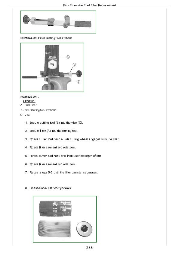
F4 - Excessive Fuel Filter Replacement
D2 - ECU Does Not Communicate with Diagnostic Gauge
D3 - Error Codes on Electronic Governor Tester (JT05829)
Check Fuel Supply Quality
Measure Fuel Supply Pump Pressure
Check Fuel Supply Pump Operation
Bleed the Fuel System
At Final Fuel Filter:
At Fuel Injection Pump:
At Fuel Injection Nozzles:
Cylinder Misfire Test
Test for Fuel Drain Back
Test for Air in Fuel
Check for Restricted Fuel Return Line
Check and Adjust Injection Pump Static Timing
Load Profile Information Test — Instructions
Updated View
Original view
Application List
Test Procedure
Saving the data
Diagnostic Test Box — Using
Diagnostic Test Box — Functionality
Before Connecting Diagnostic Test Box
Diagnostic Test Box — User Instructions
Diagnostic Test Box — Operational Test Procedure
About This Group the Manual
About This Group the Manual
Electrical Concept
Electrical Circuit Malfunctions
Circuit Malfunctions
Definition of Circuit Malfunctions
Locations of Circuit Malfunctions:
Troubleshooting Circuit Malfunctions
Using a Digital Multimeter
Using the JT07349 Break-Out-Box (BOB)
Determining Torque Curve Selection Using the Break-Out-Box (BOB)
Determining Governor Droop Mode Selection Using the Break-Out-Box (BOB)
Measuring Full Throttle Voltage Values Using Diagnostic Voltage Connector
Measuring Rack Position Voltage Using the Diagnostic Voltage Connector
Engine Configuration Data Parameters on Diagnostic Gauge
Viewing Active DTCs on Diagnostic Gauge
Viewing Stored DTCs on Diagnostic Gauge
Clearing Stored DTCs on Diagnostic Gauge
Blinking DTCs Using the Diagnostic Code Reader Connector
Clearing Stored Codes Using the Diagnostic Code Reader Connector
Connecting to Diagnostic Scan Tool (DST)
Connecting to Service ADVISOR
Connecting to Service ADVISOR with EDL Adapter using USB Cable
Connecting to Service ADVISOR with EDL Adaptor using Bluetooth
Data Parameter Description
Engine Control Unit (ECU) — Donating this Engine’s ECU to be Used Elsewhere
Additional Screens
Engine Control Unit (ECU) — Replacing Current ECU with Another ECU
Engine Control Unit (ECU) — Replacing Current ECU with Another ECU — Cannot Communicate with Current ECU
Engine Control Unit (ECU) — Reprogramming Current ECU
Engine Control Unit (ECU) — Reprogramming Instructions
Reprogramming Current ECU
Replacing Current ECU with Another ECU
Donating this Engines’ ECU to be Used Elsewhere
Replacing Current ECU with Another ECU — Cannot Communicate with Current ECU
Downloading Payload File For DST
Reprogramming Engine Control Unit (ECU) With DST
Diagnostic Trouble Codes (DTCs)
Listing of Diagnostic Trouble Codes (DTCs) on ECU
Ascending SPN/FMI Codes
2 or 3-Digit Codes
Diagnostic Procedure
Intermittent Fault Diagnostics
T1 - Multi-state Throttle Input High
T1 - Multi-state Throttle Input High
T2 - Multi-state Throttle Input Low
T2 - Multi-state Throttle Input Low
T3 - Analog Throttle (A) Input High
T3 - Analog Throttle (A) Input High
T4 - Analog Throttle (A) Input Low
T4 - Analog Throttle (A) Voltage Input Low
T5 - Analog Throttle (B) Input High
T5 - Analog Throttle (B) Input High
T6 - Analog Throttle (B) Input Low
T6 - Analog Throttle (B) Input Low
T7 - CAN Throttle Invalid
T7 - CAN Throttle Invalid
T8 - PWM Throttle Input High
T8 - PWM Throttle Input High
T9 - PWM Throttle Input Low
T9 - PWM Throttle Input Low
T10 - PWM Abnormal Pulse Width
T10 - PWM Abnormal Pulse Width
000097.00 — Water in Fuel Continuously Detected
000097.16 — Water in Fuel Detected
000097.31 — Water in Fuel Detected
000100.01 — Engine Oil Pressure Extremely Low
000100.03 — Engine Oil Pressure Input Voltage High
000100.04 — Engine Oil Pressure Input Voltage Low
000100.18 — Engine Oil Pressure Moderately Low
000105.03 — Manifold Air Temperature Input Voltage High
000105.04 — Manifold Air Temperature Input Voltage Low
000105.16 — Manifold Air Temperature Moderately High
000107.00 — Air Filter Restriction High
000110.00 — Engine Coolant Temperature Extremely High
000110.03 — Engine Coolant Temperature Input Voltage High
000110.04 — Engine Coolant Temperature Input Voltage Low
000110.16 — Engine Coolant Temperature Moderately High
000111.01 — Engine Coolant Level Low
000160.02 — Wheel Speed Input Noise
000171.03 — Ambient Air Temperature Input Voltage High
000171.04 — Ambient Air Temperature Input Voltage Low
000174.00 — Fuel Temperature Moderately High
000174.03 — Fuel Temperature Input Voltage High
000174.04 — Fuel Temperature Input Voltage Low
000174.16 — Fuel Temperature Moderately High
000190.02 — Engine Speed Input Noise
000190.03 — Engine Speed Input Voltage High
000190.04 — Engine Speed Input Voltage Low
000190.05 — Engine Speed Sensor Circuit Open
000190.14 — Engine Speed/Pump Speed Out of Sync
000191.02 — Pump Speed Input Noise
000191.14 — Engine Speed/Pump Speed Out of Sync
000620.03 — Sensor Supply Voltage High
000620.04 — Sensor Supply Voltage Low
000629.13 — ECU Error
000632.11 — Fuel Shut-Off Circuit Fault
000638.02 — Rack Instability
000638.07 — Rack Position Error
000639.00 — CAN Error
000639.02 — CAN Error
000639.13 — CAN Error
000640.11 — Engine Shutdown Signal Invalid
000723.02 — Engine Speed Input Noise
000733.02 — Rack Position Error with Engine Off
000733.03 — Rack Position Voltage High
000733.04 — Rack Position Voltage Low
000833.00 — Rack Position Calibration Error
000833.01 — Rack Position Calibration Error
000833.02 — Rack Position Error with Engine Off
000833.03 — Rack Position Voltage High
000833.04 — Rack Position Voltage Low
000833.07 — Rack Position Calibration Error
000833.15 — Rack Position Calibration Error
000833.17 — Rack Position Calibration Error
000834.02 — Rack Instability
000834.03 — Rack Actuator Control Circuit Short to Power
000834.05 — Rack Actuator Control Circuit Open
000834.06 — Rack Actuator Control Circuit Short to Ground
000834.07 — Rack Position Error
000970.11 — Engine Shutdown Signal Invalid
001041.02 — Start Signal Missing
001041.03 — Start Signal Always Active
001639.01 — Fan Speed Input Missing
001639.02 — Fan Speed Input Noise
001639.16 — Fan Speed Higher Than Expected
001639.18 — Fan Speed Lower Than Expected
Section 05: Tools and Other Materials
Group 170: Electronic Fuel/Control System Repair Tools and Other Materials
Fuel System Repair and Adjustment - Essential Tools
Fuel System Repair and Adjustment - Service Equipment and Tools
Fuel System Repair and Adjustment - Other Material
Control System Repair and Adjustment - Essential Tools
Control System Repair and Adjustment - Other Material
Group 180: Diagnostic Service Tools
JDE81-4
JDG820
JDG886
JDG10460
JDG10461
JDG10466
JDG11233
JDG11263
JT05470
JT05829
JT07306
JT07328
JT07349
Fuel System Repair and Adjustment - Essential Tools
Fuel System Repair and Adjustment - Essential Tools
Fuel System Repair and Adjustment - Service Equipment and Tools
Fuel System Repair and Adjustment - Other Material
Control System Repair and Adjustment - Essential Tools
Control System Repair and Adjustment - Other Material
JDE81-4
JDE81-4
JDG820
JDG886
JDG10460
JDG10461
JDG10466
JDG11233
JDG11263
JT05470
JT05829
JT07306
JT07328
JT07349
Section 06: Specifications
Group 200: Repair Specifications
Unified Inch Bolt and Screw Torque Values
Metric Bolt and Screw Torque Values
Electronic Fuel System Repair Specifications
Electronic Engine Control Repair Specifications
Group 210: Diagnostic Specifications
Fuel System Diagnostic Specifications
Torque Curve Selection
Governor Droop Mode Selection
Input Voltage to ECU for Applications with Analog Throttle at Full Throttle
6.8 L and 8.1 L OEM Application Electronic Control System Wiring Diagram
8.1L Marine Application Electronic Control System Wiring Diagram
6.8 L & 8.1 L OEM Application Instrument Panel/Engine Start Components Electrical Wiring Diagram
6.8 L & 8.1 L OEM Application Instrument Panel/Engine Start Components Electrical Wiring Diagram - Continued
Unified Inch Bolt and Screw Torque Values
Unified Inch Bolt and Screw Torque Values
Metric Bolt and Screw Torque Values
Electronic Fuel System Repair Specifications
Electronic Engine Control Repair Specifications
Fuel System Diagnostic Specifications
Fuel Injection Nozzle Delivery Lines
Overflow Valve on Injection Pump
Fuel Shut-off Solenoid
Fuel System Diagnostic Specifications
Fuel Injection Nozzle Delivery Lines
Overflow Valve on Injection Pump
Fuel Shut-off Solenoid
Torque Curve Selection
John Deere Applications
OEM and Marine Applications
Governor Droop Mode Selection
John Deere Applications
OEM and Marine Applications
Input Voltage to ECU for Applications with Analog Throttle at Full Throttle
6.8 L and 8.1 L OEM Application Electronic Control System Wiring Diagram
8.1L Marine Application Electronic Control System Wiring Diagram
6.8 L & 8.1 L OEM Application Instrument Panel/Engine Start Components Electrical Wiring Diagram
6.8 L & 8.1 L OEM Application Instrument Panel/Engine Start Components Electrical Wiring Diagram - Continued
ctm134 - 6.8L & 8.1L PowerTech™ Diesel Engines Level 3Electronic Fuel Systems with Bosch In-Line Pump -: (Worldwide Edition) Component Technical Manual Main Sections
Forward
Section 01: General
Safety
Engine Identification
Fuels
Section 02: Repair and Adjustments
Electronic Fuel System Repair and Adjustments
Electrical Engine Control Repair and Adjustment
Section 03: Theory of Operation
Electronic Fuel System Operation
Electronic Control System Operation
Section 04: Diagnostics
Observable Diagnostics and Tests
Trouble Code Diagnostics and Tests
Section 05: Tools and Other Materials
Electronic Fuel/Control System Repair Tools and Other Materials
Diagnostic Service Tools
Section 06: Specifications
Repair Specifications
Diagnostic Specifications
John Deere 6.8L & 8.1L PowerTech Diesel Engines Level 3 Electronic Fuel Systems with Bosch In-Line Pump Component Technical Manual (CTM134)


