John Deere Tractors 5103, 5203, 5303, 5403, 5045, 5055, 5065, 5075, 5204 Diagnostic and Repair Service Manual (TM900019)
Catalog:
Model:
Complete All Inclusive Technical Manual with electrical wiring diagrams for John Deere Tractors 5045D, 5045E, 5055D, 5055E, 5065E, 5075E, 5103, 5203, 5204, 5303, 5403 (PIN prefix PY), with workshop information to maintain, diagnostic, repair, service like professional mechanics (Diagnosis, Operation, Tests, Repair, Service, Troubleshooting).
John Deere Tractors 5103, 5203, 5303, 5403, 5045, 5055, 5065 & 5075 (USA, Mexico & Australia); 5103, 5203, 5303 & 5403 Australia Tractors; 5303 & 5403 Latin America Tractors; 5204 And 5303 Mexico Tractors workshop technical service manual includes:
* Numbered table of contents easy to use so that you can find the information you need fast.
* Detailed sub-steps expand on repair procedure information
* Numbered instructions guide you through every repair procedure step by step.
* Troubleshooting and electrical service procedures are combined with detailed wiring diagrams for ease of use.
* Notes, cautions and warnings throughout each chapter pinpoint critical information.
* Bold figure number help you quickly match illustrations with instructions.
* Detailed illustrations, drawings and photos guide you through every procedure.
* Enlarged inset helps you identify and examine parts in detail.
tm900019 English - John Deere 5103, 5203, 5303, 5403, 5045, 5055, 5065, 5075, 5204 (USA, Mexico, Australia, Argentina, Latin America) Technical Manual.pdf
tm900028 French - 5103, 5203, 5303, 5403, 5045, 5055, 5065, 5075, 5204 (USA, Mexique, Australie, Argentine, Amérique Latine)
tm900054 Portuguese - Tratores 5103, 5203, 5303 e 5403 Estados Unidos 5103, 5203, 5303 e 5403 Austrália 5303 e 5403 América Latina 5303 México
Total Pages: 2,251 pages
File Format: PDF (PC/Mac/Android/Kindle/iPhone/iPad; bookmarked, ToC, Searchable, Printable)
Category: Repair
Published on 2020/04/08
Covered models:
USA, Mexico, Australia Tractors:
5103
5203
5303
5403
5045D, 5045E
5055D, 5055E
5065E
5075E
Australia Tractors:
5103
5203
5303
5403
Latin America Tractors:
5303
5403
Mexico Tractors
5204
5303
MAIN SECTIONS
Foreword
General Information
Safety
General Specifications
Fuel and Lubricants
Serial Number Locations
Features and Accessories
Engine Repair
Engine
Cylinder Head and Valves
Cyl. Block, Liners, Pistons & Rods
Crankshaft, Main Bearings and Flywheel
Camshaft and Timing Gear Train
Lubrication System
Cooling System
Fuel and Air Repair
Fuel System
Air Intake and Exhaust System
Speed Control Linkage
Electrical Repair
Battery, Starter and Alternator
Electrical System Components
Wiring Harness
Power Train Repair
Clutch Housing
Clutch Assembly
'S' Transmission
'AA' Transmission
Rear PTO ('S' Transmission)
Rear PTO ('AA' Transmission)
Differential
Final Drives
Mechanical Front Wheel Drive
Steering and Brake Repair
Steering Repair
Brake Repair ('S' Transmission)
Brake Repair ('AA' Transmission)
Hydraulic Repair
Hydraulic Pump and Filter
MITA Rockshaft
JD Rockshaft
MITA Selective Control Valve (SCV)
EATON Selective Control Valve (SCV)
Mid Mount Selective Control Valve (SCV)
Miscellaneous Repair
Front Axle - 2WD
Wheels
3-Point Hitch
Hood
Operator Station Repair
Seat and Support
Center Console
Roll-Gard™
Operator Platform
Fenders
Canopy (If Equipped)
Operational Checkout Procedures
Operational Checkout Procedures
Engine Operation, Tests and Adjustments
Component Location
Theory of Operation
Diagnosis, Tests and Adjustments
Fuel/Air Operation, Test and Adjustments
Component Location
Theory of Operation
Diagnosis, Tests and Adjustments
Electrical System Operation, Tests & Adjust
Component Location
Theory of Operation-Latin America, Mexico, USA and Australia (5103, 5203, 5303, 5403) Tractors
Theory of Operation-USA and Australia Tractors
Diagnosis, Test and Adjust-Latin America, Mexico (5303), USA and Australia (5103, 5203, 5303, 5403) Tractors
Diagnosis, Test and Adjust-USA and Australia Tractors
Diagnosis, Test and Adjust (Mexico 5204 Tractors)
Wiring Schematics-Latin America, Mexico (5303), USA and Australia (5103, 5203, 5303, 5403) Tractors
Wiring Schematics-For USA and Australia Tractors
Wiring Schematics (Mexico 5204 Tractors)
Component Information-Connectors(For USA and Australia Tractors)
Power Train Operation, Tests and Adjustments
Component Location-Transmission
Theory of Operation-Transmission
Diagnosis, Tests, and Adjustments-Transmission
Steering and Brake Operation, Test & Adjustments
Component Location
Theory of Operation
Diagnosis, Tests and Adjustments
Hydraulic System Operation, Test and Adjustments
Component Location
Theory of Operation
Diagnosis
Hydraulic Tests - Without SCV
Hydraulic Tests-With SCV
Hydraulic Tests-With Mid Mount Control Valve
Hydraulic Tests - All
Adjustments
Hydraulic Schematics
TABLE OF CONTENTS
Section 10: General Information................39
Group 05: Safety................39
Recognize Safety Information................43
Understand Signal Words................44
Follow Safety Instructions................45
Handle Fluids Safely—Avoid Fires................46
Prevent Battery Explosions................47
Prepare for Emergencies................48
Prevent Acid Burns................49
Service Cooling System Safely................51
Avoid High-Pressure Fluids................52
Park Machine Safely................53
Support Machine Properly................54
Wear Protective Clothing................55
Work in Clean Area................56
Service Machines Safely................57
Work In Ventilated Area................58
Illuminate Work Area Safely................59
Replace Safety Signs................60
Use Proper Lifting Equipment................61
Service Tires Safely................62
Avoid Harmful Asbestos Dust................63
Avoid Heating Near Pressurized Fluid Lines................64
Remove Paint Before Welding or Heating................65
Use Proper Tools................66
Dispose of Waste Properly................67
Live With Safety................68
Group 10: General Specifications................1212
Machine Specifications (For USA and Australia Tractors)................72
Machine Specifications (For USA Tractors)................75
Machine Specifications (For Latin America Tractors)................81
Machine Specifications (Mexico Tractors)................83
Repair Specifications................1212
Ground Speed Estimates................89
Service Recommendations for O-Ring Boss Fittings................94
Service Recommendations for Flat Face O-Ring Seal Fittings................96
Metric Bolt and Cap Screw Torque Values................98
Unified Inch Bolt and Cap Screw Torque Values................99
Group 15: Fuel and Lubricants................40
Diesel Fuel................103
Biodiesel Fuel................105
Handling and Storing Diesel Fuel................107
Fuel Storage................108
Do Not Use Galvanized Containers................109
Fill Fuel Tank................110
Diesel Engine Oil — Non-Emissions Certified and Certified Tier 1 and Stage I................112
Diesel Engine Coolant (engine with wet sleeve cylinder liners)................114
Transmission and Hydraulic Oil................116
Grease (Specific Application)................117
Multipurpose Extreme Pressure (EP) Grease................118
Alternative and Synthetic Lubricants................119
Lubricant Storage................120
Group 20: Serial Number Locations................40
Serial Numbers................122
Product Identification Number Location................123
Engine Serial Number Location................124
Fuel Injection Pump Serial Number Location................125
Alternator Serial Number Location................126
Power Steering Valve Serial Number Location................127
Starter Serial Number Location................128
Transmission Serial Number Location................129
Front Axle Serial Number Location (2WD)................130
Front Axle Serial Number Location (MFWD)................131
Group 25: Features and Accessories................133
Features and Accessories................133
Standard Features................134
Factory Installed Optional Equipment................139
Field Installed Optional Kits and Accessories................140
Section 20: Engine Repair................141
Group 05: Engine................141
Service Equipment and Tools................861
Specifications................1212
John Deere Engine Repair—Use CTM................150
Remove Engine................151
Install Engine................158
Engine Disassembly Sequence................166
Sealant Application Guidelines................168
Engine Re-Assembly Sequence................169
Engine Break-In Guidelines................171
Perform Engine Break-In................172
Diesel Engine Break-In Oil................173
Group 10: Cylinder Head and Valves................141
Special or Essential Tools................1213
Specifications................1212
Torques for Hardware................386
Cylinder Head - Exploded View................234
Check Valve Lift................186
Remove Cylinder Head................187
Clean Injection Nozzle Bores................190
Valve Actuating Parts................191
Remove Valves and Valve Springs................192
Checking Cylinder Head Flatness................193
Clean Valve Guides................194
Measure Valve Guides................195
Knurl Valve Guides................197
Clean and Inspect Valve Seats................198
Lapping Valve Seats................199
Check Valve Recess................200
Remove Valve Seat Inserts................201
Valve Seat Insert Installation................203
Check Valves................204
Grind Valves................205
Check Valve Spring Compression................206
Inspect Valve Rotators................207
Install Valves................208
Install Cylinder Head................210
Torque Turn Tightening Method................212
Disassembling and Checking Rocker Arm Shaft................214
Reassembling Rocker Arm Shaft................216
Install Rocker Arm Assembly................217
Valve Clearance................218
Valve Adjustment Sequence................219
Install Rocker Arm Cover................220
Final Work................221
Group 15: Cyl. Block, Liners, Pistons & Rods................142
Special or Essential Tools................1213
Specifications................1212
Torques for Hardware................386
Exploded View................234
Connecting Rods - General Information................235
Remove Pistons and Connecting Rods................237
Measure Cylinder Liner Bore................239
Remove Cylinder Liners................240
Cylinder Liner Deglazing................241
Cylinder Block Cleaning................242
Check Piston Cooling Jets................243
Cam Follower Bore Measure................244
Measure Camshaft Bore................245
Remove Camshaft Bushing................246
Install Camshaft Bushing................247
Measure Crankshaft Bore................248
Replace Crankshaft Bearing Caps................249
Cylinder Block Top Desk Flatness................250
Measure Cylinder Liner Protrusion................251
Liner Packing Installation................253
Liner O-Ring Installation................254
Install Cylinder Liners................255
Measure Connecting Rod Bearing................256
Rod Bearing Clearance................258
Measure Connecting Rod Bushing................259
Replace Connecting Rod Bushing (3029D)................260
Replace Connecting Rod Bushing (3029T)................261
Measure Piston Pin................264
Clean and Inspect Pistons................265
Measure Piston Pin Bore................266
Piston Top Ring Groove................267
Second and Third Piston Ring Grooves................268
Piston Head and Skirt Checking................269
Install Piston Rings................270
Piston Rings Staggering................272
Piston/Liner Set Information................273
Assemble Piston and Connecting Rod................274
Install Piston and Connecting Rod................276
Measure Piston Protrusion................279
Complete Final Assembly................281
Group 20: Crankshaft, Main Bearings and Flywheel................143
Special or Essential Tools................1213
Specifications................1212
Torques For Hardware................289
Remove Crankshaft Pulley................290
Install Crankshaft Pulley................291
Flywheel Removal................292
Flywheel Ring Gear Replacement................293
Install Ball Bearing................294
Install Flywheel................295
Remove Crankshaft Rear Oil Seal................296
Flywheel Housing Replacement ('S' Transmission)................299
Flywheel Housing Replacement ('AA' Transmission)................301
Install Oil Seal/Wear Sleeve................303
Crankshaft End Play Measure................304
Remove Crankshaft................306
Crankshaft Inspection................307
Check Crankshaft Journal Diameter................308
Determine Crankshaft Main Bearing Clearance Using PLASTIGAGE PLASTIGAGE is a trademark of DANA Corp.................144
Regrind Crankshaft................311
Crankshaft Regrinding Guidelines................312
Micro-Finishing Specifications................1212
Replace Crankshaft Gear................314
Install Main Bearing Inserts................316
Install 2-Piece Thrust Bearing................317
Crankshaft Installation................318
Group 25: Camshaft and Timing Gear Train................144
Special or Essential Tools................1213
Specifications................1212
Torques for Hardware................386
Remove Crankshaft Front Oil Seal................327
Remove Timing Gear Cover................328
Measure Timing Gear Backlash................329
Camshaft End Play Measure................330
Remove Camshaft................331
Measure Camshaft Journal................332
Measure Height of Cam Lobe................333
Replace Camshaft Gear................334
Install Camshaft................335
Check Cam Follower................336
Idler Gear End Play Measure................337
Remove Front Plate................338
Idler Gear Bushing and Shaft Measure................340
Idler Gear Bushing Replacement................342
Remove Idler Shaft................343
Install Idler Shaft Spring Pin................344
Install Idler Shafts................345
Install Front Plate................346
Install Upper Timing Gear Train................348
Install Lower Timing Gear Train................350
Install Oil Deflector................351
Timing Gear Cover Identification................352
Install Timing Gear Cover................353
Install Crankshaft Front Oil Seal................355
Install Wear Ring................356
Install Auxiliary Equipment................357
Group 30: Lubrication System................145
Special or Essential Tools................1213
Specifications................1212
Torques for Hardware................386
Oil Cooler Identification................362
Remove Oil Cooler................363
Replace Oil Cooler Nipple................364
Install Oil Cooler................365
Replace Oil Cooler/Filter Bracket on Engine with Auxiliary Drive................366
Remove Oil Pressure Regulating Valve................368
Replace Oil Pressure Regulating Valve Seat................369
Install Oil Pressure Regulating Valve................370
Replace Oil Dipstick Guide................371
Replace Oil By-Pass Valve................372
Replace Oil Pump Strainer................373
Remove Oil Pump................374
Oil Pump Gear Axial Clearance................375
Oil Pump Gear Radial Clearance................376
Oil Pump Specifications................1212
Oil Pump Installation................378
Install Oil Pan................381
Group 35: Cooling System................146
Special or Essential Tools................1213
Specifications................1212
Torques for Hardware................386
Remove and Inspect Radiator................387
Remove and Inspect Radiator(5045D, 5045E, 5055D, 5055E, 5065E and 5075E Tractors)................146
Water Pump — Exploded View................396
Remove Water Pump................397
Disassemble Water Pump................398
Assemble Water Pump................400
Install Water Pump................403
Inspect Thermostat................404
Cooling System Deaeration................406
Check Fan/Alternator Belt Tension................407
Install Fan................409
Install Radiator................411
Install Radiator(5045D, 5045E, 5055D, 5055E, 5065E and 5075E Tractors)................146
Replace Thermostat................418
Section 30: Fuel and Air Repair................421
Group 05: Fuel System................421
Special or Essential Tools................1213
Injection Pump, Nozzle and Governor Repair—Use CTM................430
Remove, Inspect and Install Fuel Tank................431
Replace Fuel Filter................434
Replace Fuel Filter/Primer Pump Assembly................437
Remove Fuel Injection Pump................438
Repairs to Fuel Injection Pump................441
Replace Throttle Lever................442
Install Fuel Injection Pump................443
Remove Fuel Injection Nozzle................445
Clean Fuel Injection Nozzle................447
Fuel Injection Nozzle Disassembly................448
Install Fuel Injection Nozzle................449
Group 10: Air Intake and Exhaust System................421
Remove, Inspect, and Install Air Cleaner Elements................454
Check Air Inlet Pipe................456
Check Air Inlet Pipe with Turbocharger (If Equipped)................457
Exhaust Manifold Inspection (If Equipped)................458
Remove Turbocharger (If Equipped)................459
Turbocharger Cut-Away View (Borge Warner) - (If Equipped)................460
Check Radial Clearance................462
Check Axial Clearance................463
Repair Turbocharger (If Equipped)................464
Prelube Turbocharger (If Equipped)................465
Install Turbocharger (If Equipped)................466
Turbocharger Break-In (If Equipped)................469
Recommendations for Turbocharger Use (If Equipped)................470
Group 15: Speed Control Linkage................421
Inspect and Repair Speed Control Linkage................473
Section 40: Electrical Repair................475
Group 05: Battery, Starter and Alternator................475
Starter Repair—Use CTM77................477
Remove and Install Battery................478
Remove and Install Starter................480
Replace Alternator/Regulator................481
Group 10: Electrical System Components................475
Service Equipment and Tools................861
Other Material................1048
Replace Air Filter Restriction Sensor................486
Replace Coolant Temperature Sender................488
Replace Engine Speed Sensor................489
Replace Engine Oil Pressure Sensor................490
Replace Key Switch................491
Replace Light Switch................492
Replace Turn Signal Controller................494
Replace Instrument Panel................495
Replace Rear PTO Switch (If Equipped)................498
Remove and Install Rear PTO Switch-For 5045E, 5055E, 5065E and 5075E Tracators................499
Replace Park Position Start Switch................507
Replace Seat Switch (If Equipped)................508
Replace Fuel Level Sender................510
Group 15: Wiring Harness................475
Special or Essential Tools................1213
Service Parts Kits................899
Remove Connector Body from Blade Terminals................515
Replace WEATHER PACK WEATHER PACK is a trademark of Packard Electric. Connector................475
Install WEATHER PACK WEATHER PACK is a trademark of Packard Electric. Contact................475
Replace Tractor Wiring Harness................520
Replace Tractor Wiring Harness (5204 Mexico Tractor)................523
Section 50: Power Train Repair................526
Group 05: Clutch Housing................526
Service Equipment and Tools................861
Other Material................1048
Specifications................1212
Separate Engine from Clutch Housing................534
Install Engine to Clutch Housing................541
Replace Clutch Housing Seal ('S' Transmission)................548
Inspect and Repair Clutch Pedal and Linkage ('S' Transmission)................550
Inspect and Repair Clutch Pedal and Linkage ('AA' Transmission)................552
Group 10: Clutch Assembly................526
Essential Tools................1213
Service Equipment and Tools................861
Other Material................1048
Specifications................1212
Remove and Install Clutch Assembly................559
Disassemble and Inspect Clutch Assembly................562
Assemble Clutch Assembly................572
Traction Clutch Finger Adjustment................579
PTO Clutch Finger Adjustment................581
Remove and Inspect Clutch Release Mechanism and Shafts................583
Install Clutch Release Mechanism and Shafts................587
Group 15: 'S' Transmission................526
Specifications................1212
Separate Clutch Housing From Transmission................592
Install Clutch Housing to Transmission................596
Inspect and Repair Gear Shift Levers................600
Inspect and Repair Gear Shift Lever (For 5045E, 5055E, 5065E and 5075E Tractors)................602
Inspect and Repair Range Shift Lever................604
Inspect and Repair Range Shift Lever (For 5045E, 5055E, 5065E and 5075E Tractors)................606
Remove Transmission (‘S’ Transmission)................608
Disassemble and Inspect Transmission— Collarshift................613
Assemble Transmission — Collarshift................620
Disassemble and Inspect Transmission — SyncShuttle™................627
Assemble Transmission — SyncShuttle™................634
Install Transmission................692
Disassemble, Inspect and Assemble Gear Shift Shaft Assemblies................644
Disassemble, Inspect, and Assemble CollarShift Transmission Top Shaft................646
Disassemble, Inspect, and Assemble SyncShuttle™ Transmission Top Shaft— For Australia Tractors................649
Disassemble, Inspect, and Assemble SyncShuttle™ Transmission Top Shaft—For USA Tractors................652
Disassemble, Inspect, and Assemble Transmission Top Shaft—Partial SyncShuttle™ Transmission................655
Disassemble, Inspect, and Assemble Range Reduction Shaft................658
Disassemble, Inspect and Assemble Driven Shaft................700
Remove, Inspect, and Install Range Gears................662
Remove, Inspect, and Install Reverse Idler Shaft................664
Group 20: 'AA' Transmission................527
Other Material................1048
Specifications................1212
Remove, Inspect and Repair Gear Shift Lever And Cover................669
Remove, Inspect and Repair Gear Shift Lever And Cover (For 5045D and 5055D Tractors)................671
Remove, Inspect and Install Range and Reverse Shift Lever................673
Remove, Inspect and Install Range and Reverse Shift Lever (For 5045D and 5055D Tractors)................676
Remove Transmission................678
Disassemble and Inspect Transmission................680
Assemble Transmission................686
Install Transmission................692
Disassemble, Inspect and Assemble Shift Shaft Assemblies................694
Disassemble, Inspect, and Assemble Transmission Main Shaft................696
Disassemble, Inspect and Assemble Range Reduction Shaft................698
Disassemble, Inspect and Assemble Driven Shaft................700
Disassemble, Inspect and Assemble Traction Clutch Driven Shaft................702
Group 21: Rear PTO ('S' Transmission)................527
Other Material................1048
Specifications................1212
Remove, Inspect and Install Rear PTO Lever and Linkage................721
Remove, Inspect and Install Rear PTO Lever and Linkage - Cable Linkage................709
Remove, Inspect and Install Rear PTO Lever and Linkage - Cable Linkage - For 5045E, 5055E, 5065E and 5075E Tractors................711
Remove and Install Standard Rear PTO Drive Shaft Assembly................713
Disassemble, Inspect and Assemble Standard Rear PTO Drive Shaft Assembly................715
Group 25: Rear PTO ('AA' Transmission)................528
Other Material................1048
Specifications................1212
Remove, Inspect and Install Rear PTO Lever and Linkage................721
Remove, Inspect and Install Rear PTO Lever and Linkage - For 5045D and 5055D Tractors................724
Remove and Install Rear PTO Drive Shaft Assembly................728
Disassemble, Inspect and Assemble Rear PTO Drive Shaft Assembly................733
Disassemble, Inspect and Assemble Rear PTO Drive Shaft Assembly................733
Group 26: Differential................528
Essential Tools................1213
Service Equipment and Tools................861
Other Material................1048
Specifications................1212
Service Parts Kits................899
Remove and Install Differential Assembly................742
Disassemble, Inspect, and Assemble Differential Assembly ('S' Transmission)................744
Disassemble, Inspect and Assemble Differential Assembly ('AA' Transmission)................746
Remove and Inspect Differential Drive Shaft ('S' Transmission)................748
Install Differential Drive Shaft ('S' Transmission)................752
Remove and Inspect Differential Drive Shaft ('AA' Transmission)................756
Install Differential Drive Shaft ('AA' Transmission)................760
Remove, Inspect, and Install Differential Lock Assembly ('S' Transmission)................765
Remove, Inspect and Install Differential Lock Assembly ('AA' Transmission)................767
Differential Cone Point Adjustment................769
Differential Backlash Adjustment................771
Group 30: Final Drives................528
Service Equipment and Tools................861
Other Material................1048
Specifications................1212
Remove and Install Final Drive Assembly................777
Remove and Inspect Planetary Drive Assembly................780
Install Planetary Drive Assembly................783
Remove, Inspect, and Install Axle Shaft Assembly ('S' Transmission)................786
Remove, Inspect, and Install Axle Shaft Assembly ('AA' Transmission)................790
Group 35: Mechanical Front Wheel Drive................529
Essential Tools................1213
Other Material................1048
Specifications................1212
MFWD Axle Repair—Use CTM4870 and CTM4820................797
Inspect and Repair MFWD Lever and Linkage................798
Remove and Install MFWD Drop Gearbox................800
Disassemble and Inspect MFWD Drop Gearbox................802
MFWD Drop Gearbox Cross Section................805
Assemble MFWD Drop Gearbox................807
Remove, Inspect and Install MFWD Drive Shaft................813
Remove and Install MFWD Axle Housing Assembly................814
Remove, Inspect and Install Axle Supports (Without Paddy Seal)................816
Remove, Inspect and Install Axle Supports (With Paddy Seal)................818
Section 60: Steering and Brake Repair................820
Group 05: Steering Repair................820
Other Material................1048
Specifications................1212
Service Parts Kits................899
Remove and Install Steering Column and Valve................826
Remove and Install Steering Column and Valve - For 5045E, 5055E, 5065E and 5075E Tractors................828
Remove and Install Steering Column and Valve - For 5045D and 5055D Tractors................830
Disassemble and Inspect Steering Valve - Sauer Danfoss................832
Assemble Steering Valve - Sauer Danfoss................836
Disassemble and Inspect Steering Valve - Eaton................841
Assemble Steering Valve - Eaton................846
Remove and Install Steering Cylinder (Global Front Axle)................852
Disassemble, Inspect and Assemble Steering Cylinder (Global Front Axle)................853
Remove and Install Steering Cylinder (Fixed Front Axle)................854
Disassemble, Inspect and Assemble Steering Cylinder (Fixed Front Axle)................856
Remove, Inspect and Install Tie Rod Assembly................858
Group 10: Brake Repair ('S' Transmission)................820
Service Equipment and Tools................861
Other Material................1048
Specifications................1212
Remove and Install Brake Valve and Pedals................864
Disassemble and Inspect Brake Pedals and Valve................866
Brake Valve Cross Section................869
Assemble Brake Valve................871
Remove and Inspect Brakes (S- Transmission)................874
Install Brakes (S- Transmission)................877
Inspect and Replace Brake Hydraulic Lines................880
Group 15: Brake Repair ('AA' Transmission)................820
Other Material................1048
Specifications................1212
Remove and Install Brake Pedals and Linkage................885
Remove and Install Park Brake Lever and Linkage—For 5045D and 5055D Tractors (From Tractor Serial Number xxxxx)................887
Remove and Inspect Brakes................888
Install Brakes................890
Section 70: Hydraulic Repair................894
Group 05: Hydraulic Pump and Filter................894
Essential Tools................1213
Specifications................1212
Service Parts Kits................899
Remove, Inspect, and Install Hydraulic Oil Pick-Up Screen................900
Remove and Install Hydraulic Pump................902
Remove Hydraulic Pump External Components................904
Disassemble and Inspect Hydraulic Pump................905
Assemble Hydraulic Pump................908
Install Hydraulic Pump External Components................910
Remove and Install Hydraulic Oil Filter/Manifold................912
Inspect and Replace Hydraulic Supply and Suction/Return Lines................913
Group 10: MITA Rockshaft................894
Other Material................1048
Specifications................1212
Remove, Inspect, and Install Rockshaft Control Lever Assembly................918
Remove, Inspect, and Install Rockshaft Control Lever Support Assembly................921
Remove, Inspect and Install Rockshaft Control Linkage................928
Replace Main Relief Valve(MITA Rockshaft)................939
Remove, Inspect and Install Rate-of-Drop Valve................941
Replace Rockshaft Control Valve................944
Remove and Install Rockshaft Case(MITA Rockshaft)................948
Remove, Inspect and Install Rockshaft Lift Arms................950
Remove, Inspect and Install Rockshaft Piston and Cylinder................954
Group 15: JD Rockshaft................894
Other Material................1048
Specifications................1212
Inspect and Repair Rockshaft Control Lever Assembly................959
Inspect and Repair Rockshaft Control Linkage................964
Inspect and Repair Draft Sensing Support Assembly ('S' Rockshaft)................968
Inspect and Repair Draft Sensing Support Assembly ('AA' Rockshaft)................970
Replace Main Relief Valve(JD Rockshaft)................973
Replace Rockshaft Surge Relief Valve('S' Rockshaft)................895
Replace Rockshaft Surge Relief Valve('AA' Rockshaft)................895
Replace Rockshaft Control Valve(JD Rockshaft)................978
Remove and Install Rockshaft Case(JD Rockshaft)................982
Remove, Inspect, and Install Rockshaft Lift Arms ('S' Transmission)................985
Remove, Inspect, and Install Rockshaft Piston and Cylinder ('S' Transmission)................987
Remove, Inspect, and Install Rockshaft Lift Arms ('AA' Transmission)................990
Remove, Inspect, and Install Rockshaft Piston and Cylinder ('AA' Transmission)................992
Group 20: MITA Selective Control Valve (SCV)................895
Install Single Selective Control Valve (SCV)................1028
Install Rear Coupler Bracket................1031
Install Hydraulic Hoses................1042
Install Second Selective Control Valve (SCV)................1037
Assemble Rear Quick Coupler................1040
Install Hydraulic Hoses................1042
Group 25: EATON Selective Control Valve (SCV)................895
Install Single Selective Control Valve (SCV)................1028
Install Rear Coupler Bracket................1031
Install Hydraulic Hoses................1042
Install Second Selective Control Valve (SCV)................1037
Assemble Rear Quick Coupler................1040
Install Hydraulic Hoses................1042
Group 30: Mid Mount Selective Control Valve (SCV)................895
Service Parts Kit................1047
Other Material................1048
Specifications................1212
Remove and Install Mid Mount Control Valve................1050
Remove, Inspect and Install Joystick and Cables—Mid Mount Valve................1053
Disassemble, Inspect, and Assemble Joystick—Mid Mount Coupler................1055
Disassemble, Inspect and Assemble Mid Mount Control Valve................1057
Inspect and Replace Hydraulic Hoses—Mid Mount Coupler................1061
Section 80: Miscellaneous Repair................1063
Group 05: Front Axle - 2WD................1063
Specifications................1212
Remove and Install Front Axle................1066
Inspect and Replace Pivot Pin and Bushings................1070
Remove and Install Spindle Assembly................1072
Inspect and Replace Spindle Shaft Bushing (Adjustable Front Axle)................1074
Inspect and Replace Spindle Shaft Bushings (Fixed Front Axle)................1075
Group 10: Wheels................1063
Specifications................1212
Inspect and Replace Front Wheel Bearings................1078
Tighten Bolts—Rear Axle (M-20 Stud)................1080
Group 15: 3-Point Hitch................1063
Specifications................1212
Inspect and Repair Fixed Draft Links ('S' Transmission)................1083
Inspect and Repair Fixed Draft Links ('AA' Transmission)................1084
Inspect and Repair Telescoping Draft Links (If Equipped)................1086
Inspect and Repair Lift Link (If Equipped)................1090
Inspect and Repair Lift Link (If Equipped)................1090
Inspect and Repair Adjustable Lift Link (If Equipped)................1094
Inspect and Repair Adjustable Lift Link (If Equipped)................1094
Inspect and Repair Center Link................1096
Group 25: Hood................1063
Remove and Install Hood................1100
Section 90: Operator Station Repair................1102
Group 05: Seat and Support................1102
Remove and Install Seat and Support(For 5103, 5203, 5303 and 5403 Australia Tractors)................1102
Remove and Install Seat and Support(For 5103, 5203, 5303, 5403, 5045E, 5055E, 5065E and 5075E Tractors)................1102
Remove and Install Seat and Support(For 5045D and 5055D Tractors)................1102
Disassemble, Inspect and Assemble Seat and Seat Switch (For 5045D, 5045E, 5055D, 5055E, 5065E and 5075E ractors)................1111
Remove and Install Seat and Support(For 5303 and 5403 Latin America Tractors)................1102
Remove and Install Seat and Support(For 5204 and 5303 Mexico Tractor)................1102
Group 06: Center Console................1102
Remove Center Console Assembly................1120
Install Center Console Assembly................1123
Group 10: Roll-Gard™................1102
Specifications................1212
Remove and Install Roll-Gard................1128
ROPS Serial Number................1131
Group 15: Operator Platform................1102
Specifications................1212
Remove and Install Right-Side Platform and Step - Old................1134
Remove and Install Left-Side Platform and Step - Old................1136
Remove and Install Right-Side Platform and Step - New................1138
Remove and Install Left-Side Platform and Step - New................1140
Remove and Install Right-Side Platform and Step - 5045E, 5055E, 5065E and 5075E Tractors................1143
Remove and Install Left-Side Platform and Handrail - 5045E, 5055E, 5065E and 5075E Tractors................1145
Remove and Install Right-Side Platform and Step - 5045D and 5055D Tractors................1148
Remove and Install Left-Side Platform and Handrail - 5045D and 5055D Tractors................1151
Group 20: Fenders................1102
Remove and Install Fenders - Old................1155
Remove and Install Fenders................1156
Group 25: Canopy (If Equipped)................1102
Specifications................1212
Remove and Install Canopy................1160
Section 210: Operational Checkout Procedures................1162
Group 10: Operational Checkout Procedures................1162
Operational Checkout Procedure Information................1164
Engine Oil Level and Condition Check................1165
Coolant Level and Condition Check................1166
Transmission and Hydraulic Oil Check................1167
Fan and Belt Check................1169
Fuel System Check................1170
Air Intake System Check................1171
Electrical System Check................1172
Hydraulic System Check................1174
Indicator Lamps Check................1175
Engine Start Check................1176
Transmission Park Position Start Check................1177
Engine Fast and Slow Idle Operation................1179
Power Steering Check................1180
Differential Lock Check................1181
Clutch Check................1183
Transmission Shift Check................1185
Range Lever Shift Check................1186
Brake Check................1188
Rockshaft Check................1190
Selective Control Valve Check................1192
Miscellaneous Checks................1194
Section 220: Engine Operation, Tests and Adjustments................1195
Group 05: Component Location................1195
Component Location Information................2161
Engine External Components—Left-Hand Side................1199
Engine External Components—Right-Hand Side................1201
Group 10: Theory of Operation................1195
Theory of Operation Information................2165
Engine Lubrication System................1205
Engine Cooling System Operation................1209
Group 15: Diagnosis, Tests and Adjustments................1195
Specifications................1212
Essential Tools................1213
Diagnostic Information................2221
Engine Turns Over But Will Not Start or Starts Hard................1215
Engine Runs Irregularly or Stalls Frequently................1216
Engine Runs Rough................1217
Engine Has Low Power................1218
Engine Smokes—Black or Grey................1220
Engine Smokes Excessively—White................1221
Engine Uses Excess Fuel................1222
Engine Has Excess Noise or Vibration................1223
Engine Uses Excess Oil or Smokes Blue................1224
Engine Has Low Oil Pressure................1225
Engine Coolant Operating Temperature Incorrect................1226
Oil In Coolant or Coolant in Oil................1228
Radiator Bubble Test................1229
Cooling System Test................1232
Radiator Cap Pressure Test................1233
Engine Oil Pressure Test................1234
Cylinder Compression Pressure Test................1237
Fuel Shut-Off Solenoid Check (If Equipped)................1239
Throttle Lever Adjustment................1240
Slow Idle Adjustment (Rotary Pump)................1241
Fast Idle Adjustment (Rotary Pump)................1243
Idle Speed Adjustment (In-Line Pump)................1245
Injection Pump Timing Adjustment(Rotary Pump)................1196
Injection Pump Timing Adjustment(In-Line Pump)................1196
Valve Clearance Adjustment................1253
Fan/Alternator Drive Belt Adjustment................1255
Bleed Fuel System(For USA and Australia Tractors)................1196
Bleed Fuel System(For Latin America and Mexico Tractors)................1196
Bleed Fuel System At Fuel Injection Nozzles(For Latin America and Mexico Tractors)................1196
Section 230: Fuel/Air Operation, Test and Adjustments................1262
Group 05: Component Location................1262
Component Location Information................2161
Fuel System Components................1265
Fuel System Components- 5045E, 5055E, 5065E and 5075E Tractors................1268
Fuel System Components - 5045D and 5055D Tractors................1270
Air Intake System Components................1272
Group 10: Theory of Operation................1262
Theory of Operation Information................2165
Fuel System Operation ('S' Transmission)................1277
Fuel System Operation - For 5045E, 5055E, 5065E and 5075E Tractors................1279
Fuel System Operation ('AA' Transmission)................1281
Fuel System Operation - For 5045D and 5055D Tractors................1283
Fuel Filter Pump Operation................1285
Fuel Injection Pump Operation (Rotary Pump)................1287
Fuel Transfer (Feed) Pump Operation(In-Line Pump)................1262
Fuel Injection Pump Operation(In-Line Pump)................1262
In-Line Pump Governor Operation................1293
Fuel Injection Nozzle Operation................1295
Air Intake System Operation................1298
Turbocharger Operation................1301
Check Turbocharger Boost Pressure................1302
Diagnosing Turbocharger Malfunctions................1303
Group 15: Diagnosis, Tests and Adjustments................1262
Diagnostic Information................2221
Fuel/Air Diagnosis, Tests and Adjustments................1306
Section 240: Electrical System Operation, Tests Section 240: Electrical System Operation, Tests & Adjust{pgNO}1307 Adjust................1307
Group 05: Component Location................1307
Component Location Information................2161
Engine Electrical Components—Right Hand Side................1319
Engine Electrical Components—Left Hand Side................1320
Dash And Center Control Console Electrical Components—Latin America, Mexico, USA and Australia (5103, 5203, 5303, 5403) Tractors................1321
Dash And Center Control Console Electrical Components—(5103, 5203, 5303 and 5403) USA and Australia Tractors................1323
Dash And Center Control Console Electrical Components—5045E, 5055E, 5065E and 5075E Tractors................1325
Dash And Center Control Console Electrical Components—5045D and 5055D Tractors................1327
Tractor Electrical Components................1329
Tractor Electrical Components—5045E, 5055E, 5065E and 5075E Tractors................1331
Tractor Electrical Components—5045D and 5055D Tractors................1333
Group 10: Theory of Operation—Latin America, Mexico, USA and Australia (5103, 5203, 5303, 5403) Tractors................1307
Theory of Operation Information................2165
Fuse Block and Fuses................1337
Fuse Block and Fuses (Mexico 5204 Tractors)................1338
Relays................1382
Starting System Operation—Normal................1341
Starting System Operation—Bypass Attempt................1343
Charging System Operation................1345
Lighting System Operation—Left Turn Signals And Warn Lights................1347
Lighting System Operation—Right Turn Signals And Warn Lights................1350
Lighting System Operation—Warning Lights................1353
Lighting System Operation—Tail Lights................1356
Lighting System Operation—Headlights and Instrument Lights................1358
Instrument Panel System Operation—Tachometer/Hour Meter................1360
PTO Warning System Operation (If Equipped)................1362
Instrument Panel System Operation—Fuel Gauge................1364
Instrument Panel System Operation—Temperature Gauge................1366
Air Filter Restriction Indicator Operation................1368
7-Pin Trailer Outlet Connector Operation (If Equipped)................1370
Horn Operation - (Optional)................1372
Rear Work Light - (If Equipped)................1373
Group 15: Theory of Operation—USA and Australia Tractors................1308
Theory of Operation Information—For USA and Australia Tractors................1377
Fuse Block and Fuses—Type I................1379
Fuse Block and Fuses—Type II................1380
Relays................1382
Starting System Operation—Normal—Type I................1383
Starting System Operation—Normal—Type II................1385
Starting System Operation—Bypass Attempt—Type I................1388
Starting System Operation—Bypass Protection—Type II................1390
Starting System Operation—For 5045E, 5055E, 5065E, and 5075E Tractors (From Serial number XXXX)................1393
Charging System Operation—Type I................1395
Charging System Operation—Type II................1397
Lighting System Operation—Left Turn Signals And Warn Lights—Type I................1400
Lighting System Operation—Left Turn Signals And Warn Lights—Type II (with MARCUREX Flasher)................1308
Lighting System Operation—Right Turn Signals And Warn Lights—Type I................1407
Lighting System Operation—Right Turn Signals And Warn Lights—Type II (with MARCUREX Flasher)................1308
Lighting System Operation—Left Turn Signals And Warn Lights—Type II (with Hella Flasher)................1308
Lighting System Operation—Right Turn Signals And Warn Lights—Type II (with Hella Flasher)................1308
Lighting System Operation—Left Turn Signals And Warn Lights—Type II (with MARCUREX/Hella Flasher)................1308
Lighting System Operation—Right Turn Signals And Warn Lights—Type II (with MARCUREX/Hella Flasher)................1308
Lighting System Operation—Warning Lights—Type I................1428
Lighting System Operation—Warning Lights—Type II (with MARCUREX Flasher)................1308
Lighting System Operation—Warning Lights—Type II (with Hella Flasher)................1308
Lighting System Operation—Headlights and Instrument Lights—Type I................1435
Lighting System Operation—Headlights and Instrument Lights—Type II................1437
Lighting System Operation—Tail Lights—Type I................1439
Instrument Panel System Operation—Tachometer/Hour Meter—Type I................1441
Instrument Panel System Operation—Tachometer—Type II................1443
PTO Warning System Operation—Type I (Optional)................1445
PTO Warning System Operation—Type II................1447
Instrument Panel System Operation—Fuel Gauge—Type I................1449
Instrument Panel System Operation—Fuel Gauge—Type II................1451
Instrument Panel System Operation—Temperature Gauge—Type I................1453
Instrument Panel System Operation—Temperature Gauge—Type II................1455
Air Filter Restriction Indicator Operation—Type I................1457
Air Filter Restriction Indicator Operation—Type II................1459
7-Pin Trailer Outlet Connector Operation—Type I (Optional)................1461
7-Pin Trailer Outlet Connector Operation—Type II................1463
Horn Operation................1465
Rear Work Light—Type I (Optional)................1467
Rear Work Light—Type II (with Jumper Cable)................1469
Rear Work Light—Type II (without Jumper Cable)................1471
Group 20: Diagnosis, Test and Adjust—Latin America, Mexico (5303), USA and Australia (5103, 5203, 5303, 5403) Tractors................1309
Diagnostic Information................2221
Wire Color Chart................1583
Starting System Test Points—Normal Operation................1477
Starting System Test Points—Bypass Attempt................1484
Charging System Test Points................1755
Lighting System Test Points—Turn Signals And Enhanced Tail Lights................1494
Lighting System Test Points—Warning Lights................1499
Lighting System Test Points—Rear Flood Light................1768
Lighting System Test Points—Headlights and Instrument Lights................1772
Instrument Panel System Test Points—Tachometer/Hourmeter................1780
Instrument Panel System Test Points—Fuel Gauge................1782
Instrument Panel System Test Points—Temperature Gauge................1786
Instrument Panel System Test Points—Oil Pressure................1791
Air Filter Restriction Test Points................1796
Optional Horn Test Points................1801
Accessory Relay and Trailer Connector Test Points................1542
Battery Voltage and Specific Gravity Tests................1548
Charge Battery................1550
Battery Load Test................1552
Starter AMP Draw/RPM Test................1554
Starter No-Load AMP Draw/RPM Test................1556
Alternator/Regulator Test................1558
Starter Solenoid Test................1560
Starter Relay Test................1561
Key Switch Test................1563
Plug-In Relay Test................1565
Mini Plug-In Relay................1567
Diode Pack Test................1569
Fuse Test................1571
Park Position Start Switch Test................1572
PTO Switch Test................1573
PTO Seat Switch Test................1742
Light Switch Test................1743
Turn Signal Controller Test................1745
Fuel Shut-Off Solenoid Test................1746
Group 25: Diagnosis, Test and Adjust—USA and Australia Tractors................1310
Diagnostic Information................2221
Wire Color Chart................1583
Starting System Test Points—Normal Operation—Type I................1585
Starting System Test Points—Normal Operation—Type II................1592
Starting System Test Points—For 5045E, 5055E, 5065E, and 5075E Tractors (From Serial number XXXX)................1596
Starting System Test Points—Bypass Attempt—Type I................1600
Charging System Test Points—Type I................1606
Charging System Test Points—Type II................1611
Lighting System Test Points—Turn Signals And Enhanced Tail Lights—Type I................1614
Lighting System Test Points—Turn Signals And Enhanced Tail Lights—Type II (with Hella Flasher)................1310
Lighting System Test Points—Turn Signals And Enhanced Tail Lights—Type II (with MARCUREX Flasher)................1310
Lighting System Test Points—Warning Lights—Type I................1628
Lighting System Test Points—Warning Lights—Type II (with Hella Flasher)................1311
Lighting System Test Points—Warning Lights—Type II (with MARCUREX Flasher)................1311
Lighting System Test Points—Rear Flood Light—Type I................1638
Lighting System Test Points—Flood Lights—Type II (with Jumper Cable)................1311
Lighting System Test Points—Flood Lights—Type II (without Jumper Cable)................1311
Lighting System Test Points—Headlights and Instrument Lights—Type I................1646
Lighting System Test Points—Headlights and Instrument Lights—Type II................1656
Instrument Panel System Test Points—Manifold Heater—Type II................1660
Instrument Panel System Test Points—PTO Light—Type II................1662
Instrument Panel System Test Points—Tachometer/Hourmeter—Type I................1664
Instrument Panel System Test Points—Tachometer—Type II................1669
Instrument Panel System Test Points—Fuel Gauge—Type I................1671
Instrument Panel System Test Points—Fuel Gauge—Type II................1675
Instrument Panel System Test Points—Temperature Gauge—Type I................1678
Instrument Panel System Test Points—Temperature Gauge—Type II................1684
Instrument Panel System Test Points—Oil Pressure—Type I................1687
Instrument Panel System Test Points—Oil Pressure—Type II................1693
Air Filter Restriction Test Points—Type I................1695
Air Filter Restriction Test Points—Type II................1700
Horn Test Points—Type I (Optional)................1702
Horn Test Points—Type II................1706
Accessory Relay and Trailer Connector Test Points—Type I................1708
Accessory Relay and Trailer Connector Test Points—Type II................1714
Battery Voltage and Specific Gravity Tests (USA and Australia Tractors)................1716
Charge Battery (USA and Australia Tractors)................1718
Battery Load Test (USA and Australia Tractors)................1720
Starter AMP Draw/RPM Test (USA and Australia Tractors)................1722
Starter No-Load AMP Draw/RPM Test (USA and Australia Tractors)................1724
Alternator/Regulator Test (USA and Australia Tractors)................1726
Starter Solenoid Test (USA and Australia Tractors)................1728
Starter Relay Test (USA and Australia Tractors)................1729
Key Switch Test (USA and Australia Tractors)................1731
Plug-In Relay Test (USA and Australia Tractors)................1733
Mini Plug-In Relay (USA and Australia Tractors)................1735
Diode Pack Test (USA and Australia Tractors)................1737
Fuse Test (USA and Australia Tractors)................1739
Park Position Start Switch Test (USA and Australia Tractors)................1740
PTO Switch Test (USA and Australia Tractors)................1741
PTO Seat Switch Test................1742
Light Switch Test................1743
Turn Signal Controller Test................1745
Fuel Shut-Off Solenoid Test................1746
Group 30: Diagnosis, Test and Adjust (Mexico 5204 Tractors)................1312
Diagnostic Information................2221
Starting System Test Points—Normal Operation (Mexico 5204 Tractors)................1749
Charging System Test Points................1755
Lighting System Test Points—Turn Signals and Warning Lights................1760
Lighting System Test Points—Rear Flood Light................1768
Lighting System Test Points—Headlights and Instrument Lights................1772
Instrument Panel System Test Points—Tachometer/Hourmeter................1780
Instrument Panel System Test Points—Fuel Gauge................1782
Instrument Panel System Test Points—Temperature Gauge................1786
Instrument Panel System Test Points—Oil Pressure................1791
Air Filter Restriction Test Points................1796
Horn Test Points................1801
Battery Voltage and Specific Gravity Tests (Mexico 5204 Tractors)................1804
Charge Battery (Mexico 5204 Tractors)................1806
Battery Load Test (Mexico 5204 Tractors)................1808
Starter AMP Draw/RPM Test (Mexico 5204 Tractors)................1810
Starter No-Load AMP Draw/RPM Test (Mexico 5204 Tractors)................1812
Alternator/Regulator Test (Mexico 5204 Tractors)................1814
Starter Solenoid Test (Mexico 5204 Tractors)................1816
Starter Relay Test (Mexico 5204 Tractors)................1817
Plug-In Relay Test (Mexico 5204 Tractors)................1818
Diode Pack Test (Mexico 5204 Tractors)................1820
Fuse Test (Mexico 5204 Tractors)................1822
Neutral Start Switch Test................1823
Turn Signal Controller (Flasher) Test................1824
Group 35: Wiring Schematics—Latin America, Mexico (5303), USA and Australia (5103, 5203, 5303, 5403) Tractors................1313
Schematic Information................1892
Component Identification Table................1893
Electrical Schematic Legend................1835
Electrical Schematic Legend................1835
Electrical Schematic Legend................1835
Group 40: Wiring Schematics—For USA and Australia Tractors................1313
Schematic Information—For USA and Australia Tractors................1839
Component Identification Table................1893
Quick Reference Table—Type II................1842
SE1— Power Supply, SE2 — PTO, SE3 — Starting, SE4 — Charging, SE5 — Horn, SE6 — Lighting - Type I................1845
SE6 — Lighting, SE7 — Turn Signal and Warning Switch - Type I................1848
SE8 — Trailer Lighting outlet, SE9 — Instrumentation - Type I................1851
SE01 — Starting and Charging System - Type II................1854
SE01A - Starting Aid, Manifold Heater, and OTP Accessory Relay—Type II................1857
SE02 - Instrument, Gauges, Sensors, and Switches — Type II................1860
SE03 - Light Switch, Tail Turn Light, Relays/Flashers, and Turn Signal Switches — Type II................1863
SE03A - Light Switch, Tail Turn Light, Relays/Flashers, and Turn Signal Switches — Type II................1866
SE03B - Light Switch, Tail Turn Light, Relays/Flashers, and Turn Signal Switches — Type II................1869
SE04 - Trailer Connection 1 and Trailer Connection 2 — Type II................1872
SE05 - Flood Light, Right - Left Tail/Turn Light and Right - Left Head Light — Type II................1875
SE05A - Flood Light, Right - Left Tail/Turn Light and Right - Left Head Light — Type II................1878
SE06 - Horn, Reverse Alarm, Seat Switch and Horn Timer — Type II................1881
SE01 — Starting Motor, Charging Circuit, Jump Start and Back EMF Protection For 5045E, 5055E, 5065E, and 5075E Tractors (From Serial number XXXX)................1884
SE01A — Starting and Manifold Heater, OTP ACC Relay For 5045E, 5055E, 5065E, and 5075E Tractors (From Serial Number XXXX)................1885
SE02 — Instrument, Gauges, Sensors and Switches For 5045E, 5055E, 5065E, and 5075E Tractors (From Serial Number XXXX)................1887
SE03 — Light, Turn Switch, Tail Turn Light, Relays, Flasher and Flood Light For 5045E, 5055E, 5065E, and 5075E Tractors (From Serial Number XXXX)................1888
SE03A — Light, Turn Switch, Relays, Flasher and Flood Light For 5045E, 5055E, 5065E, and 5075E Tractors (From Serial Number XXXX)................1889
SE04 — Trailer Connector, SE05 — Horn, Reverse Alarm, Seat Switch and Horn Timer, SE06 — Brake Lights For 5045E, 5055E, 5065E, and 5075E Tractors (From Serial Number XXXX)................1890
Group 45: Wiring Schematics (Mexico 5204 Tractors)................1314
Schematic Information................1892
Component Identification Table................1893
Electrical Schematic................1895
Electrical Circuits................1897
Group 50: Component Information—Connectors(For USA and Australia Tractors)................1314
Component Location - Connectors (Summary of Information)................1900
X1 - 1-Pin Connector for Ground................1902
X2 - 16-Pin Connector for Instrument Panel................1903
X3 - 1-Pin Connector for Body Ground................1905
X4 and X5 - 6-Pin Connectors for Front to Rear Wiring Harness................1906
X6 and X7 - 6-Pin Connectors for Front to Rear Wiring Harness................1908
X8 - 1-Pin Connector for Ground................1910
X9 - 1-Pin Connector for Ground................1911
Section 250: Power Train Operation, Tests and Adjustments................1981
Group 05: Component Location—Transmission................1981
Component Location Information................2161
Power Train Components ('S' Transmission)................1986
Power Train Components - For 5045E, 5055E, 5065E and 5075E Tractors................1987
Power Train Components ('AA' Transmission)................1988
Power Train Components - For 5045D and 5055D Tractors................1989
Clutch Components—Dual................1990
CollarShift Transmission Components ('S' Transmission)................1992
SyncShuttle™ Transmission Components (For Australia Tractors)................1994
SyncShuttle™ Transmission Components (For USA Tractors)................1996
Partial SyncShuttle™ Transmission Components................1998
Collarshift Transmission Components ('AA' Transmission)................2000
Section 260: Steering and Brake Operation, Test Section 260: Steering and Brake Operation, Test & Adjustments{pgNO}2111 Adjustments................2111
Group 05: Component Location................2111
Component Location Information................2161
Steering System Components................2114
Hydraulic Brake System Components................2115
Mechanical Brake System Components................2117
Group 10: Theory of Operation................2111
Theory of Operation Information................2165
Steering System Operation................2121
Steering Valve Operation—Park Position and Manual Turning................2123
Steering Valve Operation—Power Turning................2125
Hydraulic Brake System Operation................2127
Brake Valve Operation................2129
Mechanical Brake System Operation................2133
Group 15: Diagnosis, Tests and Adjustments................2111
Diagnostic Information................2221
Isolate the Problem—Steering System................2137
Steering Sluggish or Loss of Steering................2138
Isolate the Problem—Brakes................2139
Excessive Brake Pedal Leak-Down................2140
Excessive Brake Chatter................2141
Steering Pump Flow Test................2234
Steering Valve Relief Test................2144
Steering Cylinder Leakage Test................2145
Steering Valve Leakage Test................2146
Checking Toe-In (Two Wheel Drive Tractor)................2148
Checking Toe - In (MFWD Tractor)................2149
Adjusting Toe-In (Two-Wheel Drive Tractor)................2150
Adjusting Toe-In (MFWD Tractor)................2151
Brake Pedal Adjustment ('S' Transmission)................2152
Bleed Brake System................2154
Brake Pedal Adjustment ('AA' Transmission)................2155
Section 270: Hydraulic System Operation, Test and Adjustments................2157
Group 05: Component Location................2157
Component Location Information................2161
Hydraulic System Components................2162
Group 10: Theory of Operation................2157
Theory of Operation Information................2165
Hydraulic System Operation................2166
Hydraulic Filter Operation................2169
Hydraulic Pump Operation................2171
MITA Selective Control Valve—Neutral Position................2173
MITA Selective Control Valve—Retract Position................2175
MITA Selective Control Valve—Extend Position................2177
MITA Selective Control Valve—Float Position................2179
EATON Selective Control Valve—Neutral Position................2181
EATON Selective Control Valve—Retract Position................2183
EATON Selective Control Valve—Extend Position................2185
EATON Selective Control Valve—Float Position................2187
MITA Rockshaft Control Valve Operation—Park Position................2189
MITA Rockshaft Control Valve Operation—Raise Position................2191
MITA Rockshaft Control Valve Operation—Lower Position................2193
MITA Rockshaft Draft - Sensing Operation................2195
MITA Surge (Safety) Relief Valve Operation................2197
MITA Rate-of-Drop Valve (Implement Lock) Operation................2199
JD Rockshaft Control Valve Operation—Neutral Phase................2201
JD Rockshaft Control Valve Operation—Delivery Phase................2203
JD Rockshaft Control Valve Operation—Discharge Phase................2205
JD Rockshaft Rate-of-Drop Valve (Implement Lock) Operation................2207
JD Rockshaft Draft-Sensing Operation................2209
JD Rockshaft Surge Relief Valve Operation................2211
JD Rockshaft Main Relief Valve Operation................2213
Functioning of Position Control................2215
Functioning of Draft Control................2217
Combined Functioning of Position and Draft Control................2219
Group 15: Diagnosis................2158
Diagnostic Information................2221
Preliminary Hydraulic System Inspection................2222
Entire Hydraulic System Fails to Function/No Hydraulic Pump Output................2223
Insufficient Pump Delivery................2224
Hydraulic Functions Too Slow................2225
Excessive Pump Pressure................2226
Slow Hydraulic Pump Response................2227
Excessive Pump Noise During Operation................2228
Rockshaft Does Not Lift or Lifts Slowly................2229
Rockshaft Does Not Lower or Lowers Slowly................2230
Park Position Unstable, Rockshaft Drops after Engine Shut Down................2231
Group 20: Hydraulic Tests - Without SCV................2158
Hydraulic System Tests................2233
Pump Flow Test................2234
MITA Rockshaft Main Relief Valve Test................2236
JD Rockshaft Main Relief Valve Test................2238
Group 25: Hydraulic Tests—With SCV................2158
Hydraulic System Tests—With SCV................2242
Pump Flow Test—With SCV................2244
Main Relief Valve Test—With SCV................2246
SCV Leakage Test................2248
Group 18: Hydraulic Tests—With Mid Mount Control Valve................2158
Hydraulic System Tests—With Mid Mount Control Valve................2251
Pump Flow Test—With Mid Mount Control Valve................2252
Main Relief Valve Test—With Mid Mount Control Valve................2254
Mid Mount Control Valve Leakage Test................2256
Group 30: Hydraulic Tests - All................2158
MITA Rockshaft Leakage Test................2259
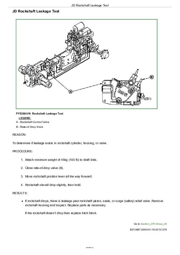
JD Rockshaft Leakage Test................2261
Rockshaft Lift Cycle Test................2262
Group 40: Adjustments................2158
Rockshaft Sensing Lever Friction Adjustment - MITA Rockshaft................2265
Control of Assembly of Reaction Spring- MITA Rockshaft................2266
Measurement Control of Push rod- MITA Rockshaft................2268
Adjustment of Position Control Lever- MITA Rockshaft................2269
Adjustment Of Draft Control Lever- MITA Rockshaft................2270
Rockshaft Lever Friction Adjustment- JD Rockshaft................2271
Rockshaft Position-Sensing Feedback Linkage Adjustment- JD Rockshaft................2272
Rockshaft Draft-Sensing Feedback Linkage Adjustment- JD Rockshaft................2276
Mid Mount Control Valve Joystick Cable Adjustment................2278
Group 45: Hydraulic Schematics................2159
Hydraulic Circuit Symbols................2282
Hydraulic System—Standard Tractor with First and Second Rear SCV................2284
John Deere Tractors 5103, 5203, 5303, 5403, 5045, 5055, 5065, 5075, 5204 Diagnostic and Repair Service Manual (TM900019)


