John Deere Tractors 5403, 5600, 5603, 5605, 5700, 5705 Diagnosis and Tests Service Technical Manual (TM8138)
Catalog:
Model:
Complete Diagnosis & Tests Technical Manual with electrical wiring diagrams for John Deere Tractors 5403, 5600, 5603, 5605, 5700, 5705, with all the shop information to maintain, diagnostic, service, rebuild like professional mechanics.
John Deere South America Tractors 5403, 5600, 5603, 5605, 5700, 5705 workshop Diagnosis & Tests technical manual includes:
* Numbered table of contents easy to use so that you can find the information you need fast.
* Detailed sub-steps expand on repair procedure information
* Numbered instructions guide you through every repair procedure step by step.
* Troubleshooting and electrical service procedures are combined with detailed wiring diagrams for ease of use.
* Notes, cautions and warnings throughout each chapter pinpoint critical information.
* Bold figure number help you quickly match illustrations with instructions.
* Detailed illustrations, drawings and photos guide you through every procedure.
* Enlarged inset helps you identify and examine parts in detail.
tm8138 English - John Deere 5403, 5600, 5603, 5605, 5700 and 5705 Tractors - Diagnosis and Tests Technical Manual.pdf
tm8140 French - Tracteurs 5403, 5600, 5603, 5605, 5700 et 5705 - Diagnostics.pdf
PRODUCT DETAILS:
Total Pages: 963 pages
File Format: PDF (bookmarked, ToC, Searchable, Printable, high quality)
Language: English
MAIN SECTIONS
Foreword
General Information
Safety
Engine System
Component Location
Theory of Operation
Operation, Tests and Adjustments
Electrical System (5600 and 5700)
How To Use Diagnostic Information
Electrical Components Test
Power Supply Overview
Engine Start Up
Engine Sensors
Engine Air Filter Sensor
PTO
Fuel Level
Horn
Lights
Connector Data
Electrical System (5403)
How To Use Diagnostic Information
Electrical Components Test
Power Supply Overview
Engine Start Up
Engine Sensors
Engine Air Filter Sensor
PTO
Fuel Level
Horn
Reverse Light and Backup Alarm
Lights
Connector Data
Electrical System (5603)
How To Use Diagnostic Information
Electrical Components Test
Power Supply Overview
Engine Start Up
Engine Sensors
Engine Air Filter Sensor
PTO
Fuel Level
Horn ( - 090000)
Horn (090001 - )
Reverse Light and Backup Alarm ( - 090000)
Reverse Light and Backup Alarm (090001 - )
Lights
Connector Data
Electrical System (5605 and 5705)
How To Use Diagnostic Information
Electrical Components Test
Power Supply Overview
Engine Start Up
Engine Sensors
Engine Air Filter Sensor
PTO
Fuel Level
Horn - 5605 ( - 090053) and 5705 ( - 0900125)
Horn - 5605 (090054 - ) and 5705 (0900126 - )
Reverse Light and Backup Alarm - 5605 ( - 090053) and 5705 ( - 090125)
Reverse Light and Backup Alarm - 5605 (090054 - ) and 5705 (090126 - )
Lights
Connector Data
Transmission Troubleshooting
Component Location - TSS Transmission
Theory of Operation - Carraro Clutch
Eaton Clutch and Transmission - Theory of Operation
Diagnostics, Tests and Adjustments - TSS Transmission
Brake and Steering
Location of Components
Theory of Operation - Brake and Steering
Steering and Brake - Diagnostics, Tests and Adjustments
Hydraulic System
Location of Components
Digital Temperature and Pressure Analyzer
Hydraulic System - Theory of Operation
Hydraulic System - Diagnostics
Hydraulic Test-Without SCV
Hydraulic Test-With SCV
Hydraulic Tests-General
Adjustments
Hydraulic Schematics
Others
TABLE OF CONTENTS
Section 10: General Information................23
Group 05: Safety................23
Recognize Safety Information................25
Understand Signal Words................26
Follow Safety Instructions................27
Handle Fluids Safely—Avoid Fires................28
Prevent Battery Explosions................29
Prepare for Emergencies................30
Prevent Acid Burns................31
Service Cooling System Safely................33
Handle Chemical Products Safely................34
Avoid High-Pressure Fluids................35
Park Machine Safely................36
Support Machine Adequately................37
Wear Protective Clothing................38
Work in Clean Area................39
Service Machines Safely................40
Work In Ventilated Area................41
Illuminate Work Area Safely................42
Replace Safety Signs................43
Use Proper Lifting Equipment................44
Keep ROPS Installed Properly................45
Service Tires Safely................46
Avoid Harmful Asbestos Dust................47
Avoid Heating Near Pressurized Fluid Lines................48
Remove Paint Before Welding or Heating................49
Use Proper Tools................50
Dispose of Waste Properly................51
Live With Safety................52
Section 220: Engine System................53
Group 05: Component Location................53
Information on Component Location................55
External Components of 4-Cylinder Engine—Left-Hand Side................56
External Components of 4-Cylinder Engine—Right-Hand Side................58
Group 10: Theory of Operation................599
Information on Theory of Operation................599
Operation of Engine Lubricating System................62
Operation of Engine Lubricating System—Continuation................64
Cooling System Operation—4-Cylinder Engine................66
Group 15: Operation, Tests and Adjustments................53
Check and Adjust Valve Clearance................71
Section 240: Electrical System (5600 and 5700)................74
Group 05: How To Use Diagnostic Information................729
Visual Inspection of Electrical System................514
Diagnostic Diagram and Information on Symbols in DiagramHow to use an Electrical Diagram................601
Electrical Diagram Symbols................518
Know the System................520
Ask the Operator................521
Group 10: Electrical Components Test................74
Battery Test................523
Recharging Battery................524
Important Recommendations about Batteries................525
Alternator Test................526
Battery Check................528
Test Starter Motor Solenoid................531
Starter Relay Test................534
Main Key Test................533
Relay Test................534
Diode Module Test................536
Fuse Test................537
PTO Sensor Test................538
Light Switch Test................539
Turn Signal Controller Test................540
Group 15A: Power Supply Overview................74
Theory of Operation................599
Diagram................543
Group 15B: Engine Start Up................74
Theory of Operation................599
Electrical Diagram................601
Diagnosing................603
Group 15C: Engine Sensors................74
Theory of Operation................599
Electrical Diagram................601
Diagnosing................603
Group 15D: Engine Air Filter Sensor................75
Theory of Operation................599
Electrical Diagram................601
Diagnosing................603
Group 15E: PTO................75
Theory of Operation................599
Electrical Diagram................601
Diagnosing................603
Group 15F: Fuel Level................75
Theory of Operation................599
Electrical Diagram................601
Diagnosing................603
Group 15G: Horn................75
Theory of Operation................599
Electrical Diagram................601
Diagnosing................603
Group 15H: Lights................75
Theory of Operation................599
Electrical Diagram................601
Diagnosing................603
Group 20: Connector Data................75
How to Use Connector Data................614
Wire Colors and Code Numbers................615
A01 - Fuse Box................616
A02 - Diode Module................618
A05 - Turn-Signal Switch................622
B01 - Neutral Start Switch................623
B02 - Air Filter Restriction Sensor Connector................624
B03 - Engine Oil Pressure Sensor................625
B04 - Engine Speed Sensor Connector................626
B05 - Coolant Temperature Sensor................627
B06 - Fuel Level Sensor................628
E01 - Left-Hand Headlight Connector................629
E02 - Right-Hand Headlight Connector................630
E04 - Front Right-Hand Clearance Light Connector................632
E05 - Front Left-Hand Clearance Light Connector................633
E06 - Rear Right-Hand Clearance Light Connector................634
E07 - Rear Left-Hand Clearance Light Connector................635
E08 - Front Right-Hand Turn Signal Light Connector................636
E09 - Front Left-Hand Turn Signal Connector................637
G02 - Alternator Connector................188
H03 - Horn Connector................639
KST - Starter Relay................642
K01 - Charge Relay 1................192
K02 - Charge Relay 2................193
K03 - Charge Relay 3................194
K04 - Brake Relay................195
K05 - Work Lights Relay................196
M01 - Starter Motor Terminals................641
S01 - Starter Switch................647
S02 - PTO Switch................649
S03 - Horn Switch................650
S05 - Right-Hand Brake Switch................652
S06 - Left-Hand Brake Switch................653
S09 - Lights Switch................654
X5 - Rear Clearance Light Grounding................655
X10 - Instrument Panel Connector................206
X11 - Connector between Front Wiring Harness and Rear Wiring Harness................347
X12 - Rear Right-Hand Position Light Connector................662
X13 - Rear Left-Hand Position Light................663
X26 - Starter Relay Ground................212
X29 - Ground Wire of Front Wiring Harness................669
X32 - Connector between Front Wiring Harness and Rear Wiring Harness................670
Y01 - Fuel Cut-Off Solenoid................672
Section 241: Electrical System (5403)................216
Group 05: How To Use Diagnostic Information................729
Visual Inspection of Electrical System................514
Diagnostic Diagram and Information on Symbols in DiagramHow to use an Electrical Diagram................601
Electrical Diagram Symbols................518
Know the System................520
Ask the Operator................521
Group 10: Electrical Components Test................216
Battery Test................523
Recharging Battery................524
Important Recommendations about Batteries................525
Alternator Test................526
Battery Check................528
Test Starter Motor Solenoid................531
Starter Relay Test................534
Main Key Test................533
Relay Test................534
Diode Module Test................536
Fuse Test................537
PTO Sensor Test................538
Light Switch Test................539
Turn Signal Controller Test................540
Group 15A: Power Supply Overview................216
Theory of Operation................599
Diagram................543
Group 15B: Engine Start Up................216
Theory of Operation................599
Electrical Diagram................601
Diagnosing................603
Group 15C: Engine Sensors................216
Theory of Operation................599
Electrical Diagram................601
Diagnosing................603
Group 15D: Engine Air Filter Sensor................217
Theory of Operation................599
Electrical Diagram................601
Diagnosing................603
Group 15E: PTO................217
Theory of Operation................599
Electrical Diagram................601
Diagnosing................603
Group 15F: Fuel Level................217
Theory of Operation................599
Electrical Diagram................601
Diagnosing................603
Group 15G: Horn................217
Theory of Operation................599
Electrical Diagram................601
Diagnosing................603
Group 15H: Reverse Light and Backup Alarm................217
Theory of Operation................599
Electrical Diagram................601
Diagnosing................603
Group 15I: Lights................217
Theory of Operation................599
Electrical Diagram................601
Diagnosing................603
Group 20: Connector Data................217
How to Use Connector Data................614
Wire Colors and Code Numbers................615
A01 - Fuse Box................616
A02 - Diode Module................618
A03 - Junction Box................620
A04 - Reverse Light and Backup Alarm................621
A05 - Turn-Signal Switch................622
B01 - Neutral Start Switch................623
B02 - Air Filter Restriction Sensor Connector................624
B03 - Engine Oil Pressure Sensor................625
B04 - Engine Speed Sensor Connector................626
B05 - Coolant Temperature Sensor................627
B06 - Fuel Level Sensor................628
E01 - Left-Hand Headlight Connector................629
E02 - Right-Hand Headlight Connector................630
E05 - Front Right-Hand Turn Signal Light Connector................476
E06 - Front Left-Hand Turn Signal Connector................477
E07 - Rear Clearance Light Connector................478
G02 - Denso Alternator Connector................328
G02 - Prestolite Alternator Connector................638
H03 - Horn Connector................639
KST - Starter Relay................642
K02 - Fuel Cut-Off Relay................644
K03 - Engine Jump Start Protection Relay................645
M01 - Starter Motor Terminals................641
S01 - Starter Switch................647
S02 - PTO Switch................649
S03 - Horn Switch................650
S04 - Reverse Travel Switch................651
S05 - Right-Hand Brake Switch................652
S06 - Left-Hand Brake Switch................653
S09 - Lights Switch................654
X5 - Rear Clearance Light Grounding................655
X10.1 - Instrument Panel Connector................656
X10.2 - Instrument Panel Connector................657
X11 - Connector between Front Wiring Harness and Rear Wiring Harness................347
X26 - Rear Wiring Harness Ground................666
X27 - Horn Grounding................667
X28 - Back-Up Alarm Grounding................668
X29 - Ground Wire of Front Wiring Harness................669
X32 - Connector between Front Wiring Harness and Rear Wiring Harness................670
X33 - Horn Wiring Harness Connector................671
Y01 - Fuel Cut-Off Solenoid................672
Section 242: Electrical System (5603)................356
Group 05: How To Use Diagnostic Information................729
Visual Inspection of Electrical System................514
Diagnostic Diagram and Information on Symbols in DiagramHow to use an Electrical Diagram................601
Electrical Diagram Symbols................518
Know the System................520
Ask the Operator................521
Group 10: Electrical Components Test................356
Battery Test................523
Recharging Battery................524
Important Recommendations about Batteries................525
Alternator Test................526
Battery Check................528
Test Starter Motor Solenoid................531
Starter Relay Test................534
Main Key Test................533
Relay Test................534
Diode Module Test................536
Fuse Test................537
PTO Sensor Test................538
Light Switch Test................539
Turn Signal Controller Test................540
Group 15A: Power Supply Overview................356
Theory of Operation................599
Diagram................543
Group 15B: Engine Start Up................356
Theory of Operation................599
Electrical Diagram................601
Diagnosing................603
Group 15C: Engine Sensors................356
Theory of Operation................599
Electrical Diagram................601
Diagnosing................603
Group 15D: Engine Air Filter Sensor................357
Theory of Operation................599
Electrical Diagram................601
Diagnosing................603
Group 15E: PTO................357
Theory of Operation................599
Electrical Diagram................601
Diagnosing................603
Group 15F: Fuel Level................357
Theory of Operation................599
Electrical Diagram................601
Diagnosing................603
Group 15G: Horn ( - 090000)................357
Theory of Operation................599
Electrical Diagram................601
Diagnosing................603
Group 15H: Horn (090001 - )................357
Theory of Operation................599
Electrical Diagram................601
Diagnosing................603
Group 15I: Reverse Light and Backup Alarm ( - 090000)................357
Theory of Operation................599
Electrical Diagram................601
Diagnosing................603
Group 15J: Reverse Light and Backup Alarm (090001 - )................357
Theory of Operation................599
Electrical Diagram................601
Diagnosing................603
Group 15K: Lights................357
Theory of Operation................599
Electrical Diagram................601
Diagnosing................603
Group 20: Connector Data................358
How to Use Connector Data................614
Wire Colors and Code Numbers................615
A01 - Fuse Box................616
A02 - Diode Module................618
A03 - Junction Box................620
A04 - Reverse Light and Backup Alarm................621
A05 - Turn-Signal Switch................622
B01 - Neutral Start Switch................623
B02 - Air Filter Restriction Sensor Connector................624
B03 - Engine Oil Pressure Sensor................625
B04 - Engine Speed Sensor Connector................626
B05 - Coolant Temperature Sensor................627
B06 - Fuel Level Sensor................628
E01 - Left-Hand Headlight Connector................629
E02 - Right-Hand Headlight Connector................630
E04 - Reverse Light Connector................475
E05 - Front Right-Hand Turn Signal Light Connector................476
E06 - Front Left-Hand Turn Signal Connector................477
E07 - Rear Clearance Light Connector................478
G02 - Prestolite Alternator Connector................638
H03 - Horn Connector................639
H04 - Back-up Alarm Connector................640
KST - Starter Relay................642
K02 - Fuel Cut-Off Relay................644
K03 - Engine Jump Start Protection Relay................645
M01 - Starter Motor Terminals................641
S01 - Starter Switch................647
S02 - PTO Switch................649
S03 - Horn Switch................650
S04 - Reverse Travel Switch................651
S05 - Right-Hand Brake Switch................652
S06 - Left-Hand Brake Switch................653
S09 - Lights Switch................654
X5 - Rear Clearance Light Grounding................655
X10.1 - Instrument Panel Connector................656
X10.2 - Instrument Panel Connector................657
X11 - Connector Between Front Wiring Harness and Rear Wiring Harness ( - 090000)................498
X11 - Connector between Front Wiring Harness and Rear Wiring Harness (090001 - )................500
X26 - Rear Wiring Harness Ground................666
X27 - Horn Grounding................667
X28 - Back-Up Alarm Grounding................668
X29 - Ground Wire of Front Wiring Harness................669
X32 - Connector between Front Wiring Harness and Rear Wiring Harness................670
X33 - Horn Wiring Harness Connector................671
Y01 - Fuel Cut-Off Solenoid................672
Section 243: Electrical System (5605 and 5705)................509
Group 05: How To Use Diagnostic Information................729
Visual Inspection of Electrical System................514
Diagnostic Diagram and Information on Symbols in DiagramHow to use an Electrical Diagram................601
Electrical Diagram Symbols................518
Know the System................520
Ask the Operator................521
Group 10: Electrical Components Test................509
Battery Test................523
Recharging Battery................524
Important Recommendations about Batteries................525
Alternator Test................526
Battery Check................528
Test Starter Motor Solenoid................531
Starter Relay Test................534
Main Key Test................533
Relay Test................534
Diode Module Test................536
Fuse Test................537
PTO Sensor Test................538
Light Switch Test................539
Turn Signal Controller Test................540
Group 15A: Power Supply Overview................509
Theory of Operation................599
Diagram................543
Group 15B: Engine Start Up................509
Theory of Operation................599
Electrical Diagram................601
Diagnosing................603
Group 15C: Engine Sensors................509
Theory of Operation................599
Electrical Diagram................601
Diagnosing................603
Group 15D: Engine Air Filter Sensor................510
Theory of Operation................599
Electrical Diagram................601
Diagnosing................603
Group 15E: PTO................510
Theory of Operation................599
Electrical Diagram................601
Diagnosing................603
Group 15F: Fuel Level................510
Theory of Operation................599
Electrical Diagram................601
Diagnosing................603
Group 15G: Horn — 5605 ( - 090053) and 5705 ( - 0900125)................510
Theory of Operation................599
Electrical Diagram................601
Diagnosing................603
Group 15H: Horn — 5605 (090054 - ) and 5705 (0900126 - )................510
Theory of Operation................599
Electrical Diagram................601
Diagnosing................603
Group 15I: Reverse Light and Backup Alarm — 5605 ( - 090053) and 5705 ( - 090125)................510
Theory of Operation................599
Electrical Diagram................601
Diagnosing................603
Group 15J: Reverse Light and Backup Alarm — 5605 (090054 - ) and 5705 (090126 - )................510
Theory of Operation................599
Electrical Diagram................601
Diagnosing................603
Group 15K: Lights................510
Theory of Operation................599
Electrical Diagram................601
Diagnosing................603
Group 20: Connector Data................511
How to Use Connector Data................614
Wire Colors and Code Numbers................615
A01 - Fuse Box................616
A02 - Diode Module................618
A03 - Junction Box................620
A04 - Reverse Light and Backup Alarm................621
A05 - Turn-Signal Switch................622
B01 - Neutral Start Switch................623
B02 - Air Filter Restriction Sensor Connector................624
B03 - Engine Oil Pressure Sensor................625
B04 - Engine Speed Sensor Connector................626
B05 - Coolant Temperature Sensor................627
B06 - Fuel Level Sensor................628
E01 - Left-Hand Headlight Connector................629
E02 - Right-Hand Headlight Connector................630
E03 - Reverse Light Connector................631
E04 - Front Right-Hand Clearance Light Connector................632
E05 - Front Left-Hand Clearance Light Connector................633
E06 - Rear Right-Hand Clearance Light Connector................634
E07 - Rear Left-Hand Clearance Light Connector................635
E08 - Front Right-Hand Turn Signal Light Connector................636
E09 - Front Left-Hand Turn Signal Connector................637
G02 - Prestolite Alternator Connector................638
H03 - Horn Connector................639
H04 - Back-up Alarm Connector................640
M01 - Starter Motor Terminals................641
KST - Starter Relay................642
K02 - Fuel Cut-Off Relay................644
K03 - Engine Jump Start Protection Relay................645
K04 - Work Lights Relay................646
S01 - Starter Switch................647
S02 - PTO Switch................649
S03 - Horn Switch................650
S04 - Reverse Travel Switch................651
S05 - Right-Hand Brake Switch................652
S06 - Left-Hand Brake Switch................653
S09 - Lights Switch................654
X5 - Rear Clearance Light Grounding................655
X10.1 - Instrument Panel Connector................656
X10.2 - Instrument Panel Connector................657
X11 - Connector between Front Wiring Harness and Rear Wiring Harness—5605 ( - 090053) and 5705 ( - 090125)................658
X11 - Connector between Front Wiring Harness and Rear Wiring Harness—5605 (090054 - ) and 5705 (090126 - )................660
X12 - Rear Right-Hand Position Light Connector................662
X13 - Rear Left-Hand Position Light................663
X14 - Rear Right-Hand Clearance Light Connector................664
X15 - Rear Left-Hand Clearance Light Connector................665
X26 - Rear Wiring Harness Ground................666
X27 - Horn Grounding................667
X28 - Back-Up Alarm Grounding................668
X29 - Ground Wire of Front Wiring Harness................669
X32 - Connector between Front Wiring Harness and Rear Wiring Harness................670
X33 - Horn Wiring Harness Connector................671
Y01 - Fuel Cut-Off Solenoid................672
Section 250: Transmission Troubleshooting................673
Group 05: Component Location — TSS Transmission................673
Information Regarding the Location of Components................677
Drive Train Components................678
Clutch Components................679
Transmission Components—TSS................681
Final Drive Components................683
Rear PTO Components................684
Group 10 A: Theory of Operation — Carraro Clutch................673
Clutch Operation — Carraro................687
Clutch Operation — Continuation................691
Clutch Operation — Continuation................691
Group 10 B: Eaton Clutch and Transmission — Theory of Operation................599
Information on the Theory of Operation................694
Clutch Operation—CollarShift and SyncShuttle™ Transmissions................695
Transmission Lubrication System................703
CollarShift Transmission—Gear Shift Power Flow................705
SyncShuttle™ Transmission—Gear Shift Power Flow................707
SyncShuttle™ Transmission Synchronizer Operation—Reverse and 2nd Gear (Disk-and-Plate Type Synchronizer)................709
SyncShuttle™ Transmission Synchronizer Operation—1st and 3rd Gear (Cone-Type Synchronizer)................711
CollarShift Transmission—Shift Range Power Flow................713
PTO Power Flow................716
Rear PTO Operation................717
Differential Power Flow................719
Differential Power Flow................719
Differential Lock Operation................721
Differential Lock Operation................721
Final Drive Operation................722
Mechanical Front Wheel Drive (MFWD) Drop Gearbox Operation................726
Mechanical Front Wheel Drive (MFWD) Drop Gearbox Operation................726
Group 15: Diagnostics, Tests and Adjustments — TSS Transmission................673
Diagnostic Information................729
Isolate the Problem Area................731
Isolate the Problem Area — Continued................732
The Drive Clutch Slides................733
Drive Clutch Drag................734
Drive Clutch Does Not Engage................735
The Drive Clutch Sticks................736
Drive Clutch Creaking................737
Drive Clutch Does Not Release................738
Drive Clutch Vibrates................739
The Drive Clutch Creaks................740
The Drive Clutch Actuation Is Noisy................741
Excessive Vibration on the Drive Clutch................742
Clutch Pedal Does Not Return................743
Loose Clutch Pedal................744
Clutch Pedal Throbs................745
Power Transmission Abrupt or Leaping................746
Transmission Oil Level Low (Excessive Oil Leaking)................747
Gears Are Bumby, Are Hard to Engage or Do Not Engage................748
Two Gears Engage Together................749
Transmission Does Not Stay in Gear................750
Noisy Transmission................751
Noisy PTO................752
Hard to Engage PTO................753
PTO Does Not Operate................754
PTO does not Stay Activated................755
Excessive Differential Noise................756
Differential Does Not Operate................757
No Differential Lock................758
Differential Vibrates................759
Noisy Axle................760
Axle Does Not Turn................761
Difficulty in Engaging PTO Lever................762
MFWD Lever Does Not Stay in "ON" Position................763
Noisy MFWD Operation................764
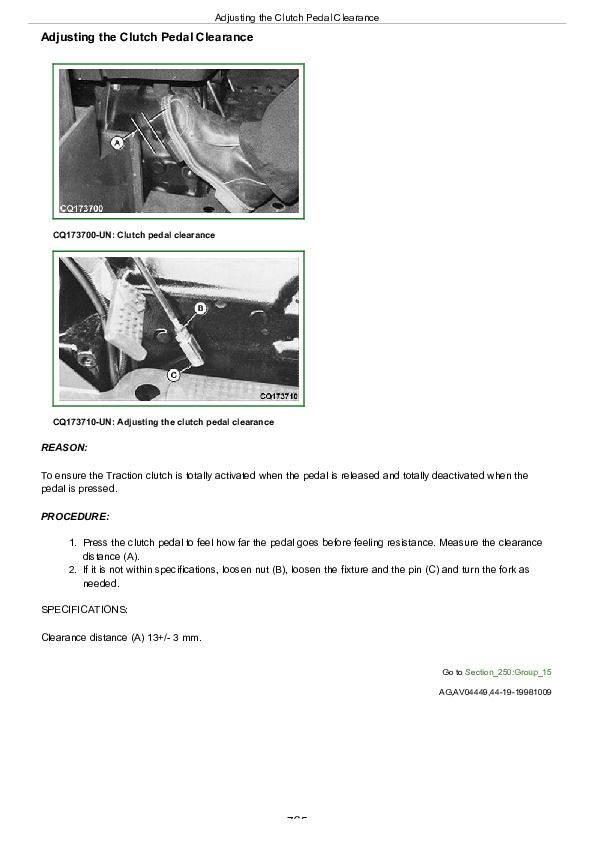
Adjusting the Clutch Pedal Clearance................765
Adjusting the PTO Clutch Lever................766
Section 260: Brake and Steering................768
Group 05: Location of Components................768
Information about the Location of the Components................814
Steering System Components................771
Brake System Components................772
Group 10: Theory of Operation — Brake and Steering................768
Information About the Operation Theory................831
Steering System Operation................776
Steering Valve Operation — Manual Turn and Neutral................778
Steering Valve Operation — Power Assisted Turning................780
Brake System Operation................782
Brake Valve Operation................784
Brake Valve Operation — Continued................786
Brake Valve Operation — Resting Brake Pedal................787
Group 15: Steering and Brake — Diagnostics, Tests and Adjustments................768
Diagnostic Information for the Electrical System................790
Isolate the Problem — Steering System................792
Slow Steering or Loss of Steering................793
Isolate the Problem — Brakes................794
Excessive Brake Pedal Leak................795
Excessive Brake Vibration................796
Steering Pump Flow Test................797
Steering Valve Relief Test................798
Steering Cylinder Leakage Test................799
Steering Valve Leakage Test................800
Checking the Toe-In — Two-Wheel Drive................802
Adjusting the Toe-In — Two-Wheel Drive................803
Checking the Toe-In — Four-Wheel Drive................804
Adjusting the Toe-In — Four-Wheel Drive................805
Adjusting the Turning Angle of the Steering Backstop — Four-Wheel Drive................806
Brake Pedal Adjustment................807
Bleed Brake System................809
Section 270: Hydraulic System................810
Group 05: Location of Components................810
Information about the Location of the Components................814
Hydraulic System Components................815
Remote Control Valve Components................817
Group 05A: Digital Temperature and Pressure Analyzer................810
Norms of Safety................819
Test Applications................820
Digital Pressure Analyzer................821
Adjusting................822
Selecting the Function and Measuring Range................823
Ranges and Specifications................828
Group 10: Hydraulic System — Theory of Operation................599
Information About the Operation Theory................831
Hydraulic System Operation................833
Hydraulic Filter Operation................836
Hydraulic Pump Operation................838
Rockshaft Control Valve Operation—Two Flow Regulator Valves (Early Model Straddle Mount)................840
Rockshaft Control Valve Operation—Neutral Position (Early Model Straddle Mount)................842
Rockshaft Control Valve Operation—Raise Position (Early Model Straddle Mount)................844
Rockshaft Control Valve Operation—Lower Position (Early Model Straddle Mount)................846
Surge Relief Valve Operation................848
Main Relief Valve Operation—Straddle Mount Tractors................850
Main Relief Valve Operation—Isolated Open Operator Station and Cab Tractors................852
Rate-of-Drop Valve Operation—Full Open (Straddle Mount)................854
Rate-of-Drop Valve Operation—Full Open (Isolated Open Operator Station And Cab Tractors)................856
Rate-of-Drop Valve Operation—Partially Open (Straddle Mount)................858
Rate-of-Drop Valve Operation—Partially Open (Isolated Open Operator Station and Cab Tractors)................860
Rate-of-Drop Valve Operation—Full Closed (Straddle Mount)................862
Rate-of-Drop Valve Operation—Full Closed (Isolated Open Operator Station And Cab Tractors)................864
Hydraulic Hitch Depth Sensor Operation................866
SCV Operation—Straddle Mount Tractors (Neutral Position)................868
SCV Operation—Straddle Mount Tractors (Extend and Retract Positions)................870
Float SCV Operation—Straddle Mount Tractors (Float Position)................872
Regenerative SCV Operation—Straddle Mount Tractors (Regenerative Position)................874
SCV Operation—Isolated Open Operator Station and Cab Tractors (Neutral Position)................876
SCV Operation—Isolated Open Operator Station and Cab Tractors (Extend and Retract Positions)................878
Float SCV Operation—Isolated Open Operator Station and Cab Tractors (Float Position)................880
Regenerative SCV Operation—Isolated Open Operator Station and Cab Tractors (Regenerative Position)................882
Quick Disconnect Coupler Operation (Straddle Mount)................884
Quick Disconnect Coupler Operation (Cab and IOOS)................886
Group 15: Hydraulic System — Diagnostics................811
Diagnosis information................890
Preliminary Hydraulic System Inspection................892
Hydraulic Oil Warm-Up Procedure................893
Entire Hydraulic System Fails to Function/No Hydraulic Pump Output................894
Insufficient Pump Delivery................895
Hydraulic Functions Too Slow................896
Excessive Pump Pressure................897
Slow Hydraulic Pump Response................898
Excessive Pump Noise During Operation................899
Rockshaft Does Not Lift or Lifts Slowly................900
Rockshaft Does Not Lower or Lowers Slowly................901
Neutral Position Unstable, Rockshaft Drops after Engine Shut Down................902
SCV Control Valve Does NotReturn to Neutral Position — Third SCV................811
Remote Cylinder Does Not Extend or Retract................904
Remote Cylinder Settles Under Load................905
Remote Cylinder Operates Too Fast or Too Slow................906
Group 15A: Hydraulic Test—Without SCV................811
Hydraulic System Test—Without SCV (Step Platform Tractors)................909
Hydraulic System Test—Without SCV (Step Platform and Cab Tractors).................911
Pump Flow Test—Without SCV................913
Main Relief Valve Test—Without SCV (Straddle Mount Tractors)................915
Group 15B: Hydraulic Test—With SCV................811
Hydraulic System Test—With SCV (Step Platform Tractors)................921
Hydraulic System Test—With SCV (Step Platform Tractors)................921
Hydraulic System Test—With SCV (Step Platform and Cab Tractors).................923
Pump Flow Test—With SCV................925
Main Relief Valve Test—With SCV................927
SCV Leakage Test................929
Group 15C: Hydraulic Tests—General................812
Rockshaft Leakage Test—Straddle Mount................933
Rockshaft Leakage Test—Isolated Open Operator Station and Cab Tractors................935
Rockshaft Lift Cycle Test................937
Group 15D: Adjustments................812
Rockshaft Lever Friction Adjustment................940
Rockshaft Position-Sensing Feedback Linkage Adjustment................941
Adjusting hydraulic hitch depth sensor feedback link................945
Main Relief Valve Adjustment—Straddle Mount Tractors................947
Group 20: Hydraulic Schematics................812
Hydraulic Circuit Symbols................952
Hydraulic Schematic—Straddle Mount Tractors (Without SCV)................956
Hydraulic Schematic—Straddle Mount Tractors (With SCV)................958
Group 25: Others................812
Conversion Chart................962
Tool Suppliers................964
John Deere Tractors 5403, 5600, 5603, 5605, 5700, 5705 Diagnosis and Tests Service Technical Manual (TM8138)


