John Deere 5103, 5203, 5303, and 5403 USA Tractors 5103, 5203, 5303, and 5403 Australia Tractors 5303 and 5403 Latin America Tractors Diagnosis and Repair Service Manual (TM4829)
Catalog:
Model:
Complete All Inclusive Technical Manual with electrical wiring diagrams for John Deere 5103, 5203, 5303, and 5403 USA Tractors 5103, 5203, 5303, and 5403 Australia Tractors 5303 and 5403 Latin America Tractors, with workshop information to maintain, diagnose, repair, and rebuild like professional mechanics (Diagnosis, Operation, Tests, Repair, Service, Troubleshooting).
John Deere 5103, 5203, 5303, and 5403 USA Tractors 5103, 5203, 5303, and 5403 Australia Tractors 5303 and 5403 Latin America Tractors workshop technical service manual includes:
* Numbered table of contents easy to use so that you can find the information you need fast.
* Detailed sub-steps expand on repair procedure information
* Numbered instructions guide you through every repair procedure step by step.
* Troubleshooting and electrical service procedures are combined with detailed wiring diagrams for ease of use.
* Notes, cautions and warnings throughout each chapter pinpoint critical information.
* Bold figure number help you quickly match illustrations with instructions.
* Detailed illustrations, drawings and photos guide you through every procedure.
* Enlarged inset helps you identify and examine parts in detail.
TM4829 English - John Deere 5103, 5203, 5303, and 5403 USA Tractors 5103, 5203, 5303, and 5403 Australia Tractors 5303 and 5403 Latin America Tractors Technical Manual.pdf
tm8083 French - Tracteurs 5103, 5203, 5303 et 5403 pour les États-Uniset l&aposAustralie et tracteurs 5303 et 5403 pour l&aposAmérique latine
tm4830 English - 5303 and 5403 Tractors
tm8088 English - 5403 and 5303 Tractors
tm8208 English - 5303 And 5403 Tractors
omsu303068 Portuguese - Tratores 5303 e 5403 Operator's Manual
PRODUCT DETAILS:
Total Pages: 913 pages
File Format: PDF (bookmarked, ToC, Searchable, Printable)
Language: English
TABLE OF CONTENTS
Section 10: General Information................24
Group 05: Safety................24
Recognize Safety Information................28
Understand Signal Words................29
Follow Safety Instructions................30
Handle Fluids Safely—Avoid Fires................31
Prevent Battery Explosions................32
Prepare for Emergencies................33
Prevent Acid Burns................34
Service Cooling System Safely................36
Avoid High-Pressure Fluids................37
Park Machine Safely................38
Support Machine Properly................39
Wear Protective Clothing................40
Work in Clean Area................41
Service Machines Safely................42
Work In Ventilated Area................43
Illuminate Work Area Safely................44
Replace Safety Signs................45
Use Proper Lifting Equipment................46
Service Tires Safely................47
Avoid Harmful Asbestos Dust................48
Avoid Heating Near Pressurized Fluid Lines................49
Remove Paint Before Welding or Heating................50
Use Proper Tools................51
Dispose of Waste Properly................52
Live With Safety................53
Group 10: General Specifications................784
Machine Specifications (For USA and Australia Tractors)................57
Machine Specifications (For USA Tractors)................60
Machine Specifications (For Latin America Tractors)................63
Repair Specifications................784
Ground Speed Estimates................69
Service Recommendations for O-Ring Boss Fittings................72
Service Recommendations for Flat Face O-Ring Seal Fittings................74
Metric Bolt and Cap Screw Torque Values................76
Unified Inch Bolt and Cap Screw Torque Values................77
Group 15: Fuel and Lubricants................25
Diesel Fuel................81
Biodiesel Fuel................83
Handling and Storing Diesel Fuel................85
Fuel Storage................86
Do Not Use Galvanized Containers................87
Fill Fuel Tank................88
Diesel Engine Oil................89
Heavy Duty Diesel Engine Coolant................91
Transmission and Hydraulic Oil................92
Grease (Specific Application)................93
Grease................94
Alternative and Synthetic Lubricants................95
Lubricant Storage................96
Group 20: Serial Number Locations................25
Serial Numbers................98
Product Identification Number Location................99
Engine Serial Number Location................100
Fuel Injection Pump Serial Number Location................101
Alternator Serial Number Location................102
Power Steering Valve Serial Number Location................103
Power Steering Valve Serial Number Location - (Eaton)................104
Starter Serial Number Location................105
Transmission Serial Number Location................106
Front Axle Serial Number Location (2WD)................107
Front Axle Serial Number Location (MFWD)................108
Front Axle Serial Number Location — Dana................109
Group 25: Features and Accessories................112
Features and Accessories................112
Standard Features................114
Factory Installed Optional Equipment................117
Field Installed Optional Kits and Accessories................118
Section 20: Engine Repair................119
Group 05: Engine................119
Service Equipment and Tools................495
Specifications................784
John Deere Engine Repair—Use CTM................123
Remove Engine................124
Install Engine................131
Group 10: Cooling System................119
Special or Essential Tools................785
Specifications................784
Torques for Hardware................141
Remove and Inspect Radiator................142
Water Pump — Exploded View................146
Remove Water Pump................147
Disassemble Water Pump................148
Assemble Water Pump................150
Install Water Pump................153
Inspect Thermostat................154
Cooling System Deaeration................156
Check Fan/Alternator Belt Tension................157
Install Fan................159
Install Radiator................161
Replace Thermostat................164
Section 30: Fuel and Air Repair................167
Group 05: Fuel System................167
Special or Essential Tools................785
Injection Pump, Nozzle and Governor Repair—Use CTM8................176
Remove, Inspect and Install Fuel Tank................177
Replace Fuel Filter................180
Replace Fuel Filter/Primer Pump Assembly................183
Remove Fuel Injection Pump................184
Repairs to Fuel Injection Pump................187
Replace Throttle Lever................188
Install Fuel Injection Pump................189
Remove Fuel Injection Nozzle................191
Clean Fuel Injection Nozzle................193
Fuel Injection Nozzle Disassembly................194
Install Fuel Injection Nozzle................195
Group 10: Air Intake and Exhaust System................167
Remove, Inspect, and Install Air Cleaner Elements................200
Check Air inlet Pipe................202
Check Air inlet Pipe with Turbocharger................203
Exhaust Manifold Inspection................204
Remove Turbocharger................205
Turbocharger Cut-Away View (Borge Warner)................206
Check Radial Clearance................208
Check Axial Clearance................209
Repair Turbocharger................210
Prelube Turbocharger................211
Install Turbocharger................212
Turbocharger Break-In................215
Recommendations for Turbocharger Use................216
Group 15: Speed Control Linkage................167
Inspect and Repair Speed Control Linkage................219
Section 40: Electrical Repair................221
Group 05: Battery, Starter and Alternator................221
Starter Repair—Use CTM77................223
Remove and Install Battery................224
Remove and Install Starter................226
Replace Alternator/Regulator (MICO Alternator)................227
Group 10: Electrical System Components................221
Service Equipment and Tools................495
Other Material................661
Replace Air Filter Restriction Sensor................232
Replace Coolant Temperature Sender................234
Replace Engine Speed Sensor................235
Replace Engine Oil Pressure Sensor................236
Replace Key Switch................237
Replace Light Switch................238
Replace Turn Signal Controller................240
Replace Instrument Panel................241
Replace Rear PTO Switch (If Equipped)................244
Replace Park Position Start Switch................245
Replace Seat Switch (If Equipped)................246
Replace Fuel Level Sender................248
Group 15: Wiring Harness................221
Special or Essential Tools................785
Service Parts Kits................520
Remove Connector Body from Blade Terminals................253
Replace WEATHER PACK WEATHER PACK is a trademark of Packard Electric. Connector................221
Install WEATHER PACK WEATHER PACK is a trademark of Packard Electric. Contact................221
Replace Tractor Wiring Harness................258
Section 50: Power Train Repair................261
Group 05: Clutch Housing................261
Service Equipment and Tools................495
Other Material................661
Specifications................784
Separate Engine from Clutch Housing................268
Install Engine to Clutch Housing................273
Replace Clutch Housing Seal ('S' Transmission)................278
Inspect and Repair Clutch Pedal and Linkage................280
Group 10: Clutch Assembly................261
Essential Tools................785
Service Equipment and Tools................495
Other Material................661
Specifications................784
Remove and Install Clutch Assembly................287
Disassemble and Inspect Clutch Assembly................290
Assemble Clutch Assembly................300
Traction Clutch Finger Adjustment................307
PTO Clutch Finger Adjustment................309
Remove and Inspect Clutch Release Mechanism and Shafts................311
Install Clutch Release Mechanism and Shafts................315
Group 15: Transmission................261
Specifications................784
Separate Clutch Housing From Transmission................320
Install Clutch Housing to Transmission................324
Inspect and Repair Gear Shift Levers................329
Inspect and Repair Range Shift lever................331
Remove Transmission................333
Disassemble and Inspect Transmission— Collarshift................337
Assemble Transmission — Collarshift................344
Disassemble and Inspect Transmission — SyncShuttle™................351
Assemble Transmission — SyncShuttle™................358
Install Transmission................364
Disassemble, Inspect and Assemble Gear Shift Shaft Assemblies................368
Disassemble, Inspect, and Assemble CollarShift Transmission Top Shaft................370
Disassemble, Inspect, and Assemble SyncShuttle™ Transmission Top Shaft— For Australia Tractors................373
Disassemble, Inspect, and Assemble SyncShuttle™ Transmission Top Shaft—For USA Tractors................376
Disassemble, Inspect, and Assemble Transmission Top Shaft—Partial SyncShuttle™ Transmission................379
Disassemble, Inspect, and Assemble Range Reduction Shaft................382
Disassemble, Inspect and Assemble Driven Shaft................384
Remove, Inspect, and Install Range Gears................386
Remove, Inspect, and Install Reverse Idler Shaft................388
Group 20: Rear PTO Drive Shaft................262
Other Material................661
Specifications................784
Remove, Inspect and Install Rear PTO Lever and Linkage................393
Remove and Install Standard Rear PTO Drive Shaft Assembly................395
Disassemble, Inspect and Assemble Standard Rear PTO Drive Shaft Assembly................397
Group 25: Differential................262
Essential Tools................785
Service Equipment and Tools................495
Other Material................661
Specifications................784
Service Parts Kits................520
Remove and Install Differential Assembly................406
Disassemble, Inspect, and Assemble Differential Assembly ('S' Transmission)................408
Remove and Inspect Differential Drive Shaft ('S' Transmission)................410
Install Differential Drive Shaft ('S' Transmission)................414
Remove, Inspect, and Install Differential Lock Assembly................418
Differential Cone Point Adjustment................420
Differential Backlash Adjustment................422
Group 30: Final Drives................262
Service Equipment and Tools................495
Other Material................661
Specifications................784
Remove and Install Final Drive Assembly................428
Remove and Inspect Planetary Drive Assembly................430
Install Planetary Drive Assembly................433
Remove, Inspect, and Install Axle Shaft Assembly................436
Group 35: Mechanical Front Wheel Drive................263
Essential Tools................785
Other Material................661
Specifications................784
MFWD Axle Repair—Use CTM................444
Inspect and Repair MFWD Lever and Linkage................445
Remove and Install MFWD Drop Gearbox................447
Disassemble and Inspect MFWD Drop Gearbox................449
MFWD Drop Gearbox Cross Section................452
Assemble MFWD Drop Gearbox................454
Remove, Inspect and Install MFWD Drive Shaft................460
Remove and Install MFWD Axle Housing Assembly................461
Section 60: Steering and Brake Repair................463
Group 05: Steering Repair................463
Other Material................661
Specifications................784
Service Parts Kits................520
Remove and Install Steering Column and Valve................468
Disassemble and Inspect Steering Valve - Saur Danfoss................470
Assemble Steering Valve - Saur Danfoss................474
Disassemble and Inspect Steering Valve - Eaton................479
Assemble Steering Valve - Eaton................484
Remove and Install Steering Cylinder................490
Disassemble, Inspect and Assemble Steering Cylinder (Global Front Axle)................491
Remove, Inspect and Install Tie Rod Assembly................492
Group 10: Brake Repair................463
Service Equipment and Tools................495
Other Material................661
Specifications................784
Remove and Install Brake Valve and Pedals................498
Disassemble and Inspect Brake Pedals and Valve................500
Brake Valve Cross Section................503
Assemble Brake Valve................505
Remove and Inspect Brakes................508
Install Brakes................511
Inspect and Replace Brake Hydraulic Lines................514
Section 70: Hydraulic Repair................516
Group 05: Hydraulic Pump and Filter................516
Specifications................784
Service Parts Kits................520
Remove, Inspect, and Install Hydraulic Oil Pick-Up Screen................521
Remove and Install Hydraulic Pump................522
Remove Hydraulic Pump External Components................524
Disassemble and Inspect Hydraulic Pump................525
Assemble Hydraulic Pump................528
Install Hydraulic Pump External Components................530
Remove and Install Hydraulic Oil Filter/Manifold................532
Inspect and Replace Hydraulic Supply and Suction/Return Lines................533
Group 10: MITA Rockshaft................516
Other Material................661
Specifications................784
Remove, Inspect, and Install Rockshaft Control Lever Assembly................538
Remove, Inspect, and Install Rockshaft Control Lever Support Assembly................541
Remove, Inspect and Install Rockshaft Control Linkage................548
Replace Main Relief Valve................590
Remove, Inspect and Install Rate-of-Drop Valve................561
Replace Rockshaft Control Valve................564
Remove and Install Rockshaft Case................568
Remove, Inspect and Install Rockshaft Lift Arms................570
Remove, Inspect and Install Rockshaft Piston and Cylinder................574
Group 15: JD Rockshaft................516
Other Material................661
Specifications................784
Inspect and Repair Rockshaft Control Lever Assembly................579
Inspect and Repair Rockshaft Control Linkage................584
Inspect and Repair Draft Sensing Support Assembly ('S' Rockshaft)................588
Replace Main Relief Valve................590
Replace Rockshaft Surge Relief Valve('S' Rockshaft)................516
Remove, Inspect, and Install Rate-of-Drop Valve................594
Replace Rockshaft Control Valve - JD Rockshaft................597
Remove and Install Rockshaft Case - JD Rockshaft................601
Remove, Inspect, and Install Rockshaft Lift Arms................604
Remove, Inspect, and Install Rockshaft Piston and Cylinder................606
Group 20: MITA Selective Control Valve (SCV)................517
Install Single Selective Control Valve (SCV)................642
Install Rear Coupler Bracket................645
Install Hydraulic Hoses................655
Install Second Selective Control Valve (SCV)................651
Assemble Rear Quick Coupler................653
Install Hydraulic Hoses................655
Group 25: EATON Selective Control Valve (SCV)................517
Install Single Selective Control Valve (SCV)................642
Install Rear Coupler Bracket................645
Install Hydraulic Hoses................655
Install Second Selective Control Valve (SCV)................651
Assemble Rear Quick Coupler................653
Install Hydraulic Hoses................655
Group 30: Mid Mount Selective Control Valve (SCV)................517
Service Parts Kit................660
Other Material................661
Specifications................784
Remove and Install Mid Mount Control Valve................663
Remove, Inspect and Install Joystick and Cables—Mid Mount Valve................666
Disassemble, Inspect, and Assemble Joystick—Mid Mount Coupler................668
Disassemble, Inspect and Assemble Mid Mount Control Valve................670
Inspect and Replace Hydraulic Hoses—Mid Mount Coupler................673
Section 80: Miscellaneous Repair................675
Group 05: Front Axle - 2WD................675
Specifications................784
Remove and Install Front Axle................678
Inspect and Replace Pivot Pin and Bushings................682
Remove and Install Spindle Assembly................683
Inspect and Replace Spindle Shaft Bushing................685
Group 10: Wheels................675
Specifications................784
Inspect and Replace Front Wheel Bearings................688
Tighten Bolts—Rear Axle (M-20 Stud)................690
Group 15: 3-Point Hitch................675
Specifications................784
Inspect and Repair Fixed Draft Links ('S' Transmission)................693
Inspect and Repair Telescoping Draft Links (If Equipped)................694
Inspect and Repair Lift Link (If Equipped)................698
Inspect and Repair Lift Link (If Equipped)................698
Inspect and Repair Adjustable Lift Link (If Equipped)................702
Inspect and Repair Adjustable Lift Link (If Equipped)................702
Inspect and Repair Center Link................704
Section 90: Operator Station Repair................706
Group 05: Seat and Support................706
Remove and Install Seat and Support(For USA and Australia Tractors)................706
Remove and Install Seat and Support(For Latin America Tractors)................706
Group 10: Roll-GardROLL-GARD is a trademark of Deere & Company.................706
Specifications................784
Remove and Install ROLL-GARD ROLL-GARD is a trademark of Deere & Company.................706
Group 15: Operator Platform................706
Specifications................784
Remove and Install Right-Side Platform and Step................720
Remove and Install Left-Side Platform and Step................722
Remove and Install Right-Side Platform and Step - Only For 5403 USA................724
Remove and Install Left-Side Platform and Step - Only For 5403 USA................726
Group 20: Fenders................706
Remove and Install Fenders................730
Remove and Install Fenders - Only For 5403 USA................731
Group 25: Canopy(For Latin America Tractors)................706
Specifications................784
Remove and Install Canopy................735
Section 210: Operational Checkout Procedures................737
Group 10: Operational Checkout Procedures................737
Operational Checkout Procedure Information................739
Engine Oil Level and Condition Check................740
Coolant Level and Condition Check................741
Transmission and Hydraulic Oil Check................742
Fan and Belt Check................744
Fuel System Check................745
Air Intake System Check................746
Electrical System Check................747
Hydraulic System Check................749
Indicator Lamps Check................750
Engine Start Check................751
Transmission Park Position Start Check................753
Engine Fast and Slow Idle Operation................754
Power Steering Check................755
Differential Lock Check................756
Clutch Check................757
Transmission Shift Check................758
Range Lever Shift Check................759
Brake Check................761
Rockshaft Check................762
Selective Control Valve Check................764
Miscellaneous Checks................766
Section 220: Engine Operation, Tests and Adjustments................767
Group 05: Component Location................767
Component Location Information................1246
Engine External Components—Left-Hand Side................771
Engine External Components—Right-Hand Side................773
Group 10: Theory of Operation................767
Theory of Operation Information................1250
Engine Lubrication System................777
Engine Cooling System Operation................781
Group 15: Diagnosis, Tests and Adjustments................767
Specifications................784
Essential Tools................785
Diagnostic Information................1306
Engine Turns Over But Will Not Start or Starts Hard................787
Engine Runs Irregularly or Stalls Frequently................788
Engine Runs Rough................789
Engine Has Low Power................790
Engine Smokes—Black or Grey................792
Engine Smokes Excessively—White................793
Engine Uses Excess Fuel................794
Engine Has Excess Noise or Vibration................795
Engine Uses Excess Oil or Smokes Blue................796
Engine Has Low Oil Pressure................797
Engine Coolant Operating Temperature Incorrect................798
Oil In Coolant or Coolant in Oil................799
Radiator Bubble Test................800
Cooling System Test................803
Radiator Cap Pressure Test................804
Engine Oil Pressure Test................805
Cylinder Compression Pressure Test................808
Fuel Shut-Off Solenoid Check (If Equipped)................810
Throttle Lever Adjustment................811
Slow Idle Adjustment(For USA and Australia Tractors)................768
Fast Idle Adjustment(For USA and Australia Tractors)................768
Idle Speed Adjustment(For Latin America Tractors)................768
Injection Pump Timing Adjustment(Rotary Pump)................768
Injection Pump Timing Adjustment(For Latin America Tractors)................768
Valve Clearance Adjustment................824
Fan/Alternator Drive Belt Adjustment................826
Bleed Fuel System(For USA and Australia Tractors)................768
Bleed Fuel System(For Latin America Tractors)................768
Bleed Fuel System At Fuel Injection Nozzles(For Latin America Tractors)................768
Section 230: Fuel/Air Operation, Test and Adjustments................833
Group 05: Component Location................833
Component Location Information................1246
Fuel System Components................836
Air Intake System Components................838
Group 10: Theory of Operation................833
Theory of Operation Information................1250
Fuel System Operation ('S' Transmission)................843
Fuel System Operation ('AA' Transmission)................845
Fuel Filter Pump Operation................847
Fuel Injection Pump Operation (Rotary Pump)................849
Fuel Transfer (Feed) Pump Operation(In-Line Pump)................833
Fuel Injection Pump Operation(In-Line Pump)................833
In-Line Pump Governor Operation................855
Fuel Injection Nozzle Operation................857
Air Intake System Operation................860
Turbocharger Operation................865
Check Turbocharger Boost Pressure................866
Diagnosing Turbocharger Malfunctions................867
Group 15: Diagnosis, Tests and Adjustments................833
Diagnostic Information................1306
Fuel/Air Diagnosis, Tests and Adjustments................870
Section 240: Electrical System Operation, Tests Section 240: Electrical System Operation, Tests & Adjust{pgNO}871 Adjust................871
Group 05: Component Location................871
Component Location Information................1246
Engine Electrical Components—Right Hand Side................876
Engine Electrical Components—Left Hand Side................877
Dash And Center Control Console Electrical Components—Earlier................878
Dash And Center Control Console Electrical Components—(5103, 5203, 5303 and 5403) USA and Australia Tractors................879
Tractor Electrical Components................881
Group 10: Theory of Operation................871
Theory of Operation Information................1250
Fuse Block and Fuses—Earlier................885
Fuse Block and Fuses—Later................886
Relays................887
Starting System Operation—Normal................888
Starting System Operation—Bypass Attempt................891
Charging System Operation................894
Lighting System Operation—Left Turn Signals And Warn Lights- Earlier................896
Lighting System Operation—Left Turn Signals And Warn Lights - Later................899
Lighting System Operation—Right Turn Signals And Warn Lights-Earlier................902
Lighting System Operation—Right Turn Signals And Warn Lights- Later................905
Lighting System Operation—Warning Lights-Earlier................908
Lighting System Operation—Warning Lights-Later................911
Lighting System Operation—Tail Lights................914
Lighting System Operation—Headlights and Instrument Lights................916
Instrument Panel System Operation—Tachometer/Hour Meter................918
PTO Warning System Operation (If Equipped)................920
Instrument Panel System Operation—Fuel Gauge................922
Instrument Panel System Operation—Temperature Gauge................924
Air Filter Restriction Indicator Operation................926
7-Pin Trailer Outlet Connector Operation (If Equipped)................928
Horn Operation - (Optional)................930
Rear Work Light - (If Equipped)................931
Group 15: Diagnosis, Test and Adjust................872
Diagnostic Information................1306
Wire Color Chart................935
Starting System Test Points—Normal Operation................937
Starting System Test Points—Bypass Attempt................948
Charging System Test Points................956
Lighting System Test Points—Turn Signals And Enhanced Tail Lights................963
Lighting System Test Points—Warning Lights................970
Lighting System Test Points—Rear Flood Light................976
Lighting System Test Points—Headlights and Instrument Lights................981
Instrument Panel System Test Points—Tachometer/Hourmeter................995
Instrument Panel System Test Points—Fuel Gauge................1002
Instrument Panel System Test Points—Temperature Gauge................1007
Instrument Panel System Test Points—Oil Pressure................1016
Air Filter Restriction Test Points................1025
Optional Horn Test Points................1033
Accessory Relay and Trailer Connector Test Points................1038
Battery Voltage and Specific Gravity Tests................1047
Charge Battery................1049
Battery Load Test................1051
Starter AMP Draw/RPM Test................1053
Starter No-Load AMP Draw/RPM Test................1055
Alternator/Regulator Test................1057
Starter Solenoid Test................1059
Starter Relay Test................1060
Key Switch Test................1062
Plug-In Relay Test................1064
Mini Plug-In Relay................1066
Diode Pack Test................1068
Fuse Test................1070
Park Position Start Switch Test................1071
PTO Switch Test................1072
PTO Seat Switch Test................1073
Light Switch Test................1075
Turn Signal Controller Test................1077
Fuel Shut-Off Solenoid Test................1078
Group 20: Wiring Schematics................873
Schematic Information................1080
Component Identification Table................1081
Electrical Schematic Legend-Earlier................1089
Electrical Schematic Legend-Earlier................1089
Electrical Schematic Legend-Earlier................1089
Electrical Schematic Legend-Later................1098
Electrical Schematic Legend-Later................1098
Electrical Schematic Legend-Later................1098
Section 250: Power Train Operation, Tests and Adjustments................1101
Group 05: Component Location—Transmission................1101
Component Location Information................1246
Power Train Components................1106
Clutch Components—Dual................1107
CollarShift Transmission Components ('S' Transmission)................1109
SyncShuttle™ Transmission Components (For Australia Tractors)................1111
SyncShuttle™ Transmission Components (For USA Tractors)................1113
Partial SyncShuttle™ Transmission Components................1115
Park Brake Components (If Equipped)................1117
Final Drive Components................1119
Rear PTO Components................1120
Group 10: Theory of Operation—Transmission................1101
Theory of Operation Information................1250
Clutch Operation—Dual Clutch................1123
Section 260: Steering and Brake Operation, Test Section 260: Steering and Brake Operation, Test & Adjustments{pgNO}1201 Adjustments................1201
Group 05: Component Location................1201
Component Location Information................1246
Steering System Components................1204
Hydraulic Brake System Components................1206
Group 10: Theory of Operation................1201
Theory of Operation Information................1250
Steering System Operation................1210
Steering Valve Operation—Park Position and Manual Turning................1212
Steering Valve Operation—Power Turning................1214
Hydraulic Brake System Operation................1216
Brake Valve Operation................1218
Group 15: Diagnosis, Tests and Adjustments................1201
Diagnostic Information................1306
Isolate the Problem—Steering System................1224
Steering Sluggish or Loss of Steering................1225
Isolate the Problem—Brakes................1226
Excessive Brake Pedal Leak-Down................1227
Excessive Brake Chatter................1228
Steering Pump Flow Test................1319
Steering Valve Relief Test................1231
Steering Cylinder Leakage Test................1232
Steering Valve Leakage Test................1233
Checking Toe-In (Two Wheel Drive Tractor)................1235
Checking Toe - In (MFWD Tractor)................1236
Adjusting Toe-In (Two-Wheel Drive Tractor)................1237
Adjusting Toe-In (MFWD Tractor)................1238
Brake Pedal Adjustment ('S' Transmission)................1239
Bleed Brake System................1241
Section 270: Hydraulic System Operation, Test and Adjustments................1242
Group 05: Component Location................1242
Component Location Information................1246
Hydraulic System Components................1247
Group 10: Theory of Operation................1242
Theory of Operation Information................1250
Hydraulic System Operation................1251
Hydraulic Filter Operation................1254
Hydraulic Pump Operation................1256
MITA Selective Control Valve—Neutral Position................1258
MITA Selective Control Valve—Retract Position................1260
MITA Selective Control Valve—Extend Position................1262
MITA Selective Control Valve—Float Position................1264
EATON Selective Control Valve—Neutral Position................1266
EATON Selective Control Valve—Retract Position................1268
EATON Selective Control Valve—Extend Position................1270
EATON Selective Control Valve—Float Position................1272
MITA Rockshaft Control Valve Operation—Park Position................1274
MITA Rockshaft Control Valve Operation—Raise Position................1276
MITA Rockshaft Control Valve Operation—Lower Position................1278
MITA Rockshaft Draft - Sensing Operation................1280
MITA Surge (Safety) Relief Valve Operation................1282
MITA Rate-of-Drop Valve (Implement Lock) Operation................1284
JD Rockshaft Control Valve Operation—Neutral Phase................1286
JD Rockshaft Control Valve Operation—Delivery Phase................1288
JD Rockshaft Control Valve Operation—Discharge Phase................1290
JD Rockshaft Rate-of-Drop Valve (Implement Lock) Operation................1292
JD Rockshaft Draft-Sensing Operation................1294
JD Rockshaft Surge Relief Valve Operation................1296
JD Rockshaft Main Relief Valve Operation................1298
Functioning of Position Control................1300
Functioning of Draft Control................1302
Combined Functioning of Position and Draft Control................1304
Group 15: Diagnosis................1243
Diagnostic Information................1306
Preliminary Hydraulic System Inspection................1307
Entire Hydraulic System Fails to Function/No Hydraulic Pump Output................1308
Insufficient Pump Delivery................1309
Hydraulic Functions Too Slow................1310
Excessive Pump Pressure................1311
Slow Hydraulic Pump Response................1312
Excessive Pump Noise During Operation................1313
Rockshaft Does Not Lift or Lifts Slowly................1314
Rockshaft Does Not Lower or Lowers Slowly................1315
Park Position Unstable, Rockshaft Drops after Engine Shut Down................1316
Group 20: Hydraulic Tests - Without SCV................1243
Hydraulic System Tests................1318
Pump Flow Test................1319
MITA Rockshaft Main Relief Valve Test................1321
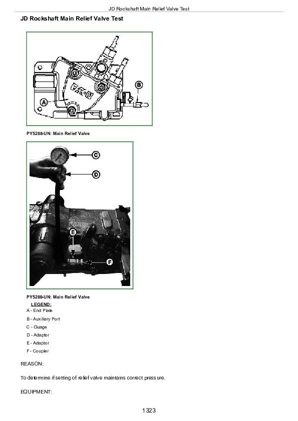
JD Rockshaft Main Relief Valve Test................1323
Group 25: Hydraulic Tests—With SCV................1243
Hydraulic System Tests—With SCV................1327
Pump Flow Test—With SCV................1329
Main Relief Valve Test—With SCV................1331
SCV Leakage Test................1333
Group 18: Hydraulic Tests—With Mid Mount Control Valve................1243
Hydraulic System Tests—With Mid Mount Control Valve................1336
Pump Flow Test—With Mid Mount Control Valve................1337
Main Relief Valve Test—With Mid Mount Control Valve................1339
Mid Mount Control Valve Leakage Test................1341
Group 30: Hydraulic Tests - All................1243
MITA Rockshaft Leakage Test................1344
JD Rockshaft Leakage Test................1346
Rockshaft Lift Cycle Test................1348
Group 40: Adjustments................1243
Rockshaft Sensing Lever Friction Adjustment - MITA Rockshaft................1351
Control of Assembly of Reaction Spring- MITA Rockshaft................1352
Measurement Control of Push rod- MITA Rockshaft................1354
Adjustment of Position Control Lever- MITA Rockshaft................1355
Adjustment Of Draft Control Lever- MITA Rockshaft................1356
Rockshaft Lever Friction Adjustment- JD Rockshaft................1357
Rockshaft Position-Sensing Feedback Linkage Adjustment- JD Rockshaft................1358
Rockshaft Draft-Sensing Feedback Linkage Adjustment- JD Rockshaft................1362
Mid Mount Control Valve Joystick Cable Adjustment................1364
Group 45: Hydraulic Schematics................1244
Hydraulic Circuit Symbols................1368
John Deere 5103, 5203, 5303, and 5403 USA Tractors 5103, 5203, 5303, and 5403 Australia Tractors 5303 and 5403 Latin America Tractors Diagnosis and Repair Service Manual (TM4829)


