John Deere Tractors 5203S, 5310, 5310S Diagnostic & Repair Service Manual (TM4898)
Catalog:
Model:
Complete All Inclusive Technical Manual with electrical wiring diagrams for John Deere India Tractors 5203S, 5310, 5310S, with all the shop information to maintain, diagnostic, repair, service like professional mechanics (Diagnosis, Operation, Tests, Repair, Service, Troubleshooting).
John Deere Tractors 5203S, 5310, 5310S technical diagnostics repair service manual includes:
* Numbered table of contents easy to use so that you can find the information you need fast.
* Detailed sub-steps expand on repair procedure information
* Numbered instructions guide you through every repair procedure step by step.
* Troubleshooting and electrical service procedures are combined with detailed wiring diagrams for ease of use.
* Notes, cautions and warnings throughout each chapter pinpoint critical information.
* Bold figure number help you quickly match illustrations with instructions.
* Detailed illustrations, drawings and photos guide you through every procedure.
* Enlarged inset helps you identify and examine parts in detail.
tm4898 - 5310 And 5203S Tractors Technical Manual.pdf
Total Pages: 1,363 pages
File Format: PDF (bookmarked, ToC, Searchable, Printable, high quality)
Language: English
MAIN SECTIONS
Foreword
General Information
Safety
General Specifications
Fuel and Lubricants
Serial Number Locations
Features and Accessories
Engine Repair
Engine
Cylinder Head and Valves
Cyl. Block, Liners, Pistons & Rods
Crankshaft, Main Bearings and Flywheel
Camshaft and Timing Gear Train
Lubrication System
Cooling System
Fuel and Air Repair
Fuel System
Air Intake and Exhaust System
Speed Control Linkage
Electrical Repair
Battery, Starter and Alternator
Electrical System Components
Wiring Harness
Power Train Repair
Clutch Housing
Clutch Assembly- CollarShift Transmissions
Transmission
Rear PTO Drive Shaft
Differential
Final Drives
Steering and Brake Repair
Steering Repair
Brake Repair
Hydraulic Repair
Hydraulic Pump and Filter
Rockshaft
Selective Control Valve (SCV)
Miscellaneous Repair
Front Axle
Wheels
3-Point Hitch
Operator Station Repair
Seat and Support
Operator Platform
Fenders
Operational Checkout Procedures
Operational Checkout Procedures
Engine Operation, Test and Adjustments
Component Location
Theory of Operation
Diagnosis, Tests and Adjustments
Fuel/Air Operation, Test and Adjustments
Component Location
Theory of Operation (5310 and 5203S)
Theory of Operation (5310 S)
Diagnosis, Tests and Adjustments
Electrical Operation, Test and Adjustments (5310 S)
Component Location
Theory of Operation
Wiring Schematics
Diagnosis, Test and Adjustment
Electrical Operation, Test and Adjustments (5310 and 5203S)
Component Location
Theory of Operation
Wiring Schematics
Diagnosis, Test and Adjustment
Power Train Operation, Tests and Adjustments
Component Location-CollarShift Transmission
Theory of Operation-CollarShift Transmission
Diagnosis, Tests, and Adjustments-CS Transmission
Steering and Brake Operation, Test & Adjustments
Component Location
Theory of Operation
Diagnosis, Tests and Adjustments
Hydraulic System Operation, Test and Adjustments
Component Location
Theory of Operation
Diagnosis
Hydraulic Tests-With SCV
Hydraulic Tests
Adjustments
Hydraulic Schematics
TABLE OF CONTENTS
Section 10: General Information................27
Group 05: Safety................27
Recognize Safety Information................30
Understand Signal Words................31
Follow Safety Instructions................32
Handle Fluids Safely-Avoid Fires................33
Prevent Battery Explosions................34
Prepare for Emergencies................35
Prevent Acid Burns................36
Service Cooling System Safely................38
Avoid High-Pressure Fluids................39
Park Machine Safely................40
Support Machine Properly................41
Wear Protective Clothing................42
Work in Clean Area................43
Service Machines Safely................44
Work in Ventilated Area................45
Illuminate Work Area Safely................46
Replace Safety Signs................47
Use Proper Lifting Equipment................48
Service Tires Safely................49
Avoid Harmful Asbestos Dust................50
Avoid Heating Near Pressurized Fluid Lines................51
Remove Paint Before Welding or Heating................52
Use Proper Tools................53
Dispose of Waste Properly................54
Live With Safety................55
Group 10: General Specifications................876
LLL&T-John Deere 5310 S Tractor{pgNO}27T-John Deere 5310 S Tractor{pgNO}58T-John Deere 5310 S Tractor................56
LL&T-John Deere 5310 Tractor{pgNO}27T-John Deere 5310 Tractor................60
LL&T-John Deere 5203S Tractor{pgNO}27T-John Deere 5203S Tractor................62
Ground Speed Estimates................64
Service Recommendations for O-Ring Boss Fittings................66
Service Recommendations for Flat Face O-Ring Seal Fittings................68
Metric Bolt and cap screw Torque Values................70
Unified Inch Bolt and cap screw Torque Values................72
Group 20: Fuel and Lubricants................28
Diesel Fuel................76
Fuel Storage................78
Do Not Use Galvanized Containers................79
Fill Fuel Tank................80
Diesel Engine Oil................82
Diesel Engine Coolant................83
Transmission and Hydraulic Oil................84
Grease (Specific Application)................85
Grease................86
Lubricant Storage................87
Group 25: Serial Number Locations................28
Serial Numbers................89
Product Identification Number Location................90
Engine Serial Number Location................91
Fuel Injection Pump Serial Number Location................92
Alternator Serial Number Location................93
Power Steering Valve Serial Number Location................94
Starter Serial Number Location................95
Transmission Serial Number Location................96
Front Axle Serial Number Location................97
Group 30: Features and Accessories................100
Features and Accessories................100
Standard Features................102
Field Installed Optional Kits and Accessories................104
Section 20: Engine Repair................105
Group 05: Engine................105
Service Equipment and Tools................652
Specifications................876
John Deere Engine Repair-Use CTM8................114
Remove Engine (5310 and 5203S)................115
Install Engine (5310 and 5203S)................122
Remove Engine (5310 S)................129
Install Engine (5310 S)................137
Engine Disassembly Sequence................144
Sealant Application Guidelines................146
Engine Re-Assembly Sequence................147
Engine break-in guidelines................149
Perform engine break-in................150
Diesel Engine Break-In Oil................151
Group 10: Cylinder Head and Valves................105
Special or Essential Tools................877
Specifications................876
Torques for Hardware................347
Cylinder Head - Exploded View................201
Check Valve Lift................162
Remove Cylinder Head................163
Clean Injection Nozzle Bores................165
Valve Actuating Parts................166
Remove Valves and Valve Springs................167
Checking Cylinder Head Flatness................168
Clean Valve Guides................169
Measure Valve Guides................170
Clean and Inspect valve Seats................172
Lapping Valve Seats................173
Check Valve Recess................174
Remove Valve Seat Inserts................175
Valve Seat Insert Installation................177
Grind Valves................178
Check Valve Spring Tension................179
Inspect Valve Rotators................180
Install Valves................181
Install Cylinder Head................183
Torque Turn Tightening Method................185
Checking Rocker Arm Shaft................186
Reassembling Rocker Arm Shaft................188
Install Rocker Arm Assembly................189
Valve Clearance................190
Valve Adjustment Sequence................191
Install Rocker Arm Cover................192
Final Work................193
Group 15: Cyl. Block, Liners, Pistons & Rods................106
Special or Essential Tools................877
Specifications................876
Torques for Hardware................347
Exploded View................201
Connecting Rods - General Information................202
Remove Pistons and Connecting Rods................204
Measure Cylinder Liner Bore................206
Remove Cylinder Liners................207
Cylinder Liner Deglazing................208
Cylinder Block Cleaning................209
Check Piston Cooling Jets................210
Cam Follower Bore Measure................211
Measure Camshaft Bore................212
Remove Camshaft Bushing................213
Install Camshaft Bushing................214
Measure Crankshaft Bore................215
Replace Crankshaft Bearing Caps................216
Cylinder Block Top Desk Flatness................217
Measure Cylinder Liner Protrusion................218
Liner Packing Installation................220
Liner O-Ring Installation................221
Install Cylinder Liners................222
Measure Connecting Rod Bearing................223
Rod Bearing Clearance................225
Measure Connecting Rod Bushing................226
Replace Connecting Rod Bushing (3029D)................227
Replace Connecting Rod Bushing (3029T)................228
Measure Piston Pin................231
Clean and Inspect Pistons................232
Measure Piston Pin Bore................233
Piston Top Ring Groove................234
Second and Third Piston Ring Grooves................235
Piston Head and Skirt Checking................236
Install Piston Rings................237
Piston Rings Staggering................239
Piston/Liner Set Information................240
Assemble Piston and Connecting Rod................241
Install Piston and Connecting Rod................243
Measure Piston Protrusion................246
Complete Final Assembly (5310 and 5203S)................247
Complete Final Assembly (5310 S)................250
Group 20: Crankshaft, Main Bearings and Flywheel................107
Special or Essential Tools................877
Specifications................876
Torques For Hardware................379
Remove Crankshaft Pulley................257
Install Crankshaft Pulley................258
Flywheel Removal................259
Flywheel Ring Gear Replacement................260
Install Ball Bearing................261
Install Flywheel................262
Remove Crankshaft Rear Oil Seal................263
Flywheel Housing Replacement................265
Install Oil Seal/Wear Sleeve................267
Crankshaft End Play Measure................268
Remove Crankshaft................270
Crankshaft Inspection................271
Check Crankshaft Journal Diameter................272
Determine Crankshaft Main Bearing Clearance Using PLASTIGAGEPLASTIGAGE is a trademark of DANA Corp.................108
Regrind Crankshaft................275
Crankshaft Regrinding Guidelines................276
Micro-Finishing Specifications................876
Replace Crankshaft Gear................278
Install Main Bearing Inserts................280
Install 2-Piece Thrust Bearing................281
Crankshaft Installation................282
Group 25: Camshaft and Timing Gear Train................108
Special or Essential Tools................877
Specifications................876
Torques for Hardware................347
Remove Crankshaft Front Oil Seal................289
Remove Timing Gear Cover................290
Measure Timing Gear Backlash................291
Camshaft End Play Measure................292
Remove Camshaft................293
Measure Camshaft Journal................294
Measure Height of Cam Lobe................295
Replace Camshaft Gear................296
Install Camshaft................297
Check Cam Follower................298
Idler Gear End Play Measure................299
Remove Front Plate................300
Idler Gear Bushing and Shaft Measure................302
Idler Gear Bushing Replacement................303
Remove Idler Shaft................304
Install Idler Shaft Spring Pin................305
Install Idler Shafts................306
Install Front Plate................307
Install Upper Timing Gear Train................309
Install Lower Timing Gear Train................311
Install Oil Deflector................312
Timing Gear Cover Identification................313
Install Timing Gear Cover................314
Install Crankshaft Front Oil Seal................316
Install Wear Ring................317
Install Auxiliary Equipment................318
Group 30: Lubrication System................109
Special or Essential Tools................877
Specifications................876
Torques for Hardware................347
Oil Cooler Identification................323
Remove Oil Cooler................324
Replace Oil Cooler Nipple................325
Install Oil Cooler................326
Replace Oil Cooler/Filter Bracket on Engine with Auxiliary Drive................327
Remove Oil Pressure Regulating Valve................329
Replace Oil Pressure Regulating Valve Seat................330
Install Oil Pressure Regulating Valve................331
Replace Oil Dipstick Guide................332
Replace Oil By-Pass Valve................333
Replace Oil Pump Strainer................334
Remove Oil Pump................335
Oil Pump Gear Axial Clearance................336
Oil Pump Gear Radial Clearance................337
Oil Pump Specifications................876
Oil Pump Installation................339
Install Oil Pan................342
Group 35: Cooling System................110
Special or Essential Tools................877
Specifications................876
Torques for Hardware................347
Remove and Inspect Radiator................348
Water Pump - Exploded View................352
Remove Water Pump................353
Disassemble Water Pump................354
Assemble Water Pump................356
Install Water Pump................359
Inspect Thermostat................360
Cooling System Deaeration................362
Check Fan/Alternator Belt Tension................363
Install Fan................365
Install Radiator................367
Replace Thermostat................369
Section 30: Fuel and Air Repair................372
Group 05: Fuel System................372
Special or Essential Tools................877
Self-Manufactured Tool Template For Front Plate Replacement................377
Specifications................876
Torques For Hardware................379
Injection Pump, Nozzle and Governor Repair-Use CTM8................380
Remove, Inspect and Install Fuel Tank................381
Replace Fuel Filter Inserts (5310 and 5203S)................384
Replace Fuel Filter (5310 S)................385
Remove and Install Fuel Filter Assembly (5310 and 5203S)................386
Remove and Install Fuel Filter/Primer Pump Assembly (5310 S)................388
Group 10: Air Intake and Exhaust System................372
Remove, Inspect, and Install Air Cleaner Elements................391
Check Air inlet Pipe (5310 and 5203S)................393
Check Air inlet Pipe (5310 S)................394
Exhaust Manifold Inspection................395
Turbocharger Cut-Away View (Borge Warner)................396
Check Radial Clearance................398
Check Axial Clearance................399
Repair Turbocharger................400
Prelube Turbocharger................401
Install Turbocharger................402
Turbocharger Break-In................405
Recommendations for Turbocharger Use................406
Group 15: Speed Control Linkage................372
Inspect and Repair Speed Control Linkage................409
Section 40: Electrical Repair................411
Group 05: Battery, Starter and Alternator................411
Starter Repair-Use CTM77................413
Remove and Install Battery................414
Remove and Install Starter................416
Replace Alternator/Regulator................418
Group 10: Electrical System Components................411
Service Equipment and Tools................652
Other Material................693
Replace Air Filter Restriction Sensor................423
Replace Coolant Temperature Sender................424
Replace Engine Speed Sensor................425
Replace Engine Oil Pressure Sensor................426
Replace Key Switch................427
Replace Light Switch................428
Replace Turn Signal Controller................429
Replace Instrument Panel................430
Replace Neutral Start Switch................433
Replace Fuel Level Sender................434
Replace 7 Pin Connector................436
Group 15: Wiring Harness................411
Special or Essential Tools................877
Service Parts Kits................677
Remove Connector Body from Blade Terminals................440
Replace WEATHER PACK WEATHER PACK is a trademark of Packard Electric. Connector................411
Install WEATHER PACK WEATHER PACK is a trademark of Packard Electric. Contact................411
Replace Tractor Wiring Harness................445
Section 50: Power Train Repair................448
Group 05: Clutch Housing................448
Service Equipment and Tools................652
Other Material................693
Specifications................876
Separate Engine from Clutch Housing (5310 and 5203S)................455
Install Engine to Clutch Housing (5310 and 5203S)................461
Separate Engine from Clutch Housing (5310 S)................467
Install Engine to Clutch Housing (5310 S)................473
Replace Clutch Housing Seal................479
Inspect and Repair Clutch Pedal and Linkage................481
Group 10: Clutch Assembly- CollarShift Transmissions................448
Essential Tools................877
Service Equipment and Tools................652
Other Material................693
Specifications................876
Remove and Install Clutch Assembly................488
Disassemble and Inspect Clutch Assembly................491
Assemble Clutch Assembly................499
Traction Clutch Finger Adjustment................505
PTO Clutch Finger Adjustment................507
Remove and Inspect Clutch Release Mechanism and Shafts................509
Install Clutch Release Mechanism and Shafts................513
Group 15: Transmission................448
Specifications................876
Separate Clutch Housing from Transmission................518
Install Clutch Housing to Transmission................523
Inspect and Repair Gear and Range Shift Levers................528
Remove Transmission................532
Disassemble and Inspect Transmission................535
Assemble Transmission................544
Install Transmission................551
Disassemble, Inspect and Assemble Gear Shift Shaft Assemblies................559
Disassemble, Inspect, and Assemble Transmission Top Shaft-CollarShift Transmission................561
Disassemble, Inspect, and Assemble Range Reduction Shaft................564
Disassemble, Inspect and Assemble Driven Shaft................566
Remove, Inspect, and Install Range Gears................568
Remove, Inspect, and Install Reverse Idler Shaft................570
Group 20: Rear PTO Drive Shaft................449
Other Material................693
Specifications................876
Remove, Inspect and Install Rear PTO Lever and Linkage................575
Remove and Install Standard Rear PTO Drive Shaft Assembly................577
Disassemble, Inspect and Assemble Standard Rear PTO Drive Shaft Assembly................579
Remove, Inspect and Install 540/540E Shift Lever and Linkage (Optional)................582
Remove and Install 540/540E Rear PTO Drive Shaft Assembly (Optional)................584
Disassemble, Inspect and Assemble Rear 540/540E PTO Drive Shaft Assembly (Optional)................586
Group 25: Differential................449
Essential Tools................877
Service Equipment and Tools................652
Other Material................693
Specifications................876
Service Parts Kits................677
Remove and Install Differential Assembly................596
Disassemble, Inspect, and Assemble Differential Assembly................598
Remove and Inspect Differential Drive Shaft................600
Install Differential Drive Shaft................604
Remove, Inspect, and Install Differential Lock Assembly (Optional 5203S)................609
Differential Cone Point Adjustment................611
Differential Backlash Adjustment................613
Group 30: Final Drives................449
Service Equipment and Tools................652
Other Material................693
Specifications................876
Remove and Install Final Drive Assembly................619
Remove and Inspect Planetary Drive Assembly................621
Install Planetary Drive Assembly................624
Remove, Inspect, and Install Axle Shaft Assembly................627
Section 60: Steering and Brake Repair................631
Group 05: Steering Repair................631
Other Material................693
Specifications................876
Service Parts Kits................677
Remove and Install Steering Column and valve................636
Disassemble and Inspect Steering valve................638
Assemble Steering valve................642
Remove and Install Steering Cylinder-2WD Axle................647
Disassemble, Inspect and Assemble Steering Cylinder-2WD Axle................649
Group 10: Brake Repair................631
Service Equipment and Tools................652
Other Material................693
Specifications................876
Remove and Install Brake valve and Pedals................655
Disassemble and Inspect Brake Pedals and valve................657
Brake valve Cross Section................660
Assemble Brake valve................662
Remove and Inspect Brakes................665
Install Brakes................668
Inspect and Replace Brake Hydraulic Lines................671
Section 70: Hydraulic Repair................673
Group 05: Hydraulic Pump and Filter................673
Essential Tools................877
Specifications................876
Service Parts Kits................677
Remove, Inspect, and Install Hydraulic Oil Pick-Up Screen................678
Remove and Install Hydraulic Pump................679
Remove Hydraulic Pump External Components................681
Disassemble and Inspect Hydraulic Pump................682
Assemble Hydraulic Pump................685
Install Hydraulic Pump External Components................687
Remove and Install Hydraulic Oil Filter/Manifold................689
Inspect and Replace Hydraulic Supply and Suction/Return Lines................690
Group 10: Rockshaft................673
Other Material................693
Specifications................876
Remove, Inspect, and Install Rockshaft Control Lever Assembly................695
Remove, Inspect, and Install Rockshaft Control Lever Support Assembly................698
Remove, Inspect and Install Rockshaft Control Linkage................708
Replace Main Relief valve................719
Remove, Inspect and Install Rate-of-Drop valve................721
Replace Rockshaft Control valve................724
Remove and Install Rockshaft Case................728
Remove, Inspect and Install Rockshaft Lift Arms................730
Remove, Inspect and Install Rockshaft Piston and Cylinder................734
Group 15: Selective Control Valve (SCV)................673
Install Single Selective Control Valve (SCV)................741
Install Rear Coupler Bracket................746
Install Hydraulic Hoses................761
Install Second Selective Control Valve (SCV)................755
Assemble Rear Quick Coupler................759
Install Hydraulic Hoses................761
Section 80: Miscellaneous Repair................766
Group 05: Front Axle................766
Specifications................876
Remove and Install Front Axle (5310 and 5203S)................769
Remove and Install Front Axle (5310 S)................772
Inspect and Replace Pivot Pin and Bushings (5310 and 5203S)................775
Inspect and Replace Pivot Pin and Bushings (5310 S)................776
Remove and Install Spindle Assembly (5310 and 5203S)................777
Remove and Install Spindle Assembly (5310 S)................779
Inspect and Replace Spindle Shaft Bushings (5310 and 5203S)................781
Inspect and Replace Spindle Shaft Bushings (5310 S)................782
Group 10: Wheels................766
Specifications................876
Inspect and Replace Front Wheel Bearings................785
Tighten Bolts-Rear Axle (M-14 Bolts)................786
Tighten Bolts-Rear Axle (M-20 Stud) (5310 and 5203S)................787
Tighten Bolts-Rear Axle (M-20 Stud) (5310 S)................788
Group 15: 3-Point Hitch................766
Specifications................876
Inspect and Repair Fixed Draft Links................791
Inspect and Repair Lift Link (5310 and 5203S)................792
Inspect and Repair Lift Link (5310 S)................794
Inspect and Repair Adjustable Lift Link................796
Inspect and Repair Center Link................798
Remove and Install Wagon Hitch and Support................800
Section 90: Operator Station Repair................802
Group 05: Seat and Support................802
Specifications................876
Remove and Install Deluxe Seat and Support................805
Group 15: Operator Platform................802
Specifications................876
Remove and Install Right-Side Platform and Step - Old................808
Remove and Install Left-Side Platform and Step - Old................810
Remove and Install Right-Side Platform and Step - New................813
Remove and Install Left-Side Platform and Step - New................815
Group 20: Fenders................802
Remove and Install Fenders - Old................819
Remove and Install Fenders - New................820
Section 210: Operational Checkout Procedures................822
Group 10: Operational Checkout Procedures................822
Operational Checkout Procedure Information................824
Engine Oil Level and Condition Check................825
Coolant Level and Condition Check................826
Transmission and Hydraulic Oil Check................827
Fan and Belt Check................828
Fuel System Check (5310 and 5203S)................829
Fuel System Check (5310 S)................830
Air Intake System Check................831
Electrical System Check................832
Hydraulic System Check................834
Indicator Lamps Check................835
Engine Start Check................836
Transmission Neutral Start Check................837
Engine Fast and Slow Idle Operation................838
Power Steering Check................839
Differential Lock Check................840
Clutch Check................841
Transmission Shift Check................842
Range Lever Shift Check................843
Brake Check................845
Rockshaft Check................846
Selective Control Valve Check................848
Miscellaneous Checks................850
Section 220: Engine Operation, Test and Adjustments................851
Group 05: Component Location................851
Component Location Information................1303
Engine External Components-Left-Hand Side (5310 and 5203S)................855
Engine External Components-Left-Hand Side (5310 S)................857
Engine External Components-Right-Hand Side (5310 and 5203S)................859
Engine External Components-Right-Hand Side (5310 S)................861
Group 10: Theory of Operation................851
Theory of Operation Information................1307
Engine Lubrication System Operation (5310 and 5203S)................865
Engine Lubrication System Operation (5310 S)................869
Engine Cooling System Operation................873
Group 15: Diagnosis, Tests and Adjustments................851
Specifications................876
Essential Tools................877
Diagnostic Information................1340
Engine Turns Over But Will Not Start or Starts Hard................879
Engine Runs Irregularly or Stalls Frequently................880
Engine Runs Rough................881
Engine Low Power................882
Engine Smokes-Black or Grey................884
Engine Smokes Excessively-White................885
Engine Uses Excess Fuel................886
Engine Has Excess Noise or Vibration................887
Engine Uses Excess Oil or Smokes Blue................888
Engine Has Low Oil Pressure................889
Engine Coolant Operating Temperature Incorrect................890
Oil In Coolant or Coolant in Oil................891
Radiator Bubble Test................892
Cooling System Test................895
Radiator Cap Pressure Test................896
Engine Oil Pressure Test................897
Cylinder Compression Pressure Test (5310 and 5203S)................899
Cylinder Compression Pressure Test (5310 S)................901
Fuel Shut-Off Solenoid Check (5310 S)................903
Throttle Lever Adjustment................904
Fuel Injection Pump Setting (5310 and 5203S)................905
Fuel Injection Pump Timing Adjustment (5310 S)................910
Idle Speed Adjustment (5310 and 5203S)................911
Slow Idle Adjustment (5310 S)................912
Fast Idle Adjustment (5310 S)................914
Valve Clearance Adjustment................916
Fan/Alternator Drive Belt Adjustment................918
Bleeding Fuel System (5310 and 5203S)................920
Bleed Fuel System At Fuel Injection Nozzles................921
Bleeding Fuel System (5310 S)................922
Section 230: Fuel/Air Operation, Test and Adjustments................925
Group 05: Component Location................925
Component Location Information................1303
Fuel System Components (5310 and 5203S)................928
Fuel System Components (5310 S)................930
Air Intake System Components (5310 and 5203S)................932
Air Intake System Components (5310 S)................933
Group 10: Theory of Operation (5310 and 5203S)................925
Theory of Operation Information................1307
Fuel System Operation................951
Fuel Filter Operation................938
Fuel Injection Nozzle Operation................957
Fuel Transfer (Feed) Pump Operation................941
In-Line Fuel Injection Pump Operation................955
Governor Operation (In-Line Pump)................945
Air Intake System Operation................959
Group 10: Theory of Operation (5310 S)................925
Theory of Operation Information................1307
Fuel System Operation................951
Fuel Filter Pump Operation................953
Fuel Injection Pump Operation................955
Fuel Injection Nozzle Operation................957
Air Intake System Operation................959
Turbocharger Operation................961
Check Turbocharger Boost Pressure................962
Diagnosing Turbocharger Malfunctions................963
Group 15: Diagnosis, Tests and Adjustments................925
Diagnostic Information................1340
Fuel/Air Diagnosis, Tests and Adjustments................966
Section 240: Electrical Operation, Test and Adjustments (5310 S)................967
Group 05: Component Location................967
Component Location Information................1303
Engine Electrical Components-Right Hand Side................1071
Engine Electrical Components-Left Hand Side................1072
Dash And Center Control Console Electrical Components................1073
Group 10: Theory of Operation................967
Theory of Operation Information................1307
Fuse Block and Fuses................1077
Relays................1078
Starting System Operation-Normal................979
Starting System Operation-Bypass Attempt................981
Charging System Operation................1081
Lighting System Operation-Turn Signals................1083
Lighting System Operation-Warning Lights................987
Lighting System Operation-Tail Lights................1087
Lighting System Operation-Headlights and Instrument Lights................1089
Instrument Panel System Operation-Tachometer/Hour Meter................1091
Instrument Panel System Operation-Fuel Gauge................1093
Instrument Panel System Operation-Temperature Gauge................1095
Air Filter Restriction Indicator Operation................1097
7-Pin Trailer Outlet Connector Operation................1099
Horn Operation................1101
Flood Light................1102
Group 20: Wiring Schematics................967
Schematic Information................1105
Component Identification Table................1106
Electrical Schematic................1108
Group 15: Diagnosis, Test and Adjustment................967
Diagnostic Information................1340
Starting System Test Points-Normal Operation................1112
Charging System Test Points................1117
Lighting System Test Points-Turn Signals and Warning Lights................1122
Lighting System Test Points-Rear Flood Light................1130
Lighting System Test Points-Headlights and Instrument Lights................1133
Instrument Panel System Test Points-Tachometer/Hourmeter................1141
Instrument Panel System Test Points-Fuel Gauge................1143
Instrument Panel System Test Points-Temperature Gauge................1147
Instrument Panel System Test Points-Oil Pressure................1152
Air Filter Restriction Test Points................1157
Horn Test Points................1162
Section 250: Electrical Operation, Test and Adjustments (5310 and 5203S)................1067
Group 05: Component Location................1067
Component Location Information................1303
Engine Electrical Components-Right Hand Side................1071
Engine Electrical Components-Left Hand Side................1072
Dash And Center Control Console Electrical Components................1073
Group 10: Theory of Operation................1067
Theory of Operation Information................1307
Fuse Block and Fuses................1077
Relays................1078
Starting System Operation................1079
Charging System Operation................1081
Lighting System Operation-Turn Signals................1083
Lighting System Operation-Hazard Warning Lights................1085
Lighting System Operation-Tail Lights................1087
Lighting System Operation-Headlights and Instrument Lights................1089
Instrument Panel System Operation-Tachometer/Hour Meter................1091
Instrument Panel System Operation-Fuel Gauge................1093
Instrument Panel System Operation-Temperature Gauge................1095
Air Filter Restriction Indicator Operation................1097
7-Pin Trailer Outlet Connector Operation................1099
Horn Operation................1101
Flood Light................1102
Group 20: Wiring Schematics................1067
Schematic Information................1105
Component Identification Table................1106
Electrical Schematic................1108
Group 15: Diagnosis, Test and Adjustment................1067
Diagnostic Information................1340
Starting System Test Points-Normal Operation................1112
Charging System Test Points................1117
Lighting System Test Points-Turn Signals and Warning Lights................1122
Lighting System Test Points-Rear Flood Light................1130
Lighting System Test Points-Headlights and Instrument Lights................1133
Instrument Panel System Test Points-Tachometer/Hourmeter................1141
Instrument Panel System Test Points-Fuel Gauge................1143
Instrument Panel System Test Points-Temperature Gauge................1147
Instrument Panel System Test Points-Oil Pressure................1152
Air Filter Restriction Test Points................1157
Horn Test Points................1162
Battery Voltage and Specific Gravity Tests................1165
Charge Battery................1167
Battery Load Test................1169
Starter AMP Draw/RPM Test................1171
Starter No-Load AMP Draw/RPM Test................1173
Alternator/Regulator Test................1175
Starter Solenoid Test................1177
Starter Relay Test................1178
Plug-In Relay Test................1179
Diode Pack Test................1181
Fuse Test................1183
Neutral Start Switch Test................1184
Turn Signal Controller (Flasher) Test................1185
Section 260: Power Train Operation, Tests and Adjustments................1186
Group 05: Component Location-CollarShift Transmission................1186
Component Location Information................1303
Power Train Components-(CollarShift )................1190
Clutch Components-Dual................1191
Transmission Components-CollarShift................1193
Final Drive Components................1195
Rear PTO Components................1196
Rear 540/540E PTO Components................1197
Group 10: Theory of Operation-CollarShift Transmission................1186
Theory of Operation Information................1307
Clutch Operation-Dual Clutch................1200
Transmission Lubrication System................1208
CollarShift Transmission-Gear Shift Power Flow................1210
CollarShift Transmission-Range Shift Power Flow................1212
Rear PTO Operation................1217
Rear PTO Operation................1217
Rear 540/540E PTO Operation................1216
Rear PTO Operation................1217
Differential Power Flow................1219
Differential Power Flow................1219
Differential Lock Operation (Optional 5203S)................1220
Final Drive Operation................1222
Group 15: Diagnosis, Tests, and Adjustments-CS Transmission................1186
Diagnostic Information................1340
Isolate the Problem Area................1226
Traction Clutch Slips................1228
Traction Clutch Dragging................1229
Traction Clutch Does Not Engage................1230
Traction Clutch Grabs................1231
Traction Clutch Squeaks................1232
Traction Clutch Does Not Release................1233
Traction Clutch Chatters................1234
Traction Clutch Rattles................1235
Traction Clutch Engagement Is Noisy................1236
Excessive Vibration in Traction Clutch................1237
Clutch Pedal Does Not Return................1238
Clutch Pedal Loose................1239
Clutch Pedal Pulsates................1240
Jerky or Rough Transmission of Power................1241
Low Transmission Oil Level (Excessive Oil Leakage)................1242
Gears Clash, Shift Hard, or Will Not Engage................1243
Two Speeds Engage Together................1244
Transmission Will Not Stay in Gear................1245
Transmission Noisy................1246
PTO Noisy................1247
PTO Hard to Engage................1248
PTO Will Not Operate................1249
PTO Will Not Stay Engaged................1250
Excessive Differential Noise................1251
Differential Does Not Work................1252
No Differential Lock................1253
Differential Chatters................1254
Axle Noise................1255
Axle Shaft Will Not Turn................1256
Check and Adjust Clutch Pedal Free Play................1257
PTO Clutch Lever Adjustment................1259
Section 270: Steering and Brake Operation, Test Section 270: Steering and Brake Operation, Test & Adjustments{pgNO}1262 Adjustments................1262
Group 05: Component Location................1262
Component Location Information................1303
Steering System Components................1265
Brake System Components................1267
Group 10: Theory of Operation................1262
Theory of Operation Information................1307
Steering System Operation................1271
Steering valve Operation-Neutral and Manual Turning................1273
Steering valve Operation-Power Turning................1275
Brake System Operation................1277
Brake valve Operation................1279
Group 15: Diagnosis, Tests and Adjustments................1262
Diagnostic Information................1340
Isolate the Problem-Steering System................1285
Steering Sluggish or Loss of Steering................1286
Isolate the Problem-Brakes................1287
Excessive Brake Pedal Leak-Down................1288
Excessive Brake Chatter................1289
Steering Pump Flow Test................1363
Steering valve Relief Test................1292
Steering Cylinder Leakage Test................1293
Steering valve Leakage Test................1294
Adjusting Toe-In................1296
Brake Pedal Adjustment................1297
Bleed Brake System................1299
Section 280: Hydraulic System Operation, Test and Adjustments................1300
Group 05: Component Location................1300
Component Location Information................1303
Hydraulic System Components................1304
Group 10: Theory of Operation................1300
Theory of Operation Information................1307
Hydraulic System Operation................1308
Hydraulic Filter Operation................1311
Hydraulic Pump Operation................1313
Rockshaft Control Valve Operation-Neutral Position................1315
Rockshaft Control Valve Operation-Raise Position................1317
Rockshaft Control Valve Operation-Lower Position................1319
Flow Control Valve Operation (FCV) -Neutral Position................1321
Flow Control Valve Operation (FCV) -Delivery Position................1323
Flow Control Valve Operation (FCV) -Discharge Position................1325
Selective Control Valve-Neutral Position................1327
Selective Control Valve-Retract Position................1329
Selective Control Valve-Extend Position................1331
Selective Control Valve-Float Position................1333
Surge (Safety) Relief valve Operation................1335
Rate-of-Drop valve (Implement Lock) Operation................1337
Group 15: Diagnosis................1300
Diagnostic Information................1340
Preliminary Hydraulic System Inspection................1341
Entire Hydraulic System Fails to Function/No Hydraulic Pump Output................1342
Insufficient Pump Delivery................1343
Hydraulic Functions Too Slow................1344
Excessive Pump Pressure................1345
Slow Hydraulic Pump Response................1346
Excessive Pump Noise During Operation................1347
Rockshaft Does Not Lift or Lifts Slowly................1348
Rockshaft Does Not Lower or Lowers Slowly................1349
Neutral Position Unstable, Rockshaft Drops after Engine Shut Down................1350
Group 17: Hydraulic Tests-With SCV................1301
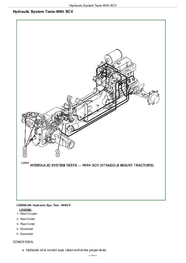
Hydraulic System Tests-With SCV................1353
Pump Flow Test-With SCV................1355
Main Relief Valve Test-With SCV................1357
SCV Leakage Test................1359
Group 16: Hydraulic Tests................1301
Hydraulic System Tests................1362
Pump Flow Test................1363
Main Relief valve Test................1365
Rockshaft Leakage Test................1367
Rockshaft Lift Cycle Test................1368
Group 20: Adjustments................1301
Rockshaft Sensing Lever Friction Adjustment................1371
Control of Assembly of Reaction Spring................1372
Measurement Control of Push rod................1374
Adjustment of Position Control Lever................1375
Adjustment Of Draft Control Lever................1376
Group 21: Hydraulic Schematics................1301
Hydraulic Circuit Symbols................1379
John Deere Tractors 5203S, 5310, 5310S Diagnostic & Repair Service Manual (TM4898)


