John Deere Tractors 5055E, 5065E, 5075E, 5078E, 5085E, 5090E Diagnosis and Tests Service Technical Manual (TM801619)
Catalog:
Model:
Complete Diagnosis & Tests Technical Manual with electrical wiring diagrams for John Deere Tractors 5090E, 5085E, 5078E, 5075E, 5065E, 5055E (2WD or MFWD - PIN Prefix BM), with all the technical information to maintain, diagnose, and test like professional mechanics.
John Deere Tractors 5055E, 5065E, 5075E, 5078E, 5085E, 5090E workshop Diagnosis & Tests technical manual includes:
* Numbered table of contents easy to use so that you can find the information you need fast.
* Detailed sub-steps expand on repair procedure information
* Numbered instructions guide you through every repair procedure step by step.
* Troubleshooting and electrical service procedures are combined with detailed wiring diagrams for ease of use.
* Notes, cautions and warnings throughout each chapter pinpoint critical information.
* Bold figure number help you quickly match illustrations with instructions.
* Detailed illustrations, drawings and photos guide you through every procedure.
* Enlarged inset helps you identify and examine parts in detail.
tm801619 English - 5055E, 5065E, 5075E, 5078E, 5085E and 5090E Tractors — Diagnosis and Tests Technical Manual - (World Edition) Technical Manual.pdf
tm801628 French - Manuel technique de diagnosticTracteurs 5055E, 5065E, 5075E, 5078E, 5085E et 5090E -: (Édition mondiale)
tm801654 Portuguese - Tratores 5055E, 5065E, 5075E, 5078E (N.S. -018722), 5085E e 5090E (N.S. -003438) — Manual Técnico de Diagnóstico -: (Edição Mundial)
Total Pages: 1,613 pages
File Format: PDF (bookmarked, ToC, Searchable, Printable)
Language: English
MAIN SECTIONS
Foreword
General Information
Safety
General References
References for Technical Information
Observable Symptoms and System Diagnostics
Engine
Fuel and Air Intake
Electrical System - 5055E and 5065E
Electrical System - 5075E
Electrical System - 5078E, 5085E and 5090E - Open Operator's Platform
Electrical System - 5078E, 5085E and 5090E - Cab
Drive Train
Steering and Brakes
Hydraulic System
Cab
Engine
General Information
Theory of Operation
Diagram
Tests for Diagnostics and Adjustments
Information on Engine Components
General Information
Engine Components
Fuel System, Air Intake, Cooling and Exhaust Systems
General Information
Theory of Operation
Schematic
Tests for Diagnostics and Adjustments
Fuel System, Cooling, Air Intake and Exhaust System Component Information
General Information
Fuel System Components
Air Intake System Components
Cooling System Components
Electrical System - 5055E and 5065E
General Information
Operational and Preliminary Checks
Theory of Operation
Schematic
Diagnostic Tests and Adjustments
Electrical System - 5075E
General Information
Operational and Preliminary Checks
Identification of Type
Theory of Operation
Schematic
Diagnostic Tests and Adjustments
Electrical System - 5078E, 5085E and 5090E - Open Operator's Platform
General Information
Operational and Preliminary Checks
Theory of Operation
Schematic
Diagnostic Tests and Adjustments
Electrical System - 5078E, 5085E and 5090E - Cab
General Information
Operational and Preliminary Checks
Theory of Operation
Schematic
Diagnostic Tests and Adjustments
Information on Electrical Components - 5055E and 5065E
Wiring Harnesses
Connectors
Information on Electrical Components - 5075E
Wiring Harnesses
Connectors
Information on Electrical Components - 5078E, 5085E and 5090E - Open Operator's Platform
Wiring Harnesses
Connectors
Electrical Components Information - 5078E, 5085E and 5090E - Cab Tractors
Wiring Harnesses
Connectors
Drive Train
General Information
Theory of Operation
Tests for Diagnostics and Adjustments
Drive Train Components Information
General Information
Drive Train Components
Steering and Brakes
General Information
Theory of Operation
Tests for Diagnostics and Adjustments
Steering and Brake Components Information
Steering System Components
Brake Components
Hydraulic System
General Information
Operational and Preliminary Checks
Identification of Type
Theory of Operation - A-Type
Theory of Operation - B-Type
Theory of Operation - Type C
Theory of Operation - Type D
Hydraulic Schematics
Diagnostic Tests and Adjustments-A-Type
Diagnostic Tests and Adjustments-B-Type
Diagnostic Tests and Adjustments-C-Type
Diagnostic Tests and Adjustments-D-Type
Information on Hydraulic Components
Hydraulic Components
Cab
General Information
Operational and Preliminary Checks
Theory of Operations
Schematic
Diagnostic Tests and Adjustments
Information on Cab Components
Cab Components
TABLE OF CONTENTS
Section 210: General Information................34
Group 05A: Safety................34
Recognize Safety Information................37
Understand Signal Words................38
Follow Safety Instructions................39
Prevent Machine Runaway................40
Handle Fluids Safely—Avoid Fires................41
Prevent Battery Explosions................42
Prepare for Emergencies................43
Handling Batteries Safely................44
Service Cooling System Safely................46
Handle Chemical Products Safely................47
Park Machine Safely................48
Support Machine Properly................49
Wear Protective Clothing................50
Work in Clean Area................51
Service Machines Safely................52
Work In Ventilated Area................53
Illuminate Work Area Safely................54
Replace Safety Signs................55
Use Proper Lifting Equipment................56
Wait Before Opening High-Pressure Fuel System................231
Avoid High-Pressure Fluids................58
Use Steps and Handholds Correctly................59
Remove Paint Before Welding or Heating................60
Avoid Heating Near Pressurized Fluid Lines................61
Keep ROPS Installed Properly................62
Service Tires Safely................63
Avoid Harmful Asbestos Dust................64
Practice Safe Maintenance................65
Use Proper Tools................66
Dispose of Waste Properly................67
Live With Safety................68
Group 05B: General References................35
Summary of References................1529
Information Available in Sections, Groups and Subgroups................71
Trademarks................72
Basic Diagnostic Philosophy................73
Regions and Countries................76
Glossary of Terms................77
Group 05C: References for Technical Information................35
Metric Bolt and Screw Torque Values................81
Unified Inch Bolt and Screw Torque Values................83
Face Seal Fittings Assembly and Installation—All Pressure Applications................86
Metric Face Seal and O-Ring Stud End Fitting Torque Chart—Standard Pressures................87
Metric Face Seal and O-Ring Stud End Fitting Torque Chart—High Pressure Applications................89
SAE Face Seal and O-Ring Stud End Fitting Torque Chart—Standard Pressures................91
SAE Face Seal and O-Ring Stud End Fitting Torque Chart—High Pressure Applications................93
Four Bolt Flange Fittings Assembly and Installation—All Pressure Applications................95
SAE Four Bolt Flange Cap Screw Torque Values—Standard Pressure Applications................96
SAE Four Bolt Flange Cap Screw Torque Values—High Pressure Applications................97
External Hexagon Port Plug Torque Chart................98
Section 212: Observable Symptoms and System Diagnostics................100
Group 20: Engine................100
Engine Problems................103
Group 30: Fuel and Air Intake................100
Problems in Fuel System, Air Intake, Cooling and Exhaust Systems................106
Group 40A: Electrical System - 5055E and 5065E................100
Electrical System Problems - 5055E and 5065E................108
Group 40B: Electrical System - 5075E................100
Electrical System Problems - 5075E................111
Group 40C: Electrical System - 5078E, 5085E and 5090E - Open Operator's Platform................100
Electrical System Problems - 5078E, 5085E and 5090E - Open Operator's Platform................114
Group 40D: Electrical System - 5078E, 5085E and 5090E - Cab................100
Electrical System Problems - 5078E, 5085E and 5090E - Cab................117
Group 50: Drive Train................100
Drive Train Problems................120
Group 60: Steering and Brakes................100
Steering and Brake Problems................122
Group 70: Hydraulic System................1326
Hydraulic System Problems................126
Group 90: Cab................100
Heating, Ventilation and Air Conditioning Problems................130
Section 220: Engine................131
Group 05: General Information................131
Summary of References................1529
Group 20: Theory of Operation................131
Operation of Engine Lubricating System................139
Operation of Engine Lubricating System—Continuation................141
Group 30: Diagram................131
Engine Lubrication System................145
Group 50: Tests for Diagnostics and Adjustments................131
Diagnostic Information................1469
Specifications................149
Essential Tools................150
Engine Does Not Start................151
Engine Operating Irregularly or Stalling Frequently................152
Engine Operating Irregularly................153
Low Engine Power................154
Engine Emits Smoke - Black or Gray................156
Engine Emits Excessive Smoke - White................157
Engine with Excessive Fuel Usage................158
Engine with Noise or Excessive Vibration................159
Engine with Excessive Oil Usage or Blue Smoke................160
Engine with Low Oil Pressure................161
Incorrect Operating Temperature of Engine Coolant................162
Oil in Coolant or Coolant in Oil................163
Radiator Bubble Test................164
Cooling System Test................167
Radiator Cap Pressure Test................168
Engine Oil Pressure Test................169
Cylinder Compression Pressure Test................171
Throttle Lever Adjustment................173
Adjusting Idle Speed................174
Adjusting Injection Pump Synchronization................176
Check and Adjust Valve Play—4-Cylinder Engine................180
Adjusting Valve Play—3-Cylinder Engine................183
Fan/Alternator Drive Belt Adjustment................185
Bleeding Fuel System................231
Bleeding Fuel System at Injection Nozzles................190
Checking Turbocharger Auxiliary Pressure................191
Turbocharger Defect Diagnostics................192
Section 229: Information on Engine Components................193
Group 05: General Information................193
Component Location Information................195
Group 40: Engine Components................193
External Components of 3-Cylinder Engine—Left-Hand Side................198
External Components of 3-Cylinder Engine—Right-Hand Side................200
External Components of 4-Cylinder Engine—Left-Hand Side................202
External Components of 4-Cylinder Engine—Right-Hand Side................203
Section 230: Fuel System, Air Intake, Cooling and Exhaust Systems................204
Group 05: General Information................204
Summary of References................1529
Group 20: Theory of Operation................204
Cooling System Operation—3-Cylinder Engine................209
Cooling System Operation—4-Cylinder Engine................211
Fuel System Operation................213
Fuel Filter Pump Operation................215
Section 239: Fuel System, Cooling, Air Intake and Exhaust System Component Information................237
Group 05: General Information................237
Information on Component Location................1140
Group 40A: Fuel System Components................237
Fuel System - 5055E, 5065E, and 5075E with Bosch Injection Pump................241
Fuel System - 5075E with Stanadyne Injection Pump................242
Fuel System - 5078E, 5085E, and 5090E................243
Group 40B: Air Intake System Components................237
Air Intake System................245
Group 40C: Cooling System Components................237
Water Pump................247
Radiator................248
Engine Water Temperature Sensor................249
Coolant Recovery Tank................250
Thermostat Valve................251
Section 240A: Electrical System - 5055E and 5065E................252
Group 05: General Information................252
Summary of References................1529
Electrical Designators................610
Visually Inspect Electrical System................611
Standard Electrical Symbols................613
Diagnostic Diagram and Information on Symbols in DiagramHow to use an Electrical Diagram................252
Group 10: Operational and Preliminary Checks................252
Battery Test................619
Recharging Battery................620
Important Recommendations about Batteries................621
Testing the Alternator................622
Battery Check................627
Testing Starter Motor Solenoid................630
Starter Motor Test................631
Testing Starter Relay................635
Testing Ignition Switch.................534
Testing the Relay................638
Testing the Diode Block................640
Fuse Test................642
Testing the PTO Sensor................539
Testing the Light Switch................540
Testing Turning Lights Controller................541
Group 20: Theory of Operation................252
20A - Main Power Supply Circuit................252
20B - Engine Start-Up................252
20C - Engine Sensors................252
20D - Engine Air Filter Sensor................252
20E - Power Take-Off................252
20F - Fuel Level................252
20G - Horn................252
20H - Reverse Light and Backup Alarm................252
20I - Brake Lights................253
20J - Turn Signal and Hazard Warning Lights................253
20K - Work Lights................253
Group 30: Schematic................253
30A - Main Power Supply Circuit................253
30B - Engine Start-Up................253
30C - Engine Sensors................253
30D - Engine Air Filter Sensor................253
30E - Power Take-Off................253
30F - Fuel Level................253
30G - Horn................253
30H - Reverse Light and Backup Alarm................253
30I - Brake Lights................253
30J - Turn Signal and Hazard Warning Lights................253
30K - Work Lights................253
Group 50: Diagnostic Tests and Adjustments................253
50B - Engine Start-Up................253
50C - Engine Sensors................253
50D - Engine Air Filter Sensor................253
50E - Power Take-Off................253
50F - Fuel Level................253
50G - Horn................253
50H - Reverse Light and Backup Alarm................253
50I - Brake Lights................253
50J - Turn Signal and Hazard Warning Lights................253
50K - Work Lights................253
Section 240B: Electrical System - 5075E................353
Group 05: General Information................353
Summary of References................1529
Electrical Designators................610
Visually Inspect Electrical System................611
Standard Electrical Symbols................613
Diagnostic Diagram and Information on Symbols in DiagramHow to use an Electrical Diagram................353
Group 10: Operational and Preliminary Checks................353
Battery Test................619
Recharging Battery................620
Important Recommendations about Batteries................621
Testing the Alternator................622
Battery Check................627
Testing Starter Motor Solenoid................630
Starter Motor Test................631
Testing Starter Relay................635
Testing Ignition Switch.................534
Testing the Relay................638
Testing the Diode Block................640
Fuse Test................642
Testing the PTO Sensor................539
Testing the Light Switch................540
Testing Turning Lights Controller................541
Group 15: Identification of Type................353
Identifying Electrical System Type................399
Group 20: Theory of Operation................353
20A - Main Power Supply Circuit - A-Type................353
20B - Main Power Supply Circuit - B-Type................353
20C - Main Power Supply Circuit - C-Type................353
20D - Starting the Engine - A- and B-Type................353
20E - Starting the Engine - C-Type................353
20F - Engine Sensors................353
20G - Engine Air Filter Sensor................354
20H - Power Take-Off................354
20I - Fuel Level................354
20J - Horn................354
20K - Reverse Light and Backup Alarm................354
20L - Brake Lights................354
20M - Turn Signal and Hazard Warning Lights - A-Type................354
20N - Turn Signal and Hazard Warning Lights - B- and C-Type................354
20O - Work Lights - A-Type................354
20P - Work Lights - B-Type................354
20Q - Work Lights - C-Type................354
Group 30: Schematic................354
30A - Main Power Supply Circuit - A-Type................354
30B - Main Power Supply Circuit - B-Type................354
30C - Main Power Supply Circuit - C-Type................354
30D - Starting the Engine - A- and B-Type................354
30E - Starting the Engine - C-Type................354
30F - Engine Sensors................354
30G - Engine Air Filter Sensor................354
30H - Power Take-Off................354
30I - Fuel Level................354
30J - Horn................354
30K - Reverse Light and Backup Alarm................354
30L - Brake Lights................354
30M - Turn Signal and Hazard Warning Lights - A-Type................354
30N - Turn Signal and Hazard Warning Lights - B- and C-Type................354
30O - Work Lights - A-Type................354
30P - Work Lights - B-Type................354
30Q - Work Lights - C-Type................354
Group 50: Diagnostic Tests and Adjustments................354
50D - Starting the Engine - A- and B-Type................354
50E - Starting the Engine - C-Type................354
50F - Engine Sensors................354
50G - Engine Air Filter Sensor................355
50H - Power Take-Off................355
50I - Fuel Level................355
50J - Horn................355
50K - Reverse Light and Backup Alarm................355
50L - Brake Lights................355
50M - Turn Signal and Hazard Warning Lights - A-Type................355
50N - Turn Signal and Hazard Warning Lights - B- and C-Type................355
50O - Work Lights - A-Type................355
50P - Work Lights - B-Type................355
50Q - Work Lights - C-Type................355
Section 240C: Electrical System - 5078E, 5085E and 5090E - Open Operator's Platform................502
Group 05: General Information................502
Summary of References................1529
Electrical Designators................610
Visually Inspect Electrical System................611
Standard Electrical Symbols................613
Diagnostic Diagram and Information on Symbols in DiagramHow to use an Electrical Diagram................502
Group 10: Operational and Preliminary Checks................502
Battery Test................619
Recharging Battery................620
Important Recommendations about Batteries................621
Testing the Alternator................622
Battery Check................627
Testing Starter Motor Solenoid................630
Starter Motor Test................631
Testing Starter Relay................635
Testing Ignition Switch.................534
Testing the Relay................638
Testing the Diode Block................640
Fuse Test................642
Testing the PTO Sensor................539
Testing the Light Switch................540
Testing Turning Lights Controller................541
Group 20: Theory of Operation................502
20A - Main Power Supply Circuit................502
20B - Engine Start-Up................502
20C - Engine Sensors................502
20D - Engine Air Filter Sensor................502
20E - Power Take-Off................502
20F - Fuel Level................502
20G - Horn................502
20H - Reverse Light and Backup Alarm................502
20I - Brake Lights................503
20J - Turn Signal and Hazard Warning Lights................503
20K - Work Lights................503
Group 30: Schematic................503
30A - Main Power Supply Circuit................503
30B - Engine Start-Up................503
30C - Engine Sensors................503
30D - Engine Air Filter Sensor................503
30E - Power Take-Off................503
30F - Fuel Level................503
30G - Horn................503
30H - Reverse Light and Backup Alarm................503
30I - Brake Lights................503
30J - Turn Signal and Hazard Warning Lights................503
30K - Work Lights................503
Group 50: Diagnostic Tests and Adjustments................503
50B - Engine Start-Up................503
50C - Engine Sensors................503
50D - Engine Air Filter Sensor................503
50E - Power Take-Off................503
50F - Fuel Level................503
50G - Horn................503
50H - Reverse Light and Backup Alarm................503
50I - Brake Lights................503
50J - Turn Signal and Hazard Warning Lights................503
50K - Work Lights................503
Section 240D: Electrical System - 5078E, 5085E and 5090E - Cab................603
Group 05: General Information................603
Summary of References................1529
Electrical Designators................610
Visually Inspect Electrical System................611
Standard Electrical Symbols................613
Diagnostic Diagram and Information on Symbols in DiagramHow to use an Electrical Diagram................603
Group 10: Operational and Preliminary Checks................603
Battery Test................619
Recharging Battery................620
Important Recommendations about Batteries................621
Testing the Alternator................622
Battery Check................627
Testing Starter Motor Solenoid................630
Starter Motor Test................631
Testing Starter Relay................635
Testing Key Switch................636
Testing the Relay................638
Testing the Diode Block................640
Fuse Test................642
Testing PTO Switch................643
Testing Lights Switch................644
Testing Turn Signal Switch................645
Group 20: Theory of Operation................603
20A - Main Power Supply Circuit................603
20B - Starting the Engine................603
20C - Sensores do Motor................603
20D - Engine Air Filter Sensor................603
20E - Power Take-Off................603
20F - Fuel Level................603
20G - Horn................603
20H - Backup Alarm................603
20I - Brake Lights................604
20J - Turn Signal and Hazard Warning Lights................604
20K - Work Lights................604
20L - Front Windshield Wiper and Washer................604
20M - Fan and Air Conditioning................604
20N - Electrical Power Outlets................604
20O - Console Light and Dome Light................604
20P - Rear Position Lights................604
Group 30: Schematic................604
30A - Main Power Supply Circuit................604
30B - Starting the Engine................604
30C - Engine Sensors................604
30D - Engine Air Filter Sensor................604
30E - Power Take-Off................604
30F - Fuel Level................604
30G - Horn................604
30H - Backup Alarm................604
30I - Brake Lights................604
30J - Turn Signal and Hazard Warning Lights................604
30K - Work Lights................604
30L - Front Windshield Wiper and Washer................604
30M - Fan and Air Conditioning................604
30N - Electrical Power Outlets................604
30O - Console Light and Dome Light................604
30P - Rear Position Lights................604
Group 50: Diagnostic Tests and Adjustments................604
50B - Starting the Engine................604
50C - Engine Sensors................604
50D - Engine Air Filter Sensor................604
50E - Power Take-Off................604
50F - Fuel Level................604
50G - Horn................604
50H - Backup Alarm................604
50I - Brake Lights................605
50J - Turn Signal and Hazard Warning Lights................605
50K - Work Lights................605
50L - Front Windshield Wiper and Washer................605
50M - Fan and Air Conditioning................605
50N - Electrical Power Outlets................605
50O - Console Light and Dome Light................605
50P - Rear Position Lights................605
Section 249C: Information on Electrical Components - 5078E, 5085E and 5090E - Open Operator's Platform................889
Group 40A: Wiring Harnesses................748
Rear Wiring Harness (W01)................893
Engine Wiring Harness (W02)................957
Cowl Wiring Harness (W03)................958
Group 40B: Connectors................748
How to Use Connector Data................964
Wire Colors and Code Numbers................965
A01 - Fuse Box................900
A02 - Diode Module................968
A03 - Junction Box................970
B01 - Neutral Start Switch................973
B02 - Air Filter Restriction Sensor Connector................906
B03 - Engine Oil Pressure Sensor................975
B04 - Engine Speed Sensor Connector................908
B05 - Coolant Temperature Sensor................977
B06 - Fuel Level Sensor................978
E01 - Left-Hand Headlight Connector................911
E02 - Right-Hand Headlight Connector................912
E04 - Reverse Light Connector (If Equipped)................913
E09 - Rear Right-Hand Presence Light Connector................914
E10 - Rear Left-Hand Presence Light Connector................915
G02 - Alternator Connector................988
H03 - Horn Connector................989
H04 - Back-up Alarm Connector................918
KST - Starter Relay................991
K01 - Position Lights Relay................920
K02 - Fuel Cut-Off Relay................921
K03 - Rear Presence Lights Relay................922
K04 - Left-Hand Turn Signal Relay................923
K05 - Right-Hand Turn Signal Relay................924
K100 - Turn Signal Relay................925
M01 - Starter Motor Terminals................926
S01 - Starter Switch................1016
S02 - PTO Switch................1018
S03 - Horn Switch................1019
S04 - Reverse Travel Switch................1020
S05 - Hazard Warning Lights Switch................1021
S06 - Brake Switch................1022
S07 - Turn Signal Switch................1023
S09 - Lights Switch................1025
X05 - Ground Connector................937
X06 - Ground Connector................938
X10.1 - Instrument Panel Connector................1031
X10.2 - Instrument Panel Connector................1032
X11 - Connector between Front Wiring Harness and Rear Wiring Harness................941
X12 - Connector between Cowl Wiring Harness and Rear Wiring Harness................943
X13 - Brake Lights, Turn Signal Light and Rear Right-Hand Position Light................1036
X14 - Brake Lights, Turn Signal Lights and Rear Left-Hand Position Light................1037
X15 - Front Right-Hand Turn Signal and Position Light................946
X16 - Front Left-Hand Turn Signal and Position Light................947
X29 - Ground Wire of Front Wiring Harness................948
Y01 - Fuel Cut-Off Solenoid................949
Section 249B: Information on Electrical Components - 5075E................807
Group 40A: Wiring Harnesses................807
Rear Wiring Harness (W01) - A-Type................812
Rear Wiring Harness (W01) - B-Type................814
Rear Wiring Harness (W01) - C-Type................816
Engine Wiring Harness (W02) - A- and B-Type................818
Engine Wiring Harness (W02) - C-Type................819
Cowl Wiring Harness (W03)................958
Group 40B: Connectors................807
How to Use Connector Data................964
Wire Colors and Code Numbers................965
A01 - Fuse Box - Type A................824
A01 - Fuse Box - Type B................826
A01 - Fuse Box - C-Type................828
A02 - Diode Module................968
A03 - Junction Box................970
A05 - Turn-Signal Switch................833
B01 - Neutral Start Switch................973
B02 - Air Filter Restriction Sensor Connector................906
B03 - Engine Oil Pressure Sensor................975
B04 - Engine Speed Sensor Connector................908
B05 - Coolant Temperature Sensor................977
B06 - Fuel Level Sensor................978
E01 - Left-Hand Headlight Connector................911
E02 - Right-Hand Headlight Connector................912
E04 - Reverse Light Connector (If Equipped)................913
E09 - Rear Right-Hand Presence Light Connector................914
E10 - Rear Left-Hand Presence Light Connector................915
G02 - Alternator Connector................988
H03 - Horn Connector................989
H04 - Back-up Alarm Connector................918
KST - Starter Relay................991
K01 - Position Lights Relay................920
K02 - Fuel Cut-Off Relay................921
K03 - Rear Presence Lights Relay................922
K04 - Left-Hand Turn Signal Relay - Type A................852
K04 - Left-Hand Turn Signal Relay - Type B................853
K04 - Left-Hand Turn Signal Relay - C-Type................854
K05 - Right-Hand Turn Signal Relay - Type A................855
K05 - Right-Hand Turn Signal Relay - Type B................856
K05 - Right-Hand Turn Signal Relay - C-Type................857
K06 - Fuel Transfer Pump Relay (if equipped)................858
K100 - Turn Signal Relay................925
M01 - Starter Motor Terminals................926
M04 - Fuel Transfer Pump................1011
S01 - Starter Switch................1016
S02 - PTO Switch................1018
S03 - Horn Switch................1019
S04 - Reverse Travel Switch................1020
S05 - Hazard Warning Lights Switch - Type A................868
S05 - Hazard Warning Lights Switch - Type B................869
S05 - Hazard Warning Lights Switch - C-Type................870
S06 - Brake Switch................1022
S07 - Turn Signal Switch................1023
S09 - Lights Switch................1025
X05 - Ground Connector................937
X06 - Ground Connector................938
X10.1 - Instrument Panel Connector................1031
X10.2 - Instrument Panel Connector................1032
X11 - Connector between Front Wiring Harness and Rear Wiring Harness - A- and B-Type................878
X11 - Connector between Front Wiring Harness and Rear Wiring Harness - C-Type................880
X12 - Connector between Cowl Wiring Harness and Rear Wiring Harness................943
X13 - Brake Lights, Turn Signal Light and Rear Right-Hand Position Light................1036
X14 - Brake Lights, Turn Signal Lights and Rear Left-Hand Position Light................1037
X15 - Front Right-Hand Turn Signal and Position Light................946
X16 - Front Left-Hand Turn Signal and Position Light................947
X29 - Ground Wire of Front Wiring Harness................948
Y01 - Fuel Cut-Off Solenoid................949
Section 249C: Information on Electrical Components - 5078E, 5085E and 5090E - Open Operator's Platform................889
Group 40A: Wiring Harnesses................889
Rear Wiring Harness (W01)................893
Engine Wiring Harness (W02)................957
Cowl Wiring Harness (W03)................958
Group 40B: Connectors................889
How to Use Connector Data................964
Wire Colors and Code Numbers................965
A01 - Fuse Box................900
A02 - Diode Module................968
A03 - Junction Box................970
B01 - Neutral Start Switch................973
B02 - Air Filter Restriction Sensor Connector................906
B03 - Engine Oil Pressure Sensor................975
B04 - Engine Speed Sensor Connector................908
B05 - Coolant Temperature Sensor................977
B06 - Fuel Level Sensor................978
E01 - Left-Hand Headlight Connector................911
E02 - Right-Hand Headlight Connector................912
E04 - Reverse Light Connector (If Equipped)................913
E09 - Rear Right-Hand Presence Light Connector................914
E10 - Rear Left-Hand Presence Light Connector................915
G02 - Alternator Connector................988
H03 - Horn Connector................989
H04 - Back-up Alarm Connector................918
KST - Starter Relay................991
K01 - Position Lights Relay................920
K02 - Fuel Cut-Off Relay................921
K03 - Rear Presence Lights Relay................922
K04 - Left-Hand Turn Signal Relay................923
K05 - Right-Hand Turn Signal Relay................924
K100 - Turn Signal Relay................925
M01 - Starter Motor Terminals................926
S01 - Starter Switch................1016
S02 - PTO Switch................1018
S03 - Horn Switch................1019
S04 - Reverse Travel Switch................1020
S05 - Hazard Warning Lights Switch................1021
S06 - Brake Switch................1022
S07 - Turn Signal Switch................1023
S09 - Lights Switch................1025
X05 - Ground Connector................937
X06 - Ground Connector................938
X10.1 - Instrument Panel Connector................1031
X10.2 - Instrument Panel Connector................1032
X11 - Connector between Front Wiring Harness and Rear Wiring Harness................941
X12 - Connector between Cowl Wiring Harness and Rear Wiring Harness................943
X13 - Brake Lights, Turn Signal Light and Rear Right-Hand Position Light................1036
X14 - Brake Lights, Turn Signal Lights and Rear Left-Hand Position Light................1037
X15 - Front Right-Hand Turn Signal and Position Light................946
X16 - Front Left-Hand Turn Signal and Position Light................947
X29 - Ground Wire of Front Wiring Harness................948
Y01 - Fuel Cut-Off Solenoid................949
Section 249D: Electrical Components Information - 5078E, 5085E and 5090E - Cab Tractors................950
Group 40A: Wiring Harnesses................950
Cab Main Wiring Harness (W01)................955
Engine Wiring Harness (W02)................957
Cowl Wiring Harness (W03)................958
Front Console Wiring Harness (W04)................959
Cab Roof Wiring Harness (W05)................961
Group 40B: Connectors................950
How to Use Connector Data................964
Wire Colors and Code Numbers................965
A01 - Fuse and Relay Box................966
A02 - Diode Module................968
A03 - Junction Box................970
A07 - Dome Light and Switch Assembly................972
B01 - Neutral Start Switch................973
B02 - Air Filter Restriction Sensor................974
B03 - Engine Oil Pressure Sensor................975
B04 - Engine Speed Sensor................976
B05 - Coolant Temperature Sensor................977
B06 - Fuel Level Sensor................978
B07 - Air Conditioning Deicing Switch................979
B08 - Air Conditioning High/Low Pressure Switch................980
E01 - Left-Hand Headlight................981
E02 - Right-Hand Headlight................982
E07 - Front Right-Hand Work Light................983
E08 - Front Left-Hand Work Light................984
E09 - Rear Right-Hand Work Light................985
E10 - Rear Left-Hand Work Light................986
E19 - Console Light................987
G02 - Alternator Connector................988
H03 - Horn Connector................989
H04 - Backup Alarm................990
KST - Starter Relay................991
K02 - Left-Hand Turn Signal Relay................992
K03 - Right-Hand Turn Signal Relay................993
K04 - PTO in Neutral Relay................994
K05 - Turn Signal Relay................995
K06 - Trailer Connector Relay................996
K08 - Rear Work Lights Relay................997
K09 - Front Work Lights Relay................998
K10 - Tail Lights, Turn Signal Lights and Brake Lights Relay................999
K11 - Fuel Cut-Off Relay................1000
K12 - Neutral Start Relay................1001
K13 - Fuel Transfer Pump Relay................1002
K20 - Air Conditioning Relay................1003
K21 - Wiper Relay................1004
K22 - Left-Hand Fan Relay................1005
K23 - Right-Hand Fan Relay................1006
K26 - Accessories Relay................1007
M01 - Starter Motor................1008
M02 - Left-Hand Fan Motor................1009
M03 - Right-Hand Fan Motor................1010
M04 - Fuel Transfer Pump................1011
M05 - Front Wiper Motor................1012
M06 - Front Washer Pump................1013
M11 - Air Conditioning Compressor................1600
R03 - Resistor................1015
S01 - Starter Switch................1016
S02 - PTO Switch................1018
S03 - Horn Switch................1019
S04 - Reverse Travel Switch................1020
S05 - Hazard Warning Lights Switch................1021
S06 - Brake Switch................1022
S07 - Turn Signal Switch................1023
S08 - Fan Switch................1024
S09 - Lights Switch................1025
S10 - AC On/Off Switch................1026
S13 - Left-Hand Door Switch................1027
S30 - Front Wiper Switch................1028
X03 - Accessory Socket................1030
X10.1 - Instrument Panel Connector................1031
X10.2 - Instrument Panel Connector................1032
X11 - Connector (W02 and W04)................1033
X12 - Connector (W03 and W04)................1035
X13 - Brake Lights, Turn Signal Light and Rear Right-Hand Position Light................1036
X14 - Brake Lights, Turn Signal Lights and Rear Left-Hand Position Light................1037
X15 - Front Right-Hand Turn Signal................1038
X16 - Front Left-Hand Turn Signal................1039
X21 - Connector (W01 and W05)................1040
X22.1 - Connector (W01 and W04)................1042
X22.2 - Connector (W01 and W04)................1044
X29 - Engine Wiring Harness Ground Connection................1046
X 30 - Main Cab Wiring Harness Ground Wire................1047
X31 - Junction Block................1048
X32 - Power Outlet................1049
X33 - Front Console Wiring Harness Ground Connection................1050
X34 - Cab Roof Wiring Harness Ground Wire................1051
X35 - Antenna Ground Wire................1052
X36 - Evaporator Ground................1053
Y01 - Fuel Shut-Off Solenoid................1054
Section 250: Drive Train................1055
Group 05: General Information................1055
Summary of References................1529
Group 20: Theory of Operation................1055
Clutch Operation—Dual Clutch................1069
Transmission Lubrication System................1077
CollarShift Transmission—Gear Shift Power Flow................1079
CollarShift Transmission—Range Shift Power Flow................1081
SyncShuttle™ Transmission—Gear Shift Power Flow................1083
SyncShuttle™ Transmission Synchronizer Operation—Reverse and 2nd Gear (Disk-and-Plate Type Synchronizer)................1085
SyncShuttle™ Transmission Synchronizer Operation—1st and 3rd Gear (Cone-Type Synchronizer)................1087
CollarShift Transmission—Shift Range Power Flow................1089
PTO Power Flow................1092
Rear PTO Operation................1093
Mechanical Front Wheel Drive (MFWD) Operation................1095
Differential Power Flow................1097
Differential Lock Operation................1099
Final Drive Operation................1101
Group 50: Tests for Diagnostics and Adjustments................1055
Diagnostic Information................1469
Isolate the Problem Area................1105
Traction Clutch Slips................1107
Traction Clutch Dragging................1108
Traction Clutch Does Not Engage................1109
Traction Clutch Grabs................1110
Traction Clutch Squeaks................1111
Traction Clutch Does Not Release................1112
Traction Clutch Chatters................1113
Traction Clutch Rattles................1114
Traction Clutch Engagement Is Noisy................1115
Excessive Vibration in Traction Clutch................1116
Clutch Pedal Does Not Return................1117
Clutch Pedal Loose................1118
Clutch Pedal Pulsates................1119
Jerky or Rough Transmission of Power................1120
Low Transmission Oil Level (Excessive Oil Leakage)................1121
Gears Beating, Hard Gearshifting or Not Shifting................1122
Two Speeds Engage Together................1123
Transmission Will Not Stay in Gear................1124
Transmission Noisy................1125
PTO Noisy................1126
PTO Hard to Engage................1127
PTO Will Not Operate................1128
PTO Will Not Stay Engaged................1129
Excessive Differential Noise................1130
Differential Does Not Work................1131
No Differential Lock................1132
Differential Chatters................1133
Axle Noise................1134
Axle Shaft Will Not Turn................1135
Adjusting PTO Clutch Lever Linkage................1136
Section 259: Drive Train Components Information................1138
Group 05: General Information................1138
Information on Component Location................1140
Group 40: Drive Train Components................1143
Drive Train Components................1143
Clutch Components—Dual................1145
CollarShift Transmission Components................1147
Transmission Components—TSS................1149
Final Drive Components................1151
Rear PTO Components................1152
Section 260: Steering and Brakes................1153
Group 05: General Information................1153
Summary of References................1529
Group 20: Theory of Operation................1153
Steering System Operation................1158
Steering Valve Operation — Manual Turn and Neutral................1160
Steering Valve Operation — Power Assisted Turning................1162
Brake System Operation................1164
Brake Valve Operation................1166
Brake Valve Operation — Continued................1168
Brake Valve Operation — Resting Brake Pedal................1169
Group 50: Tests for Diagnostics and Adjustments................1153
Isolate the Problem — Steering System................1171
Slow Steering or Loss of Steering................1172
Isolate the Problem — Brakes................1173
Excessive Brake Pedal Leak................1174
Excessive Brake Vibration................1175
Steering Pump Rate of Flow Test................1176
Steering Valve Relief Valve Test................1177
Steering Cylinder Leakage Test................1178
Steering Valve Leak Lest................1179
Checking the Toe-In — Two-Wheel Drive................1181
Adjusting the Toe-In — Two-Wheel Drive................1182
Checking the Toe-In — Four-Wheel Drive................1183
Adjusting the Toe-In — Four-Wheel Drive................1184
Adjusting the Turning Angle of the Steering Backstop — Four-Wheel Drive................1185
Brake Pedal Adjustment................1186
Bleed Brake System................1188
Section 269: Steering and Brake Components Information................1189
Group 40A: Steering System Components................1191
Steering System Components................1191
Group 40B: Brake Components................1189
Brake System Components................1194
Section 270: Hydraulic System................1326
Group 05: General Information................1196
Summary of References................1529
Standard Hydraulic Symbols................1212
Hydraulic Designators................1216
Hydraulic System Testing Precautions................1217
Aeration and Cavitation................1218
Hydraulic Components................1219
Oil Storage and Filling................1220
Oil Filtration................1221
Group 10: Operational and Preliminary Checks................1196
Visually Inspect Hydraulic System................1326
Hydraulic Troubleshooting Tips................1226
Preliminary Hydraulic System Inspection................1227
Group 15: Identification of Type................1196
Identification of Hydraulic System Type................1231
Group 20A: Theory of Operation - A-Type................1196
Hydraulic System................1326
Hydraulic Filter and Mesh Filter................1516
Hydraulic Pump................1513
Mita Pick-Up Hitch Valve—Neutral Position................1241
Mita Pick-Up Hitch Valve—Raise Position................1243
Mita Pick-Up Hitch Valve—Lower Position................1245
Mita Pick-Up Hitch Valve—Rate-of-Drop Modulation................1247
Mita Pick-Up Hitch Valve—Overpressure Relief Valve................1337
Pick-Up Hitch Position Control................1251
Pick-Up Hitch Sensitivity Control................1339
Mita Selective Control Valve—Neutral Position................1255
Mita Selective Control Valve—Retract Position................1257
Mita Selective Control Valve—Extend Position................1259
Mita Selective Control Valve—Float Position................1261
Quick-Couplers................1347
Group 20B: Theory of Operation - B-Type................1197
Hydraulic System................1326
Hydraulic Filter and Mesh Filter................1516
Hydraulic Pump................1513
Eaton Pick-Up Hitch Valve—Neutral Position................1272
Eaton Pick-Up Hitch Valve—Raise Position................1275
Eaton Pick-Up Hitch Valve—Lower Position................1278
Eaton Pick-Up Hitch Valve—Rate-of-Drop Modulation................1281
Pick-Up Hitch Valve—Overpressure Relief Valve................1337
Pick-Up Hitch Sensitivity Control................1339
Eaton Selective Control Valve—Neutral Position................1287
Eaton Selective Control Valve—Retract Position................1289
Eaton Selective Control Valve—Extend Position................1291
Eaton Selective Control Valve—Float Position................1293
Quick-Couplers................1347
Group 20C: Theory of Operation - Type C................1197
Hydraulic System................1326
Hydraulic Filter and Mesh Filter................1516
Hydraulic Pump................1513
Valmova-Sauer Danfoss Pick-Up Hitch Valve—Neutral Position................1304
Valmova-Sauer Danfoss Pick-Up Hitch Valve—Raise Position................1306
Valmova-Sauer Danfoss Pick-Up Hitch Valve—Lower Position................1308
Valmova-Sauer Danfoss Pick-Up Hitch Valve—Rate-of-Drop Modulation................1310
Pick-Up Hitch Valve—Overpressure Relief Valve................1337
Pick-Up Hitch Sensitivity Control................1339
Valmova-Sauer Danfoss Selective Control Valve—Neutral Position................1316
Valmova-Sauer Danfoss Selective Control Valve—Extend and Retract Position................1318
Valmova-Sauer Danfoss Selective Control Valve—Float Position................1320
Quick-Couplers................1347
Group 20D: Theory of Operation - Type D................1197
Hydraulic System................1326
Hydraulic Filter and Mesh Filter................1516
Hydraulic Pump................1513
Hema Pick-Up Hitch Valve................1331
Hema Pick-Up Hitch Valve—Main Relief Valve................1333
Hema Pick-Up Hitch Valve—Rate-of-Drop Modulation................1335
Pick-Up Hitch Valve—Overpressure Relief Valve................1337
Pick-Up Hitch Sensitivity Control................1339
Valmova-Sauer Danfoss Double Selective Control Valve—Neutral Position................1341
Valmova-Sauer Danfoss Double Selective Control Valve—Extend and Retract Position................1343
Valmova-Sauer Danfoss Double Selective Control Valve—Float Position................1345
Quick-Couplers................1347
Group 30: Hydraulic Schematics................1198
Main Hydraulic Schematic—A-Type................1351
Main Hydraulic Schematic—B-Type................1353
Main Hydraulic Schematic—C-Type................1355
Main Hydraulic Schematic—D-Type................1357
Group 50A: Diagnostic Tests and Adjustments—A-Type................1198
Diagnostic Information................1469
Norms of Safety................1470
Hydraulic Oil Heating Procedures................1471
Pick-Up Hitch Raise Cycle Test................1472
Pick-Up Hitch Leak Test................1474
Selective Control Valve Leak Test................1477
Hydraulic Pump Flow Test—Without Selective Control Valve................1479
Hydraulic Pump Flow Test—With Selective Control Valve................1481
Main Relief Valve Test................1484
Adjusting Main Relief Valve................1486
Adjusting Pick-Up Hitch Position Control Lever................1376
Adjusting Pick-Up Hitch Sensitivity Control Lever................1378
Adjusting Pick-Up Hitch Control Lever Friction................1492
Adjusting Return Spring Assembly................1380
Controlling Pressure Rod Measurement................1382
Hydraulic Pump without Oil Flow................1499
Insufficient Hydraulic Pump Delivery................1500
Very Slow Hydraulic Functions................1501
Excessive Hydraulic Pump Pressure................1502
Slow Response from the Hydraulic Pump................1513
Excessive Hydraulic Pump Noise During Operation................1504
Pick-Up Hitch Does Not Rise or Rises Slowly................1505
Hydraulic Hitch Does Not Lower or Lowers Slowly................1506
Pick-Up Hitch Lowers after Engine Is Turned Off................1507
Remote Cylinder will not Extend or Retract................1508
Remote Cylinder Lowers under Load................1509
Remote Cylinder Operates Very Fast or Too Slowly................1510
Group 50B: Diagnostic Tests and Adjustments—B-Type................1199
Diagnostic Information................1469
Norms of Safety................1470
Hydraulic Oil Heating Procedures................1471
Pick-Up Hitch Raise Cycle Test................1472
Pick-Up Hitch Leak Test................1474
Selective Control Valve Leak Test................1477
Hydraulic Pump Flow Test—With Selective Control Valve................1481
Main Relief Valve Test................1484
Adjusting Main Relief Valve................1486
Adjusting Pick-Up Hitch Control Lever Friction................1492
Adjusting Pick-Up Hitch Position Sensor Link................1493
Adjusting Pick-Up Hitch Depth Sensor Link................1497
Hydraulic Pump without Oil Flow................1499
Insufficient Hydraulic Pump Delivery................1500
Very Slow Hydraulic Functions................1501
Excessive Hydraulic Pump Pressure................1502
Slow Response from the Hydraulic Pump................1513
Excessive Hydraulic Pump Noise During Operation................1504
Pick-Up Hitch Does Not Rise or Rises Slowly................1505
Hydraulic Hitch Does Not Lower or Lowers Slowly................1506
Pick-Up Hitch Lowers after Engine Is Turned Off................1507
Remote Cylinder will not Extend or Retract................1508
Remote Cylinder Lowers under Load................1509
Remote Cylinder Operates Very Fast or Too Slowly................1510
Group 50C: Diagnostic Tests and Adjustments—C-Type................1200
Diagnostic Information................1469
Norms of Safety................1470
Hydraulic Oil Heating Procedures................1471
Pick-Up Hitch Raise Cycle Test................1472
Pick-Up Hitch Leak Test................1474
Selective Control Valve Leak Test................1477
Hydraulic Pump Flow Test—Without Selective Control Valve................1479
Hydraulic Pump Flow Test—With Selective Control Valve................1481
Main Relief Valve Test................1484
Adjusting Main Relief Valve................1486
Adjusting Pick-Up Hitch Control Lever Friction................1492
Adjusting Pick-Up Hitch Position Sensor Link................1493
Adjusting Pick-Up Hitch Depth Sensor Link................1497
Hydraulic Pump without Oil Flow................1499
Insufficient Hydraulic Pump Delivery................1500
Very Slow Hydraulic Functions................1501
Excessive Hydraulic Pump Pressure................1502
Slow Response from the Hydraulic Pump................1513
Excessive Hydraulic Pump Noise During Operation................1504
Pick-Up Hitch Does Not Rise or Rises Slowly................1505
Hydraulic Hitch Does Not Lower or Lowers Slowly................1506
Pick-Up Hitch Lowers after Engine Is Turned Off................1507
Remote Cylinder will not Extend or Retract................1508
Remote Cylinder Lowers under Load................1509
Remote Cylinder Operates Very Fast or Too Slowly................1510
Group 50D: Diagnostic Tests and Adjustments—D-Type................1200
Diagnostic Information................1469
Norms of Safety................1470
Hydraulic Oil Heating Procedures................1471
Pick-Up Hitch Raise Cycle Test................1472
Pick-Up Hitch Leak Test................1474
Selective Control Valve Leak Test................1477
Hydraulic Pump Flow Test—Without Selective Control Valve................1479
Hydraulic Pump Flow Test—With Selective Control Valve................1481
Main Relief Valve Test................1484
Adjusting Main Relief Valve................1486
Pick-Up Hitch Cylinder Supply Pressure Test................1487
Adjusting Load Sense Relief Valve................1489
Adjusting Pick-Up Hitch Sensitivity Control and Position Control Cable................1491
Adjusting Pick-Up Hitch Control Lever Friction................1492
Adjusting Pick-Up Hitch Position Sensor Link................1493
Adjusting Pick-Up Hitch Depth Sensor Link................1497
Hydraulic Pump without Oil Flow................1499
Insufficient Hydraulic Pump Delivery................1500
Very Slow Hydraulic Functions................1501
Excessive Hydraulic Pump Pressure................1502
Slow Response from the Hydraulic Pump................1513
Excessive Hydraulic Pump Noise During Operation................1504
Pick-Up Hitch Does Not Rise or Rises Slowly................1505
Hydraulic Hitch Does Not Lower or Lowers Slowly................1506
Pick-Up Hitch Lowers after Engine Is Turned Off................1507
Remote Cylinder will not Extend or Retract................1508
Remote Cylinder Lowers under Load................1509
Remote Cylinder Operates Very Fast or Too Slowly................1510
Section 279: Information on Hydraulic Components................1511
Group 40: Hydraulic Components................1219
Hydraulic Pump................1513
Steering Cylinder................1514
Hydraulic Filter................1515
Mesh Filter................1516
Steering Valve................1517
Brake Valve................1518
Pick-Up Hitch Valve and Selective Control Valves................1519
Selective Control Valves Couplers................1523
Oil Cooler................1524
Section 290: Cab................1525
Group 05: General Information................1525
Summary of References................1529
Group 10: Operational and Preliminary Checks................1525
Heating, Ventilation and Air Conditioning Preliminary Checks................1536
Heating, Ventilation and Air Conditioning Operational Checks................1541
Group 20: Theory of Operations................1525
Principle of Heat Exchange................1548
Air Conditioning System Operation................1549
Air Conditioning Compressor Operation................1551
Air Conditioning Condenser Operation................1552
Air Conditioning High/Low Pressure Switch Operation................1553
Air Conditioning Evaporator Operation................1554
Air Conditioning Thermostat Operation................1555
Air Conditioning Expansion Valve Operation................1556
Air Conditioning Receiver-Dryer Operation................1559
Air Conditioning On-Off and Temperature Control Knob Operation................1560
Heater Control Dial Operation................1561
Heating and Ventilation Operation................1562
Group 30: Schematic................1525
Air Conditioning System................1565
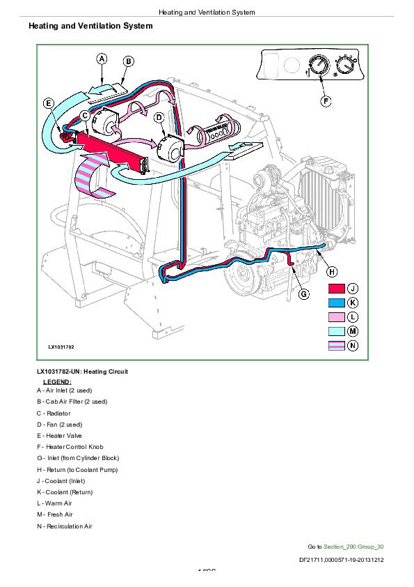
Heating and Ventilation System................1566
Group 50: Diagnostic Tests and Adjustments................1525
Safety in the Workplace................1569
Handling Refrigerant................1570
Safety Equipment................1571
In the Event of an Emergency................1572
Storage of Refrigerant Containers................1573
Refrigerant R134a................1574
Important................1575
Special Tools................1576
Installing Air Conditioning Test Equipment................1577
Air Conditioning System Pressure Test................1578
Air Conditioning System Static Pressure Test................1587
Temperature Drop Test................1592
Section 299: Information on Cab Components................1598
Group 40: Cab Components................1598
Air Conditioning Compressor................1600
A/C Condenser................1601
Air Conditioning High-Low Pressure Switch................1602
Air Conditioning Thermostat................1603
Air Conditioning Evaporator................1604
Air Conditioning Expansion Valve................1605
Air Conditioning Receiver-Dryer................1606
Air Conditioning On/Off Switch................1607
Air Conditioning Temperature Control Knob................1608
Heater Control Knob................1609
Cab Fan Speed Control Selector................1610
John Deere Tractors 5055E, 5065E, 5075E, 5078E, 5085E, 5090E Diagnosis and Tests Service Technical Manual (TM801619)


