John Deere Tractors 5050E, 5055E, 5065E, 5075E Diagnostics and Repair Service Manual (TM900319)
Catalog:
Model:
Complete All Inclusive Technical Manual with electrical wiring diagrams for John Deere Tractors 5050E, 5055E, 5065E, 5075E, with all the shop information to maintain, diagnose, repair, and service like professional mechanics (Diagnosis, Operation, Tests, Repair, Service, Troubleshooting).
John Deere 5050E, 5055E, 5065E, 5075E workshop diagnosis repair technical manual includes:
* Numbered table of contents easy to use so that you can find the information you need fast.
* Detailed sub-steps expand on repair procedure information
* Numbered instructions guide you through every repair procedure step by step.
* Troubleshooting and electrical service procedures are combined with detailed wiring diagrams for ease of use.
* Notes, cautions and warnings throughout each chapter pinpoint critical information.
* Bold figure number help you quickly match illustrations with instructions.
* Detailed illustrations, drawings and photos guide you through every procedure.
* Enlarged inset helps you identify and examine parts in detail.
TM900319 - John Deere 5050E, 5055E, 5065E and 5075E Tractors Technical Manual.pdf
Total Pages: 1,531 pages
File Format: PDF (PC/Mac/Android/Kindle/iPhone/iPad; bookmarked, ToC, Searchable, Printable)
Language: English
MAIN SECTIONS
Foreword
General Information
Safety
General Specifications
Fuel and Lubricants
Serial Number Locations
Features and Accessories
Engine Repair
Engine
Cylinder Head and Valves
Cylinder Block, Liners, Pistons and Rods
Crankshaft, Main Bearings and Flywheel
Camshaft and Timing Gear Train
Lubrication System
Cooling System
Fuel and Air Intake System Repair
Fuel System
Air Intake and Exhaust System
Speed Control Linkage
Electrical Repair
Battery, Starter and Alternator
Electrical System Components
Wiring Harness
Power Train Repair
Clutch Housing
Clutch Assembly
Transmission
Rear PTO Drive Shaft
Differential
Final Drives
Mechanical Front Wheel Drive – If Equipped
Steering and Brake Repair
Steering Repair
Brake Repair
Hydraulic Repair
Hydraulic Pump and Filter
JD Rockshaft
Selective Control Valve (SCV)
Miscellaneous Repair
Front Axle
Wheels
3-Point Hitch
Hood
Ballast
Operator Station Repair
Seat and Support
Right Console
Roll-Gard™
Center Console
Operator Station
Fenders
Operational Checkout Procedures
Operational Checkout Procedures
Engine Operation, Tests and Adjustments
Component Location
Theory of Operation
Diagnosis, Tests and Adjustments
Fuel/Air Operation, Tests and Adjustments
Component Location
Theory of Operation
Diagnosis, Tests and Adjustments
Electrical System Operation, Tests and Adjustments
Component Location
Theory of Operation
Diagnosis, Tests and Adjustments
Wiring Schematics
Component Information-Connectors
Power Train Operation, Tests and Adjustments
Component Location
Theory of Operation
Diagnosis, Tests and Adjustments
Steering and Brake Operation, Tests & Adjustments
Component Location
Theory of Operation
Diagnosis, Tests and Adjustments
Hydraulic System Operation, Tests and Adjustments
Component Location
Theory of Operation
Diagnosis
Hydraulic Tests-With SCV
Hydraulic Tests-With Mid-Mount Control Valve
Hydraulic Tests-Whole System
Adjustments-Hitch
Hydraulic Schematics
TABLE OF CONTENTS
Section 10: General Information................1550
Group 05: Safety................31
Recognize Safety Information................35
Understand Signal Words................36
Follow Safety Instructions................37
Prepare for Emergencies................38
Wear Protective Clothing................39
Protect Against Noise................40
Handle Fuel Safely—Avoid Fires................41
Fire Prevention................42
Use Foldable ROPS and Seat Belt Properly................43
Stay Clear of Rotating Drivelines................44
Use Steps and Handholds Correctly................46
Read Operator Manuals for ISOBUS Implements................47
Use Seat Belt Properly................48
Vibration................49
Operating the Tractor Safely................50
Avoid Backover Accidents................52
Limited Use in Forestry Operation................53
Operating the Loader Tractor Safely................54
Keep Riders Off Machine................55
Passenger Seat................56
Use Safety Lights and Devices................57
Towing Trailers/Implements Safely (Mass)................58
Use Caution On Slopes and Uneven Terrain................59
Freeing a Mired Machine................60
Avoid Contact with Agricultural Chemicals................61
Handle Agricultural Chemicals Safely................62
Handling Batteries Safely................64
Avoid Heating Near Pressurized Fluid Lines................66
Remove Paint Before Welding or Heating................67
Handle Electronic Components and Brackets Safely................68
Practice Safe Maintenance................69
Avoid Hot Exhaust................70
Clean Exhaust Filter Safely................71
Work In Ventilated Area................74
Support Machine Properly................75
Prevent Machine Runaway................76
Park Machine Safely................77
Transport Tractor Safely................78
Service Cooling System Safely................79
Service Accumulator Systems Safely................80
Service Tires Safely................81
Service Front-Wheel Drive Tractor Safely................82
Tightening Wheel Retaining Bolts/Nuts................83
Avoid High-Pressure Fluids................84
Do Not Open High-Pressure Fuel System................85
Store Attachments Safely................86
Dispose of Waste Properly................87
Group 10: General Specifications................1018
Machine Specifications................1018
Ground Speed Estimates................94
Service Recommendations for O-Ring Boss Fittings................98
Service Recommendations for Flat Face O-Ring Seal Fittings................100
Metric Bolt and Screw Torque Values................102
Unified Inch Bolt and Screw Torque Values................104
Group 20: Fuel and Lubricants................32
Diesel Fuel................108
Fuel Storage................110
Do Not Use Galvanized Containers................111
Fill Fuel Tank................112
Diesel Engine Oil................113
Heavy Duty Diesel Engine Coolant................115
Transmission and Hydraulic Oil................116
Grease (Specific Application)................117
Grease................118
Lubricant Storage................119
Group 25: Serial Number Locations................33
Serial Numbers................121
Product Identification Number Location................122
Engine Serial Number Location................123
Fuel Injection Pump Serial Number Location................124
Alternator Serial Number Location................125
Power Steering Valve Serial Number Location................126
Transmission Serial Number Location................127
Front Axle Serial Number Location- 2WD................128
Front Axle Serial Number Location—MFWD................129
Record ROPS Serial Number................130
Group 30: Features and Accessories................132
Features and Accessories................132
Standard Features................133
Factory Installed Optional Kits................136
Field Installed Optional Kits and Accessories................137
Section 20: Engine Repair................138
Group 05: Engine................138
Service Equipment and Tools................761
Specifications................1018
John Deere Engine Repair................147
Remove Engine................148
Install Engine................156
Engine Disassembly Sequence................163
Sealant Application Guidelines................165
Engine Re-Assembly Sequence................166
Engine Break-In Guidelines................168
Perform Engine Break-In................169
Diesel Engine Break-In Oil................170
Group 10: Cylinder Head and Valves................138
Special or Essential Tools................1019
Specifications................1018
Torques for Hardware................383
Cylinder Head - Exploded View................232
Check Valve Lift................183
Remove Cylinder Head................184
Clean Injection Nozzle Bores................187
Valve Actuating Parts................188
Remove Valves and Valve Springs................189
Checking Cylinder Head Flatness................190
Clean Valve Guides................191
Measure Valve Guides................192
Knurl Valve Guides................194
Clean and Inspect Valve Seats................195
Lapping Valve Seats................196
Check Valve Recess................197
Remove Valve Seat Inserts................198
Valve Seat Insert Installation................200
Check Valves................201
Grind Valves................202
Check Valve Spring Compression................203
Inspect Valve Rotators................204
Install Valves................205
Install Cylinder Head................207
Torque Turn Tightening Method................209
Disassembling and Checking Rocker Arm Shaft................211
Reassembling Rocker Arm Shaft................213
Install Rocker Arm Assembly................214
Valve Clearance................215
Valve Adjustment Sequence................216
Install Rocker Arm Cover................218
Final Work................219
Group 15: Cylinder Block, Liners, Pistons and Rods................139
Special or Essential Tools................1019
Specifications................1018
Torques for Hardware................383
Exploded View................232
Connecting Rods - General Information................1550
Remove Pistons and Connecting Rods................235
Measure Cylinder Liner Bore................237
Remove Cylinder Liners................238
Cylinder Liner Deglazing................239
Cylinder Block Cleaning................240
Check Piston Cooling Jets................241
Cam Follower Bore Measure................242
Measure Camshaft Bore................243
Remove Camshaft Bushing................244
Install Camshaft Bushing................245
Measure Crankshaft Bore................246
Replace Crankshaft Bearing Caps................247
Cylinder Block Top Desk Flatness................248
Measure Cylinder Liner Protrusion................249
Liner Packing Installation................251
Liner O-Ring Installation................252
Install Cylinder Liners................253
Measure Connecting Rod Bearing................254
Rod Bearing Clearance................256
Measure Connecting Rod Bushing................257
Replace Connecting Rod Bushing (3029D)................258
Replace Connecting Rod Bushing (3029T)................259
Measure Piston Pin................262
Clean and Inspect Pistons................263
Measure Piston Pin Bore................264
Piston Top Ring Groove................265
Second and Third Piston Ring Grooves................266
Piston Head and Skirt Checking................267
Install Piston Rings................268
Piston Rings Staggering................270
Piston/Liner Set Information................271
Assemble Piston and Connecting Rod................272
Install Piston and Connecting Rod................274
Measure Piston Protrusion................278
Complete Final Assembly................280
Group 20: Crankshaft, Main Bearings and Flywheel................140
Special or Essential Tools................1019
Specifications................1018
Torques For Hardware................416
Remove Crankshaft Pulley................289
Install Crankshaft Pulley................290
Flywheel Removal................291
Flywheel Ring Gear Replacement................292
Install Ball Bearing................293
Install Flywheel................294
Remove Crankshaft Rear Oil Seal................295
Flywheel Housing Replacement................298
Install Oil Seal/Wear Sleeve................300
Crankshaft End Play Measure................301
Remove Crankshaft................303
Crankshaft Inspection................304
Check Crankshaft Journal Diameter................305
Determine Crankshaft Main Bearing Clearance Using PLASTIGAGE PLASTIGAGE is a trademark of DANA Corp.................141
Regrind Crankshaft................308
Crankshaft Regrinding Guidelines................309
Micro-Finishing Specifications................1018
Replace Crankshaft Gear................311
Install Main Bearing Inserts................313
Install 2-Piece Thrust Bearing................314
Crankshaft Installation................315
Group 25: Camshaft and Timing Gear Train................141
Special or Essential Tools................1019
Specifications................1018
Torques for Hardware................383
Remove Crankshaft Front Oil Seal................324
Remove Timing Gear Cover................325
Measure Timing Gear Backlash................326
Camshaft End Play Measure................327
Remove Camshaft................328
Measure Camshaft Journal................329
Measure Height of Cam Lobe................330
Replace Camshaft Gear................331
Install Camshaft................332
Check Cam Follower................333
Idler Gear End Play Measure................334
Remove Front Plate................335
Idler Gear Bushing and Shaft Measure................337
Idler Gear Bushing Replacement................339
Remove Idler Shaft................340
Install Idler Shaft Spring Pin................341
Install Idler Shafts................342
Install Front Plate................343
Install Upper Timing Gear Train................345
Install Lower Timing Gear Train................347
Install Oil Deflector................348
Timing Gear Cover Identification................349
Install Timing Gear Cover................350
Install Crankshaft Front Oil Seal................352
Install Wear Ring................353
Install Auxiliary Equipment................354
Group 30: Lubrication System................142
Special or Essential Tools................1019
Specifications................1018
Torques for Hardware................383
Oil Cooler Identification................359
Remove Oil Cooler................360
Replace Oil Cooler Nipple................361
Install Oil Cooler................362
Replace Oil Cooler/Filter Bracket on Engine with Auxiliary Drive................363
Remove Oil Pressure Regulating Valve................365
Replace Oil Pressure Regulating Valve Seat................366
Install Oil Pressure Regulating Valve................367
Replace Oil Dipstick Guide................368
Replace Oil By-Pass Valve................369
Replace Oil Pump Strainer................370
Remove Oil Pump................371
Oil Pump Gear Axial Clearance................372
Oil Pump Gear Radial Clearance................373
Oil Pump Specifications................1018
Oil Pump Installation................375
Install Oil Pan................378
Group 35: Cooling System................142
Special or Essential Tools................1019
Specifications................1018
Torques for Hardware................383
Remove and Inspect Radiator................384
Water Pump — Exploded View................390
Remove Water Pump................391
Disassemble Water Pump................392
Assemble Water Pump................394
Install Water Pump................397
Inspect Thermostat................398
Cooling System Deaeration................400
Check Fan/Alternator Belt Tension................401
Install Radiator................403
Replace Thermostat................407
Section 30: Fuel and Air Intake System Repair................410
Group 05: Fuel System................410
Special or Essential Tools................1019
Self-Manufactured Tool Template For Front Plate Replacement................415
Torques For Hardware................416
Injection Pump, Nozzle and Governor Repair—Use CTM................417
Remove, Inspect and Install Fuel Tank................418
Replace Fuel Filter................422
Remove and Install Fuel Filter/Primer Pump Assembly................423
Remove Fuel Injection Nozzle................424
Clean Fuel Injection Nozzle................426
Fuel Injection Nozzle Disassembly................427
Install Fuel Injection Nozzle................428
Group 10: Air Intake and Exhaust System................410
Remove, Inspect, and Install Air Cleaner Elements................435
Check Air Inlet Pipe................439
Remove Turbocharger................443
Exhaust Manifold Inspection................445
Turbocharger Cut-Away View (Borge Warner)––If Equipped................447
Check Radial Clearance––If Equipped................449
Check Axial Clearance––If Equipped................450
Repair Turbocharger––If Equipped................451
Prelube Turbocharger––If Equipped................452
Install Turbocharger––If Equipped................453
Turbocharger Break-In––If Equipped................456
Recommendations for Turbocharger Use––If Equipped................457
Group 15: Speed Control Linkage................410
Inspect and Repair Speed Control Linkage................460
Section 40: Electrical Repair................462
Group 05: Battery, Starter and Alternator................462
Starter Repair—Use CTM................465
Remove and Install Battery................466
Remove and Install Starter................468
Alternator/Regulator Repair—Use CTM................470
Replace Alternator/Regulator................471
Group 10: Electrical System Components................462
Service Equipment and Tools................761
Other Material................803
Replace Air Filter Restriction Sensor................477
Replace Coolant Temperature Sensor................478
Replace Engine Speed Sensor................479
Replace Engine Oil Pressure Sensor................480
Replace Key Switch................482
Replace Light Switch................484
Replace Beacon Lamp Switch................486
Replace Turn Signal Switch................487
Replace Instrument Panel................489
Replace Rear PTO Switch................492
Replace Neutral Start Switch................494
Replace Differential Lock Switch................495
Replace MFWD Switch................497
Replace 7 Pin Connector................498
Replace Brake Switch................500
Replace Park Brake Switch................502
Replace Horn................504
Replace Fuel Level Sender................505
Replace Rotating Beacon Lamp................507
Group 15: Wiring Harness................462
Special or Essential Tools................1019
Service Parts Kits................787
Remove Connector Body from Blade Terminals................512
Replace WEATHER PACK WEATHER PACK is a trademark of Packard Electric. Connector................463
Install WEATHER PACK WEATHER PACK is a trademark of Packard Electric. Contact................463
Replace Battery Positive Cable................517
Replace Hood Wiring Harness................518
Replace Beacon Lamp Wiring Harness................520
Replace Engine Wiring Harness................522
Replace Console Wiring Harness................524
Replace Rear Wiring Harness................526
Replace 7 Pin Connector Wiring Harness................529
Section 50: Power Train Repair................530
Group 05: Clutch Housing................530
Service Equipment and Tools................761
Other Material................803
Specifications................1018
Separate Engine from Clutch Housing................537
Install Engine to Clutch Housing................543
Replace Clutch Housing Seal................549
Inspect and Repair Clutch Pedal and Linkage................551
Group 10: Clutch Assembly................530
Essential Tools................1019
Service Equipment and Tools................761
Other Material................803
Specifications................1018
Remove and Install Clutch Assembly................560
Disassemble and Inspect Clutch Assembly................563
Assemble Clutch Assembly................571
Traction Clutch Finger Adjustment................577
PTO Clutch Finger Adjustment................579
Remove and Inspect Clutch Release Mechanism and Shafts................581
Install Clutch Release Mechanism and Shafts................585
Group 15: Transmission................530
Specifications................1018
Separate Clutch Housing from Transmission................590
Install Clutch Housing to Transmission................593
Inspect and Repair Gear Shift Lever................596
Inspect and Repair Range Shift Lever................598
Remove Transmission................600
Disassemble and Inspect Transmission — SyncShuttle™................605
Assemble Transmission — SyncShuttle™................612
Install Transmission................619
Disassemble, Inspect and Assemble Gear Shift Shaft Assemblies................623
Disassemble, Inspect, and Assemble Transmission Top Shaft—SyncShuttle™ Transmission................625
Disassemble, Inspect, and Assemble Range Reduction Shaft................628
Disassemble, Inspect and Assemble Driven Shaft................630
Remove, Inspect, and Install Range Gears................632
Remove, Inspect, and Install Reverse Idler Shaft................634
Inspect and Repair Park Brake Lever................636
Remove, Inspect and Repair Park Brake................638
Group 20: Rear PTO Drive Shaft................531
Other Material................803
Specifications................1018
Remove, Inspect and Install Rear PTO Lever and Linkage................643
Remove and Install Standard Rear PTO Drive Shaft Assembly................645
Disassemble, Inspect and Assemble Standard Rear PTO Drive Shaft Assembly................647
Remove, Inspect and Install 540/540E Shift Lever and Linkage................650
Remove and Install 540/540E Rear PTO Drive Shaft Assembly – If Equipped................652
Disassemble, Inspect and Assemble Rear 540/540E PTO Drive Shaft Assembly – If Equipped................654
Group 25: Differential................531
Essential Tools................1019
Service Equipment and Tools................761
Other Material................803
Specifications................1018
Service Parts Kits................787
Remove and Install Differential Assembly................664
Disassemble, Inspect, and Assemble Differential Assembly................666
Remove and Inspect Differential Drive Shaft................668
Install Differential Drive Shaft................672
Remove, Inspect, and Install Differential Lock Assembly................677
Differential Cone Point Adjustment................679
Differential Backlash Adjustment................681
Group 30: Final Drives................531
Service Equipment and Tools................761
Other Material................803
Specifications................1018
Remove and Install Final Drive Assembly................687
Remove and Inspect Planetary Drive Assembly................689
Install Planetary Drive Assembly................692
Remove, Inspect, and Install Axle Shaft Assembly................695
Group 35: Mechanical Front Wheel Drive – If Equipped................532
Service Equipment and Tools................761
Essential Tools................1019
Other Material................803
Specifications................1018
MFWD Axle Repair................707
Inspect and Repair MFWD Lever and Linkage................708
Remove and Install MFWD Drop Gearbox................709
Disassemble and Inspect MFWD Drop Gear box................711
MFWD Drop Gearbox Cross Section................714
Assemble MFWD Drop Gearbox................716
Remove, Inspect and Install MFWD Drive Shaft................722
Remove and Install MFWD Axle Housing Assembly................723
Remove, Inspect and Install MFWD Axle Supports (Without Paddy Seal)................725
Section 60: Steering and Brake Repair................727
Group 05: Steering Repair................727
Other Material................803
Specification................936
Service Parts Kits................787
Remove and Install Steering Wheel................732
Remove and Install Steering Column and Valve................736
Disassemble and Inspect Steering Valve - Eaton................741
Assemble Steering Valve - Eaton................746
Remove and Install Steering Cylinder—2WD Axle................752
Disassemble, Inspect and Assemble Steering Cylinder—2WD Axle................754
Remove, Inspect and Install Tie Rod Assembly—2WD................756
Inspect and Replace Steering Hydraulic Lines................758
Group 10: Brake Repair................727
Service Equipment and Tools................761
Other Material................803
Specification................936
Remove and Install Brake Valve................764
Disassemble and Inspect Brake Pedals and Valve................766
Brake Valve Cross Section................769
Assemble Brake Valve................771
Remove and Inspect Brakes................774
Install Brakes................777
Inspect and Replace Brake Hydraulic Lines................780
Section 70: Hydraulic Repair................782
Group 05: Hydraulic Pump and Filter................782
Essential Tools................1019
Specification................936
Service Parts Kits................787
Remove, Inspect, and Install Hydraulic Oil Pick-Up Screen................788
Remove and Install Hydraulic Pump................789
Remove Hydraulic Pump External Components................791
Disassemble and Inspect Hydraulic Pump................792
Assemble Hydraulic Pump................795
Install Hydraulic Pump External Components................797
Remove and Install Hydraulic Oil Filter/Manifold................799
Inspect and Replace Hydraulic Supply and Suction/Return Lines................800
Group 10: JD Rockshaft................782
Other Material................803
Specification................936
Inspect and Repair Rockshaft Control Lever Assembly................805
Inspect and Repair Rockshaft Control Linkage................810
Inspect and Repair Draft Sensing Support Assembly................814
Replace Main Relief Valve................816
Replace Rockshaft Surge Relief Valve................818
Remove, Inspect, and Install Rate-of-Drop Valve................820
Replace Rockshaft Control Valve................823
Remove and Install Rockshaft Case................827
Remove, Inspect, and Install Rockshaft Lift Arms................830
Remove, Inspect, and Install Rockshaft Piston and Cylinder................832
Group 15: Selective Control Valve (SCV)................782
Specification................936
Inspect and Repair SCV Lever and Linkage................837
Remove and Install EATON Selective Control Valve................839
Remove and Install Rear Coupler Bracket................843
Remove and Install SCV Oil Lines................846
Disassemble, Inspect and Assemble Dual Mid-Mount Selective Control Valve (SCV)................847
Section 80: Miscellaneous Repair................853
Group 05: Front Axle................853
Specification................936
Remove and Install Front Axle—2WD................856
Remove and Install Front Axle — MFWD................859
Inspect and Replace Pivot Pin and Bushings—2WD Axle................863
Remove and Install Spindle Assembly—2WD................864
Inspect and Replace Spindle Shaft Bushings—2WD Axle................866
Group 10: Wheels................853
Specifications................1018
Remove and Install Front or Rear Wheels................869
Inspect and Replace Front Wheel Bearings................870
Tighten Bolts—Rear Axle (M-20 Bolt)................872
Tighten Nuts—Front Axle (MFWD)................873
Tighten Cap Screws—Front Axle (2WD)................874
Group 15: 3-Point Hitch................853
Specification................936
Inspect and Repair Fixed Draft Links................877
Inspect and Repair Lift Link................878
Inspect and Repair Center Link................880
Remove and Install Wagon Hitch and Support................881
Group 20: Hood................853
Specification................936
Remove and Install Hood................884
Group 25: Ballast................853
Specifications................1018
Remove and Install Front Ballast................889
Remove and Install Rear Ballast—For 5055E, 5065E and 5075E Turkey Tractors Only................893
Section 90: Operator Station Repair................895
Group 05: Seat and Support................895
Specifications................1018
Remove and Install Seat and Support................898
Group 06: Right Console................895
Remove and Install Right-Side Control Console................903
Group 10: Roll-GardRoll-Gard is a trademark of Deere & Company.................895
Specification................936
Remove ROLL-GARD™................909
Install ROLL-GARD™................915
Group 15: Center Console................895
Specification................936
Remove Center Console Assembly................923
Install Center Console Assembly................929
Group 20: Operator Station................895
Specification................936
Remove Isolated Open Operator Station................937
Install Isolated Open Operator Station................948
Remove and Install Left and Right Side Steps................960
Group 25: Fenders................895
Remove and Install Fenders................965
Section 210: Operational Checkout Procedures................968
Group 10: Operational Checkout Procedures................968
Operational Checkout Procedure Information................970
Engine Oil Level and Condition Check................971
Coolant Level and Condition Check................973
Transmission and Hydraulic Oil Check................974
Fan and Belt Check................975
Fuel System Check................976
Air Intake System Check................977
Electrical System Check................979
Hydraulic System Check................981
Indicator Light Check................982
Engine Start Check................984
Transmission Neutral Start Check................986
Engine Fast and Slow Idle Operation................987
Power Steering Check................988
Differential Lock Check................989
Clutch Check................990
Transmission Shift Check................991
Range-Shift Lever Check................992
Brake Check................994
Park Brake Check................995
Hitch Check................996
Selective Control Valve Check................998
Miscellaneous Checks................1000
Section 220: Engine Operation, Tests and Adjustments................1001
Group 05: Component Location................1001
Component Location Information................1476
Engine External Components—Left-Hand Side................1005
Engine External Components—Right-Hand Side................1007
Group 10: Theory of Operation................1001
Theory of Operation Information................1480
Engine Lubrication System Operation................1011
Engine Cooling System Operation................1015
Group 15: Diagnosis, Tests and Adjustments................1001
Specifications................1018
Essential Tools................1019
Diagnostic Information................1522
Engine Turns Over But Will Not Start or Starts Hard................1021
Engine Runs Irregularly or Stalls Frequently................1022
Engine Runs Rough................1023
Engine Low Power................1024
Engine Smokes—Black or Gray................1026
Engine Smokes Excessively—White................1027
Engine Uses Excess Fuel................1028
Engine Has Excess Noise or Vibration................1029
Engine Uses Excess Oil or Smokes Blue................1030
Engine Has Low Oil Pressure................1031
Engine Coolant Operating Temperature Incorrect................1032
Oil In Coolant or Coolant in Oil................1034
Radiator Bubble Test................1035
Cooling System Test................1038
Radiator Cap Pressure Test................1039
Engine Oil Pressure Test................1040
Cylinder Compression Pressure Test................1042
Fuel Shutoff Solenoid Check................1044
Throttle Lever Adjustment................1045
Rotary Fuel Injection Pump Timing Adjustment................1046
Rotary Fuel Injection Pump Slow Idle Adjustment................1047
Rotary Fuel Injection Pump Fast Idle Adjustment................1049
Valve Clearance Adjustment................1051
Fan/Alternator Drive Belt Adjustment................1053
Bleeding Fuel System – Rotary Pump................1055
Section 230: Fuel/Air Operation, Tests and Adjustments................1058
Group 05: Component Location................1058
Component Location Information................1476
Fuel System Components................1061
Air System Components................1063
Group 10: Theory of Operation................1058
Theory of Operation Information................1480
Fuel System Operation................1068
Fuel Filter Operation................1071
Fuel Injection Nozzle Operation................1073
Air System Operation................1076
Turbocharger Operation––If Equipped................1080
Check Turbocharger Boost Pressure––If Equipped................1081
Diagnosing Turbocharger Malfunctions––If Equipped................1082
Viscous Fan Clutch Operation................1083
Stanadyne Rotary Fuel Injection Pump Operation................1085
Cold Weather Starting Aid Operation................1087
Group 15: Diagnosis, Tests and Adjustments................1058
Diagnostic Information................1522
Fuel/Air Diagnosis, Tests and Adjustments................1091
Section 240: Electrical System Operation, Tests and Adjustments................1092
Group 05: Component Location................1092
Component Location Information................1476
Engine Electrical Components—Right-Hand Side................1099
Engine Electrical Components—Left-Hand Side................1100
Dashboard and Center Control Console Electrical Components................1101
Tractor Electrical Components................1103
Group 10: Theory of Operation................1092
Theory of Operation Information................1480
Fuse Block and Fuses................1107
Relays................1109
Starting System Operation—Normal................1110
Starting System Operation—Bypass Attempt................1112
Charging System Operation................1114
Turn Signal and Warning Light Operation................1116
Parking Light Operation................1119
Headlights and Instrument Lights Operation................1121
Tachometer/Hour Meter Operation................1123
Fuel Gauge Operation................1125
Temperature Gauge Operation................1127
PTO Indicator Operation................1129
Air Filter Restriction Indicator Operation................1131
7-Pin Trailer Outlet Connector Operation................1092
Horn Operation................1135
Flood Light Operation................1137
Beacon Light Operation................1139
MFWD Indicator and Differential Lock Indicator Operation................1141
Fuel Pump Operation................1143
Brake Switch Operation................1145
Engine Oil Pressure Indicator Operation................1147
Park Brake Indicator Operation................1149
Manifold Heater Operation................1151
Group 15: Diagnosis, Tests and Adjustments................1093
Diagnostic Information................1522
Starting System Test Points................1155
Charging System Test Points................1158
Turn Signals Test Points................1161
Warning Light Test Points................1165
Flood Light Test Points................1167
Beacon Light Test Points................1170
Headlight and Instrument Light Test Points................1173
Tachometer/Hourmeter Test Points................1176
Fuel Gauge Test Points................1178
PTO Indicator Test Points................1181
Park Brake Indicator Test Points................1184
Temperature Gauge Test Points................1187
Engine Oil Pressure Indicator Test Points................1190
Air Filter Restriction Indicator Test Points................1193
MFWD and Differential Lock Indicator Test Points................1196
Manifold Heater Test Points................1199
Brake Switch Test Points................1202
Fuel Pump Test Points................1204
Horn Test Points................1206
Accessory Relay and Trailer Connector Test Points................1208
Battery Voltage and Specific Gravity Tests................1211
Charge Battery................1213
Battery Load Test................1215
Starter Amp Draw/RPM Test................1217
Starter No-Load amp Draw/RPM Test................1219
Alternator/Regulator Test................1221
Starter Solenoid Test................1223
Starter Relay Test................1224
Key Switch Test................1226
Plug-In Relay Test................1228
Mini Plug-In Relay................1230
Diode Pack Test................1232
Fuse Test................1234
Neutral Start Switch Test................1235
PTO Switch Test................1237
Park Brake Switch Test................1238
Light Switch Test................1239
Turn Signal Switch Test................1241
Fuel Shut-Off Solenoid Test................1243
Group 20: Wiring Schematics................1094
Schematic Information................1245
Component Identification Table................1246
Quick Reference Table................1248
Reference Tables................1250
SE01—Starting Motor, Charging Circuit, Jump Start and Back EMF Protection................1252
SE01A—Starting Aid (Heater Manifold and Fuel Pump)................1253
SE02—Instrument Gauges, Sensors and Switches................1254
SE03—Turn Signals and Hazard Switch................1255
SE04—Light Switch, Left and Right Headlights, and Beacon Light................1256
SE05—Horn................1257
SE06—Trailer Connector................1259
Group 25: Component Information—Connectors................1094
Component Location—Connectors (Summary of Information)................1262
X1—6-Pin Connector for Electronic Flasher................1263
X2 and X3—12-Pin Connectors for Front to Console Wiring Harness................1264
X4 and X5—3-Pin Connectors for Console to Hood Wiring Harness................1266
X6—2-Pin Connector for Trailer Connector................1268
X7—1-Pin Connector for Junction Box................1269
X8—6-Pin Connector for Trailer Connector................1270
X9 and X10—12-Pin Connectors for Console to Rear Wiring Harness................1271
X11 and X12—6-Pin Connectors for Console to Rear Wiring Harness................1273
X13—60-Pin Connector for Fuse Box................1275
XA01—16-Pin Connector for Instrument Cluster................1278
XA02—6-Pin Connector for Instrument Cluster................1280
XB02—2-Pin Connector for Engine Speed Sensor................1281
XB03—2-Pin Connector for Fuel Level Sensor................1282
XB04—1-Pin Connector for Coolant Temperature Sensor................1283
XB05—1-Pin Connector for Engine Oil Pressure Switch................1284
XB06—2-Pin Connector for Air Filter Restriction Sensor................1285
XE01/1—1-Pin Connector for License Plate................1286
XE01/2—1-Pin Connector for License Plate................1287
XE02—2-Pin Connector for Left Front Turn Signal................1288
XE03—3-Pin Connector for LH Rear Fender Light................1289
XE04—2-Pin Connector for Right Front Turn Signal................1290
XS04—2-Pin Connector for Park Brake Switch................1291
XY01—1-Pin Connector for Fuel Shutoff Solenoid................1292
XS02—6-Pin Connector for PTO Switch................1293
XE14—2-Pin Connector for Beacon Light Switch................1294
XK03/1—1-Pin Connector for Manifold Heater Relay................1295
XK03/2—1-Pin Connector for Manifold Heater Relay................1296
XM01/1—1-Pin Connector for Starter Motor Solenoid................1297
XM01/2—1-Pin Connector for Starter Motor Solenoid................1298
XG02/1—2-Pin Connector for Alternator................1299
XG02/2—1-Pin Connector for Alternator................1300
XH01/1—1-Pin Connector for Horn................1301
XH01/2—1-Pin Connector for Horn................1302
XE05—3-Pin Connector for RH Rear Fender Light................1303
XE12—3 Pin Connector for Right Headlight................1304
XE13—3-Pin Connector for Left Headlight................1305
XE15—2-Pin Connector for Flood Light................1306
XS03—2-Pin Connector for Neutral Start Switch................1307
XY02/1—1-Pin Connector for Differential Lock Switch................1308
XY02/2—1-Pin Connector for Differential Lock Switch................1309
XY03—2-Pin Connector for Fuel Pump................1310
XS06—6-Pin Connector for Hazard Switch................1311
XS10—6-Pin Connector for Light Switch................1312
XS07—3-Pin Connector for Turn Signal Switch................1313
XS11/1—1-Pin Connector for Horn Switch................1314
XS11/2—1-Pin Connector for Horn Switch................1315
XS09—3 Pin Connector for Beacon Light Switch................1316
XS01—8-Pin Connector for Key Switch................1317
XS08/1—1-Pin Connector for Brake Switch................1318
XS08/2—1-Pin Connector for Brake Switch................1319
XK11/1—2-Pin Connector for Starter Relay................1320
XK11/2—1-Pin Connector for Starter Relay................1321
XK11/3—1-Pin Connector for Starter Relay................1322
XV01—9-Pin Connector for Diode Module................1323
XS05/1—1-Pin Connector for MFWD Switch................1324
XS05/2—1-Pin Connector for MFWD Switch................1325
XGND1—Ground (Left Front Turn Signal)................1326
XGND2—Ground (Left Rear Fender Light)................1327
XGND3—Ground (Front Wiring Harness)................1328
XGND4—Ground (Right Front Turn Signal)................1329
XGND5—Ground (Right Rear Fender Light)................1330
XGND6—Ground (Rear Wiring Harness)................1331
XGND7—Ground (Body Earthing)................1332
XGND8—Ground (Console Wiring Harness)................1333
Section 250: Power Train Operation, Tests and Adjustments................1334
Group 05: Component Location................1334
Component Location Information................1476
Power Train Components................1338
Clutch Components—Dual................1339
Transmission Components—SyncShuttle™................1341
Final Drive Components................1343
Park Brake Components................1344
Rear 540 PTO Components................1346
Rear 540/540E PTO Components––If Equipped................1347
Group 10: Theory of Operation................1334
Theory of Operation Information................1480
Clutch Operation—Dual Clutch................1350
Transmission Lubrication System................1358
SyncShuttle™ Transmission—Gear Shift Power Flow................1360
SyncShuttle™ Transmission Synchronizer Operation—Reverse and 2nd Gear (Disk-and-Plate Type Synchronizer)................1362
SyncShuttle™ Transmission Synchronizer Operation - 1st and 3rd Gear (Cone-Type Synchronizer)................1364
SyncShuttle™ Transmission—Range Shift Power Flow................1366
Mechanical Front Wheel Drive (MFWD) Operation (If Equipped)................1368
Rear 540 PTO Operation................1370
Rear 540/540E PTO Operation––If Equipped................1372
Differential Power Flow................1373
Differential Lock Operation................1375
Final Drive Operation................1377
Group 15: Diagnosis, Tests and Adjustments................1334
Diagnostic Information................1522
Isolate the Problem Area................1381
Traction Clutch Slips................1383
Traction Clutch Dragging................1384
Traction Clutch Does Not Engage................1385
Traction Clutch Grabs................1386
Traction Clutch Squeaks................1387
Traction Clutch Does Not Release................1388
Traction Clutch Chatters................1389
Traction Clutch Rattles................1390
Traction Clutch Engagement Is Noisy................1391
Excessive Vibration in Traction Clutch................1392
Clutch Pedal Does Not Return................1393
Clutch Pedal Loose................1394
Clutch Pedal Pulsates................1395
Jerky or Rough Transmission of Power................1396
Low Transmission Oil Level (Excessive Oil Leakage)................1397
Gears Clash, Shift Hard, or Will Not Engage................1398
Two Speeds Engage Together................1399
Transmission Will Not Stay in Gear................1400
Transmission Noisy................1401
PTO Noisy................1402
PTO Hard to Engage................1403
PTO Will Not Operate................1404
PTO Will Not Stay Engaged................1405
Excessive Differential Noise................1406
Differential Does Not Work................1407
No Differential Lock................1408
Differential Chatters................1409
Axle Noise................1410
Axle Shaft Will Not Turn................1411
Check and Adjust Clutch Pedal Free Play................1412
Adjust PTO Clutch Lever Linkage Adjustment................1413
Adjust 540E PTO Lever Linkage................1415
Section 260: Steering and Brake Operation, Tests Section 260: Steering and Brake Operation, Tests & Adjustments{pgNO}1417 Adjustments................1417
Group 05: Component Location................1417
Component Location Information................1476
Steering System Components................1421
Brake System Components................1422
Trailer Brake System Components................1424
Group 10: Theory of Operation................1417
Theory of Operation Information................1480
Steering System Operation................1427
Steering Valve Operation—Neutral and Manual Turning................1429
Steering Valve Operation—Power Turning................1431
Brake System Operation................1433
Brake Valve Operation................1435
Trailer Brake System Operation................1439
Trailer Brake Valve Operation................1441
Group 15: Diagnosis, Tests and Adjustments................1417
Diagnostic Information................1522
Isolate the Problem—Steering System................1449
Steering Sluggish or Loss of Steering................1450
Isolate the Problem—Brakes................1451
Excessive Brake Pedal Leak-Down................1452
Excessive Brake Chatter................1453
Trailer Brake Valve Operational Check................1454
Trailer Brake Valve Troubleshooting................1455
Steering Pump Flow Test................1457
Steering Valve Relief Test................1459
Steering Cylinder Leakage Test................1460
Steering Valve Leakage Test................1461
Check Toe-In—Two-Wheel Drive Tractor................1463
Adjust Toe-In (Two-Wheel Drive Tractor)................1464
Check Toe-In—MFWD Tractor................1465
Adjusting Toe-In—MFWD Tractor................1466
Brake Pedal Adjustment................1467
Bleed Brake System................1469
Park Brake Linkage Adjustment................1470
Section 270: Hydraulic System Operation, Tests and Adjustments................1472
Group 05: Component Location................1472
Component Location Information................1476
Hydraulic System Components................1477
Group 10: Theory of Operation................1472
Theory of Operation Information................1480
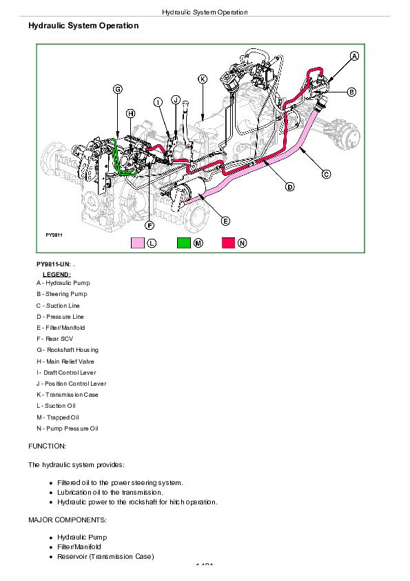
Hydraulic System Operation................1481
Hydraulic Filter Operation................1483
Hydraulic Pump Operation................1485
Hitch Valve Operation—Neutral Phase................1487
Hitch Valve Operation—Delivery Phase................1489
Hitch Valve Operation—Discharge Phase................1491
Hitch Rate-of-Drop Valve (Implement Lock) Operation................1493
JD Rockshaft Draft-Sensing Operation................1495
JD Rockshaft Surge Relief Valve Operation................1497
Hitch Main Relief Valve Operation................1499
Functioning of Position Control................1501
Functioning of Draft Control................1503
Combined Functioning of Position and Draft Control................1505
Hydraulics - Dual Mid-Mount SCV Extend and Retract Operation................1506
Hydraulics - Dual Mid-Mount SCV Float Operation................1508
Hydraulics - Dual Mid-Mount SCV Neutral Operation................1510
EATON Selective Control Valve—Neutral Position................1513
EATON Selective Control Valve—Retract Position................1515
EATON Selective Control Valve—Extend Position................1517
EATON Selective Control Valve—Float Position................1519
Group 15: Diagnosis................1472
Diagnostic Information................1522
Preliminary Hydraulic System Inspection................1523
Entire Hydraulic System Fails to Function/No Hydraulic Pump Output................1524
Insufficient Pump Delivery................1525
Hydraulic Functions Too Slow................1526
Excessive Pump Pressure................1527
Slow Hydraulic Pump Response................1528
Excessive Pump Noise During Operation................1529
Rockshaft Does Not Lift or Lifts Slowly................1530
Rockshaft Does Not Lower or Lowers Slowly................1531
Park Position Unstable, Rockshaft Drops after Engine Shut Down................1532
SCV Control Lever Does Not Return to Neutral Position................1533
SCV Does Not Return to Neutral Position-SCV With Detent Position................1534
SCV Does Not Remain In Detent Position-SCV With Detent Position................1535
Remote Cylinder Does Not Extend or Retract................1536
Remote Cylinder Settles Under Load................1537
Remote Cylinder Operates Too Fast or Too Slow................1538
Group 20: Hydraulic Tests—With SCV................1473
Hydraulic System Tests—With SCV................1541
Pump Flow Test—With SCV................1543
Main Relief Valve Test—With SCV................1545
SCV Leakage Test................1547
Group 25: Hydraulic Tests—With Mid-Mount Control Valve................1473
General Information................1550
Hydraulic System Tests—With Mid-Mount Control Valve................1551
Pump Flow Test—With Mid-Mount Control Valve................1553
Main Relief Valve Test—With Mid-Mount Control Valve................1555
Mid-Mount Control Valve Leakage Test................1557
Group 30: Hydraulic Tests—Whole System................1473
Hitch Leakage Test................1560
Rockshaft Lift Cycle Test................1562
Group 40: Adjustments—Hitch................1473
Rockshaft Lever Friction Adjustment................1565
Rockshaft Position-Sensing Feedback Linkage Adjustment................1566
Rockshaft Draft-Sensing Feedback Linkage Adjustment................1570
Rear SCV Lever Cable Adjustment................1572
Mid-Mount Control Valve Joystick Cable Adjustment................1573
Group 45: Hydraulic Schematics................1474
Hydraulic Circuit Symbols................1576
Hydraulic System—Standard Tractor with Second Rear SCV and Trailer Brake Valve................1578
Hydraulic System—Standard Tractor with Mid-Mount SCV................1580
John Deere Tractors 5050E, 5055E, 5065E, 5075E Diagnostics and Repair Service Manual (TM900319)


