John Deere 5045E, 5055E, 5065E and 5075E (FT4) Tractors (S.No. 748241— ) Repair Service Manual (TM902519)
Catalog:
Model:
Complete Repair Service Technical Manual for John Deere 5045E, 5055E, 5065E and 5075E (FT4) Tractors (S.No. 748241— ), with all the workshop information to maintain, repair, and rebuild like professional mechanics.
John Deere 5045E, 5055E, 5065E and 5075E (FT4) Tractors (S.No. 748241— ) workshop technical manual (repair) includes:
* Numbered table of contents easy to use so that you can find the information you need fast.
* Detailed sub-steps expand on repair procedure information
* Numbered instructions guide you through every repair procedure step by step.
* Notes, cautions and warnings throughout each chapter pinpoint critical information.
* Bold figure number help you quickly match illustrations with instructions.
* Detailed illustrations, drawings and photos guide you through every procedure.
* Enlarged inset helps you identify and examine parts in detail.
TM902519 English - John Deere 5045E, 5055E, 5065E and 5075E (FT4) Tractors (S.No. 748241— ) Repair Technical Manual.pdf
tm902528 French - Manuel technique de remise en état, tracteurs 5045E, 5055E, 5065E et 5075E (FT4) (n de série 748241 —).pdf
PRODUCT DETAILS:
Total Pages: 904 pages
File Format: PDF (bookmarked, ToC, Searchable, Printable)
Language: English
TABLE OF CONTENTS
Section 10: General Information................18
Group 05: Safety................18
Recognize Safety Information................22
Understand Signal Words................23
Follow Safety Instructions................24
Handle Fluids Safely—Avoid Fires................25
Prevent Battery Explosions................26
Prepare for Emergencies................27
Prevent Acid Burns................28
Service Cooling System Safely................30
Avoid High-Pressure Fluids................31
Park Machine Safely................32
Support Machine Properly................33
Wear Protective Clothing................34
Work in Clean Area................35
Service Machines Safely................36
Work In Ventilated Area................37
Illuminate Work Area Safely................38
Replace Safety Signs................39
Use Proper Lifting Equipment................40
Service Tires Safely................41
Avoid Harmful Asbestos Dust................42
Avoid Heating Near Pressurized Fluid Lines................43
Remove Paint Before Welding or Heating................44
Use Proper Tools................45
Dispose of Waste Properly................46
Live With Safety................47
Group 10: General Specifications (9x3 TSS Transmission)................18
Machine Specifications................915
Repair Specifications................915
Ground Speed Estimates — Sync Shuttle Transmission................57
Service Recommendations for O-Ring Boss Fittings................80
Service Recommendations for Flat Face O-Ring Seal Fittings................82
Metric Bolt and Cap Screw Torque Values................84
Unified Inch Bolt and Cap Screw Torque Values................85
Glossary of Terms................87
Group 11: General Specifications (12x12 PR Transmission)................19
Machine Specifications................915
Repair Specifications................915
Ground Speed Estimates —PowrReverser Transmission................79
Service Recommendations for O-Ring Boss Fittings................80
Service Recommendations for Flat Face O-Ring Seal Fittings................82
Metric Bolt and Cap Screw Torque Values................84
Unified Inch Bolt and Cap Screw Torque Values................85
Glossary of Terms................87
Group 15: Fuel and Lubricants................19
Diesel Fuel................93
Handling and Storing Diesel Fuel................95
Lubricity of Diesel Fuel................96
Testing Diesel Fuel................97
Biodiesel Fuel................98
Do Not Use Galvanized Containers................100
Fill Fuel Tank................101
Diesel Engine Break-In Oil — Non-Emissions Certified and Certified Tier 1, Tier 2, Tier 3, Stage I, Stage II, and Stage III................103
Diesel Engine Oil — Interim Tier 4, Final Tier 4, Stage IIIB, Stage IV, and Stage V................105
Oil Filters................107
Diesel Engine Coolant (engine with wet sleeve cylinder liners)................108
Operating in Warm Temperature Climates................110
Water Quality for Mixing with Coolant Concentrate................111
Testing Coolant Freeze Point................112
Transmission and Hydraulic Oil................114
Additional Information About Diesel Engine Coolants and John Deere LIQUID COOLANT CONDITIONER................115
Use Correct Transmission/Hydraulic Filter Element................117
Gear Oil................118
Multipurpose Extreme Pressure (EP) Grease................119
Mixing of Lubricants................120
Alternative and Synthetic Lubricants................121
Lubricant Storage................122
Group 20: Serial Number Locations................20
Serial Numbers................124
Product Identification Number................125
Record Engine Serial Number................126
Fuel Injection Pump Serial Number................127
Alternator Serial Number Location................128
Power Steering Valve Serial Number Location................129
Starter Serial Number Location................130
Transaxle Serial Number Location (12x12 PR Transmission)................131
Record Front Axle (2-WD) Serial Number................132
Record Mechanical Front Wheel Drive (MFWD) Serial Number................133
Group 25: Features and Accessories................135
Features and Accessories................135
Standard Features................136
Factory Installed Optional Equipment................138
Field Installed Optional Kits and Accessories................139
Section 20: Engine Repair................140
Group 05: Engine................140
Service Equipment and Tools................913
Specifications................915
John Deere Engine Repair—Use CTM................144
Remove Engine — Cab................145
Remove Engine — OOS................154
Install Engine — Cab................162
Install Engine — OOS................170
Remove and Install Rocker Arm Cover................177
Group 30: Cooling System................140
Special or Essential Tools................910
Specifications................915
Torques for Hardware................181
Remove and Inspect Radiator (OOS)................182
Remove and Inspect Radiator (Cab)................188
Water Pump — Exploded View................194
Cooling System Repair—Use CTM................195
Section 30: Fuel, Air Intake and Exhaust Systems................196
Group 05: Fuel System................196
Special or Essential Tools................910
Injection Pump, Nozzle and Governor Repair—Use CTM................205
Remove, Inspect and Install Fuel Tank (OOS)................206
Remove, Inspect and Install Fuel Tank (Cab)................209
Remove, Inspect and Install Fuel Cooler................213
Group 10: Air Intake System................196
Remove, Inspect, and Install Air Cleaner Elements................218
Remove, Inspect and Install Air Cleaner Assembly................221
Check Air Inlet Pipe with Turbocharger................223
Remove and Install Turbocharger................224
Turbocharger Repair................226
Group 15: Exhaust System................196
Other Material................914
Specifications................915
Service Exhaust System................230
Section 40: Electrical Repair................238
Group 05: Battery, Starter and Alternator................238
Starter Repair—Use CTM................242
Remove and Install Battery (OOS)................243
Remove and Install Battery (CAB)................246
Remove and Install Starter................249
Replace Alternator/Regulator................250
Group 10: Electrical System Components................238
Essential or Recommended Tools................684
Other Material................914
Specifications................915
Servicing Electronic Control Units................255
Keep Electronic Control Unit Connectors Clean................256
Repair Engine Electrical System Components—Use CTM................257
Replace Air Filter Restriction Sensor................258
Replace Coolant Temperature Sensor................259
Replace Engine Speed Sensor................260
Replace Engine Oil Pressure Sensor................261
Replace Key Switch (OOS)................262
Replace Key Switch (CAB)................264
Replace Light Switch (OOS)................265
Replace Light Switch (CAB)................267
Replace Turn Signal Switch (OOS)................269
Remove and Replace Turn Signal Switch (Cab)................271
Replace Wiper Control Switch................272
Remove and Install Wiper Motor................273
Remove and Install Instrument Panel................789
Remove and Replace Forward, Neutral, Reverse Lever (If Equipped)................278
Remove and Install Acceleration Potentiometer (Shuttle Control) (If Equipped)................280
Replace Horn Switch (If Equipped)................281
Replace Starter Relay................282
Replace Hand Throttle Position Sensor................284
Replace Foot Throttle Position Sensor................286
Replace Rear PTO ON/OFF Switch (OOS)................291
Replace Electro-Hydraulic Control (EHC) Unit—Cab................292
Replace Electro-Hydraulic Control (EHC) Unit—OOS................294
Replace Engine Control Unit (ECU) (2.9 L)................296
Replace Enable Proportional Solenoid Valve—PR Transmission................298
Replace Transmission Reverse Solenoid Valve—PR Transmission................300
Replace Transmission Forward Solenoid Valve—PR Transmission................301
Replace Clutch Pedal Position Sensor (PR Transmission)................302
Remove and Install Rear PTO Switch (TSS Transmission)—OOS................305
Remove and Install Rear PTO Switch (TSS Transmission)—Cab................307
Replace Neutral Start Switch................309
Replace Seat Switch (OOS)................310
Replace Seat Switch (Cab)................312
Replace Fuel Level Sender (OOS)................313
Replace Fuel Level Sender (Cab)................314
Group 15: Wiring Harness................239
Service Equipment and Tools................913
Essential Tools................910
Remove Connector Body from Blade Terminals................319
Replace WEATHER PACK WEATHER PACK is a trademark of Packard Electric. Connector................239
Install WEATHER PACK WEATHER PACK is a trademark of Packard Electric. Contact................239
Repair (Pull Type) METRI-PACK™ Connectors................324
Repair (Push Type) METRI-PACK™ Connectors................326
Exploded View—CINCH Flexbox Connectors................329
CINCH™ Flexbox Connectors................330
Repair DEUTSCH™ Connectors................334
Replace Positive Battery Cable (OOS)................338
Replace Positive Battery Cable (CAB)................339
Replace Engine Power Cable................340
Replace Hood Wiring Harness (OOS and CAB)................342
Replace Beacon Lamp Wiring Harness (If Equipped)................344
Replace Front Console Wiring Harness—OOS (9x3 TSS Transmission)................345
Replace Front Console Wiring Harness—OOS (12x12 PowrReverser™ Transmission)................348
Replace Front Console Wiring Harness—Cab (9x3 TSS Transmission)................351
Replace Front Console Wiring Harness—Cab (12x12 PowrReverser™ Transmission)................353
Replace Right-Hand Console Wiring Harness—OOS (12x12 PowrReverser™ Transmission)................355
Replace Transmission Harness—Cab (12x12 PowrReverser™ Transmission)................356
Replace Engine Harness................359
Replace Cab Power Harness................360
Replace Rear Wiring Harness—OOS (9x3 TSS Transmission)................362
Replace Rear Wiring Harness—OOS (12x12 PowrReverser™ Transmission)................365
Replace Rear Wiring Harness—Cab (9x3 TSS Transmission)................368
Replace Rear Wiring Harness—Cab (12x12 PowrReverser™ Transmission)................372
Replace Roof Harness—Cab................376
Replace 7-Pin Connector Wiring Harness (CAB)................378
Replace 7-Pin Connector Wiring Harness (OOS)................379
Replace Exhaust Filter Harness................380
Replace Injector Harness................382
Section 50: Power Train Repair (12x12 PR Transmission)................383
Group 05: Clutch Housing................383
John Deere Transmission Repair — Use CTM................491
Specifications................915
Separate Engine from Clutch Housing (PR)................388
Install Engine to Clutch Housing (PR)................395
Remove, Inspect, and Repair Clutch Pedal and Linkage (PR IOOS)................402
Remove, Inspect, and Repair Clutch Pedal and Linkage (PR CAB)................404
Group 10: Clutch Assembly................383
Specifications................915
John Deere Transmission Repair — Use CTM................491
Group 15: Transmission................383
Other Material................914
Specifications................915
John Deere Transmission Repair — Use CTM................491
Inspect and Repair Gear and Range Shift Lever (OOS 12x12)................413
Inspect and Repair Gear and Range Shift Lever (CAB 12x12)................415
Group 21: Rear PTO................383
Other Material................914
Specifications................915
John Deere Transmission Repair — Use CTM................491
Group 26: Differential................383
Essential Tools................910
Service Equipment and Tools................913
Other Material................914
Specifications................915
Service Parts Kits................607
John Deere Transmission Repair — Use CTM................491
Group 30: Final Drives................383
Service Equipment and Tools................913
Other Material................914
Specifications................915
John Deere Transmission Repair — Use CTM................491
Group 35: Mechanical Front Wheel Drive................384
Mechanical Front Wheel Drive – If Equipped—Summary of References................509
Service Equipment and Tools................913
Essential Tools................910
Other Material................914
Specifications................915
MFWD Axle Repair — Use CTM................439
MFWD Dropbox Repair—Use CTM................440
Remove, Inspect and Install MFWD Drive Shaft(PR)................441
Remove and Install MFWD Axle Housing Assembly(PR)................442
Remove, Inspect and Install MFWD Axle Supports (Without Paddy Seal)(PR)................444
Section 51: Power Train Repair (9x3 TSS Transmission)................446
Group 05: Clutch Housing................446
John Deere Transmission Repair — Use CTM................491
Service Equipment and Tools................913
Other Material................914
Essential Tools................910
Specification................731
Separate Engine from Clutch Housing (TSS)................454
Install Engine to Clutch Housing (TSS)................461
Inspect and Repair Clutch Pedal and Linkage (TSS)................468
Inspect and Repair Clutch Pedal and Linkage (TSS- Cab)................470
Group 10: Clutch Assembly................446
Specification................731
John Deere Transmission Repair — Use CTM................491
Group 15: Transmission................446
Specifications................915
John Deere Transmission Repair — Use CTM................491
Inspect and Repair Gear and Range Shift Lever (OOS)................478
Inspect and Repair Gear and Range Shift Lever (CAB)................480
Group 21: Rear PTO................446
Other Material................914
Specifications................915
John Deere Transmission Repair — Use CTM................491
Remove, Inspect, and Install Rear PTO Lever and Linkage (CAB)................486
Remove, Inspect and Install Rear PTO Lever and Linkage — (OOS)................488
Group 26: Differential................446
John Deere Transmission Repair — Use CTM................491
Group 30: Final Drives................446
Service Equipment and Tools................913
Other Material................914
Specifications................915
Remove and Install Final Drive Assembly................496
Remove and Inspect Planetary Drive Assembly................498
Install Planetary Drive Assembly................501
Remove, Inspect, and Install Axle Shaft Assembly................504
Group 35: Mechanical Front Wheel Drive................447
Mechanical Front Wheel Drive – If Equipped—Summary of References................509
Service Equipment and Tools................913
Essential Tools................910
Other Material................914
Specifications................915
MFWD Axle Repair—Use CTM................514
Inspect and Repair MFWD Lever and Linkage................515
Disassemble and Repair MFWD Drop Gearbox................517
Remove and Install MFWD Drop Box................519
MFWD Drop Gearbox Cross Section................521
Assemble MFWD Drop Gearbox................523
Remove, Inspect and Install MFWD Drive Shaft................529
Remove and Install MFWD Axle Housing Assembly................530
Remove, Inspect and Install MFWD Axle Supports (Without Paddy Seal)................532
Section 60: Steering and Brake Repair................534
Group 05: Steering Repair................534
Other Material................914
Specifications................915
Service Parts Kits................607
Remove and Install Steering Wheel................539
Remove and Install Tilt/Telescoping Steering Column................541
Remove and Install Steering Column (9x3 TSS Transmission)................543
Remove and Install Steering Column and Valve................545
Disassemble and Inspect Steering Valve - Sauer Danfoss................548
Assemble Steering Valve - Sauer Danfoss................552
Remove and Install Steering Cylinder—2WD Axle................557
Disassemble, Inspect, and Assemble Steering Cylinder—2WD Axle................561
Remove, Inspect, and Install Tie Rod Assembly—2WD Axle................563
Remove and Install Steering Cylinder— MFWD Axle................566
Disassemble, Inspect, and Assemble Steering Cylinder—MFWD Axle................569
Remove, Inspect and Install Tie Rod Assembly—MFWD Axle................570
Inspect and Replace Steering Hydraulic Lines................573
Group 10: Brake Repair................534
Service Equipment and Tools................913
Other Material................914
Specifications................915
Remove and Install Brake Valve................581
Disassemble and Inspect Brake Pedals................583
Remove and Inspect Brakes................585
Install Brakes................587
Adjusting the Brake Pedals................590
Adjusting the Brake Switch................592
Bleeding Procedure................594
Adjust Brake Retractors................597
Inspect and Replace Brake Hydraulic Lines (Cab)................598
Inspect and Replace Brake Hydraulic Lines (OOS)................600
Section 70: Hydraulic Repair................602
Group 05: Hydraulic Pump and Filter................602
Essential Tools................910
Specifications................915
Service Parts Kits................607
Remove, Inspect, and Install Hydraulic Oil Pick-Up Screen................608
Remove and Install Hydraulic Pump................610
Remove Hydraulic Pump External Components................612
Disassemble and Inspect Hydraulic Pump................613
Assemble Hydraulic Pump................616
Install Hydraulic Pump External Components................618
Remove and Install Hydraulic Oil Filter/Manifold................620
Inspect and Replace Hydraulic Supply and Suction/Return Lines (TSS Transmission)................621
Inspect and Replace Hydraulic Supply and Suction/Return Lines (PR Transmission)................623
Group 15: JD Rockshaft................602
Other Material................914
Specifications................915
Inspect and Repair Rockshaft Control Lever Assembly................628
Inspect and Repair Rockshaft Control Linkage................634
Inspect and Repair Draft Sensing Support Assembly................638
Replace Main Relief Valve................641
Replace Rockshaft Surge Relief Valve................643
Replace Rockshaft Control Valve................645
Remove and Install Rockshaft Housing................649
Remove, Inspect, and Install Rockshaft Piston and Cylinder................652
Inspect and Repair SCV I Lever Linkage Assembly (OOS)................655
Inspect and Repair SCV I Lever Linkage Assembly (CAB)................656
Group 25: EATON Selective Control Valve (SCV)................602
Install Single Selective Control Valve (SCV)................662
Assemble Rear Quick Coupler................672
Remove, Inspect, and Install Selective Control Valve (SCV) Oil Liens................667
Install Second Selective Control Valve (SCV)................670
Assemble Rear Quick Coupler................672
Install Hydraulic Oil Lines................674
Remove, Inspect, and Install Selective Control Valve (SCV) Oil Lines CAB................678
Group 30: Mid Mount Selective Control Valve (SCV)................603
Essential or Recommended Tools................684
Other Material................914
Specifications................915
Service Parts Kit................687
Other Material................914
Specifications................915
Remove, Inspect and Install Joystick Assembly................690
Remove and Install Mid Mount Control Valve, and Oil Lines................700
Disassemble, Inspect and Assemble Dual Mid-Mount Selective Control Valve (SCV)................710
Remove and Install Mid Mount Control Valve................716
Remove, Inspect and Install Joystick and Cables—Mid Mount Valve................719
Disassemble, Inspect, and Assemble Joystick—Mid Mount Coupler................721
Disassemble, Inspect and Assemble Mid Mount Control Valve................723
Start-Up Procedure................727
Section 80: Miscellaneous Repair................729
Group 05: Front Axle................729
Specification................731
Remove and Install Front Axle—2WD................732
Remove and Install Front Axle — MFWD................735
Inspect and Replace Pivot Pin and Bushings—2WD Axle................739
Remove and Install Spindle Assembly—2WD................740
Inspect and Replace Spindle Shaft Bushings—2WD Axle................742
Group 10: Wheels................729
Specifications................915
Remove and Install Front or Rear Wheels................745
Inspect and Replace Front Wheel Bearings................746
Tighten Bolts—Rear Axle (M-20 Stud)................748
Tighten Nuts—Front Axle (MFWD)................749
Tighten Cap Screws—Front Axle (2WD)................750
Group 15: 3-Point Hitch................729
Specifications................915
Inspect and Repair Fixed Draft Links................753
Inspect and Repair Telescopic Draft Links (If Equipped)................754
Inspect and Repair Lift Link (If Equipped)................757
Inspect and Repair Lift Link (If Equipped)................757
Inspect and Repair Adjustable Lift Link (If Equipped)................761
Inspect and Repair Adjustable Lift Link (If Equipped)................761
Inspect and Repair Center Link................763
Group 25: Hood................729
Remove and Install Hood................767
Section 90: Operator Station Repair (OOS)................769
Group 05: Seat and Support................769
Remove and Install Seat and Support (OOS)................772
Disassemble, Inspect and Assemble Seat and Seat Switch................774
Group 06: Center Console................769
Remove and Install Cowl Cover (OOS)................778
Remove and Install Right-Side Control Console................780
Remove and Install Left-Side Control Console................785
Remove and Install Instrument Panel................789
Group 10: Roll-Gard™................769
Specifications................915
Remove and Install Roll-Gard™................793
ROPS Serial Number................797
Group 15: Operator Platform................769
Specifications................915
Remove Right-Side Platform and Step................800
Remove and Install Left-Side Platform and Handrail................807
Group 20: Fenders................769
Remove and Install Fenders................819
Group 25: Canopy (If Equipped)................769
Specifications................915
Remove and Install Canopy................828
Section 91: Operator Station Repair (Cab)................830
Group 05: Seat and Support................830
Remove and Install Seat and Support (Cab)................833
Group 10: Control Console................830
Specifications................915
Remove and Install Right-Side Control Console—Cab................836
Remove and Install Left-Side Control Console—Cab................840
Remove and Install Cowl Cover (Cab)................842
Remove and Install Front Control Console................843
Group 20: Cab Components................830
Essential Tools................910
Service Equipment and Tools................913
Other Material................914
Specifications................915
Remove, Inspect, and Install Cab Interior Recirculating Air Filters................850
Remove, Inspect, and Install Exterior Cab Intake Air Filter................852
Remove and Install Headliner................854
Remove and Install Left-Side Upholstery................857
Remove and Install Right-Side Upholstery................859
Remove and Install Windshield................861
Remove and Install Front Lower Windows................863
Remove and Install Rear Lower Window................865
Remove and Install Rear Upper Window................866
Remove and Install Side Windows................867
Remove and Install Cab Doors................869
Remove and Install Inner Roof for Air Conditioning Housing Repair................874
Remove Cab................885
Install Cab................897
Group 30: Air Conditioning System................830
Essential Tools................910
Service Equipment and Tools................913
Other Material................914
Specifications................915
Adjust A/C Temperature Control Switch................916
Recover/Recycle Air Conditioning Refrigerant................918
Replace Air Conditioning Receiver/Dryer................919
Remove, Inspect, and Install Air Conditioning Condenser................921
Remove, Inspect, and Install Air Conditioning Compressor................925
Test Volumetric Efficiency of Compressor................927
Test Compressor Shaft Seal Leakage................929
Disassemble and Assemble Compressor Clutch................931
Disassemble, Inspect, and Assemble Compressor................933
Check Compressor Clutch Hub Clearance................937
Inspect Compressor Manifold................938
Remove Blower Motors................939
Remove Evaporator/Heater Core................940
Leak Test Evaporator/Heater Core................942
Install Evaporator/Heater Core................943
Service Expansion Valve................945
Expansion Valve Bench Test................946
Refrigerant Oil Information................948
Check Compressor Oil Charge................949
Determine Correct Refrigerant Oil Charge................950
Add Refrigerant Oil to System................952
System Information................953
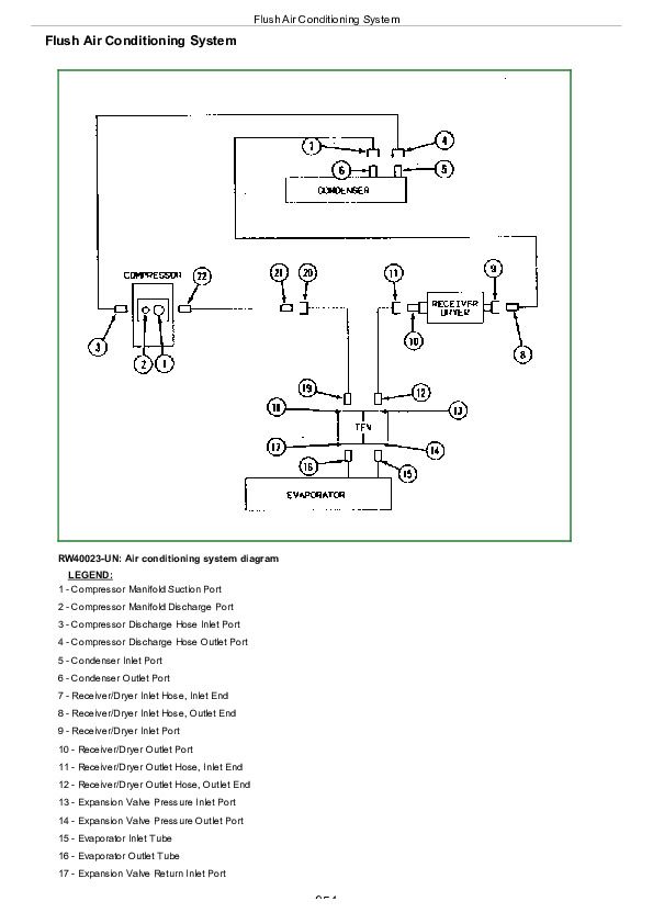
Flush Air Conditioning System................954
Evacuate Air Conditioning System................959
Charge Air Conditioning System................960
Group 35: Heating System................831
Adjust Heater Temperature Control Cable................963
Replace Heater Temperature Control Cable................965
Remove Heater Control Valve................968
Leak Test Heater Control Valve................969
Install Heater Control Valve................970
John Deere 5045E, 5055E, 5065E and 5075E (FT4) Tractors (S.No. 748241— ) Repair Service Manual (TM902519)


