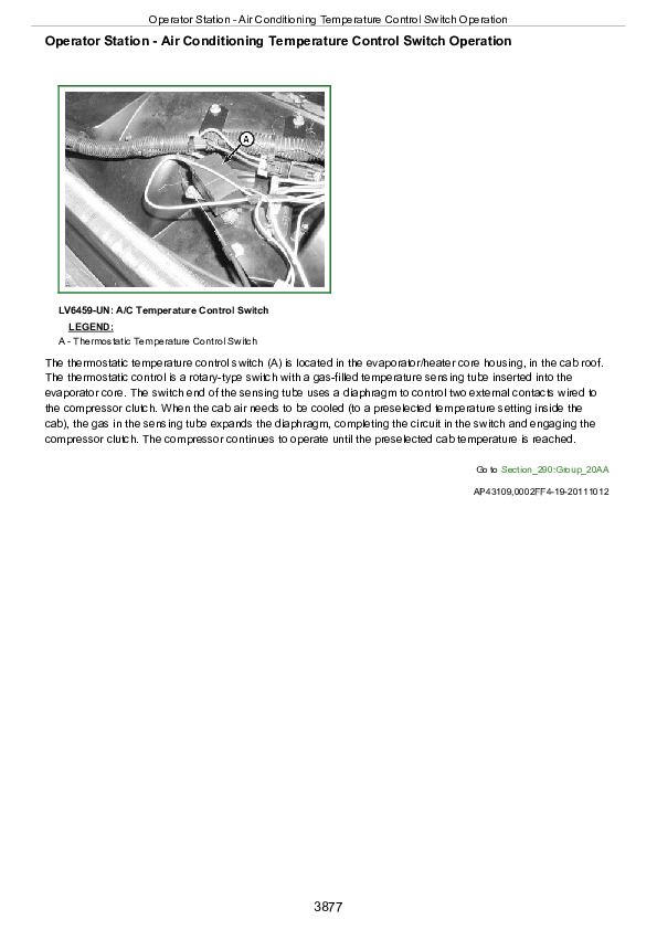
John Deere Tractors 5075M, 5085M, 5100M, 5100MH, 5100ML, 5115M, 5115ML Diagnosis and Tests Service Technical Manual (TM116519)
Catalog:
Model:
Complete Diagnosis Tests Technical Manual with electrical wiring diagrams for John Deere Tractors 5075M, 5085M, 5100M, 5100MH, 5100ML, 5115M, 5115ML (IT4/Stage IIIB), with workshop information to maintain, diagnose, repair, and service like professional mechanics.
John Deere 5075M, 5085M, 5100M, 5100MH, 5100ML, 5115M, 5115ML Tractors workshop Diagnosis & Tests technical manual includes:
* Numbered table of contents easy to use so that you can find the information you need fast.
* Detailed sub-steps expand on repair procedure information
* Numbered instructions guide you through every repair procedure step by step.
* Troubleshooting and electrical service procedures are combined with detailed wiring diagrams for ease of use.
* Notes, cautions and warnings throughout each chapter pinpoint critical information.
* Bold figure number help you quickly match illustrations with instructions.
* Detailed illustrations, drawings and photos guide you through every procedure.
* Enlarged inset helps you identify and examine parts in detail.
tm116519 English - John Deere 5075M (FT4_Stage IIIB), 5085M, 5100M, 5100MH, 5100ML, 5115M and 5115ML (IT4_Stage IIIB) Tractors Diagnosis and Tests Technical Manual.pdf
tm116528 French - Manuel technique de diagnostic des tracteurs 5075M (FT4/Phase IIIB), 5085M, 5100M, 5100MH, 5100ML, 5115M et 5115ML (IT4/Phase IIIB)
tm116529 German - Technisches Handbuch zur Diagnose der Traktoren 5075M (FT4/Stufe IIIB), 5085M, 5100M, 5100MH, 5100ML, 5115M und 5115ML (IT4/Stufe IIIB)
tm116539 Italian - Manuale tecnico per la diagnosi dei trattori 5075M (FT4/Stage IIIB), 5085M, 5100M, 5100MH, 5100ML, 5115M e 5115ML (IT4/Stage IIIB)
tm116558 Romanian - Manual tehnic de diagnosticare pentru tractoare 5075M (FT4/Etapa IIIB), 5085M, 5100M, 5100MH, 5100ML, 5115M şi 5115ML (IT4/Etapa IIIB)
tm116567 Swedish - 5075M (FT4/Steg IIIB), 5085M, 5100M, 5100MH, 5100ML, 5115M och 5115ML (IT4/Steg IIIB) Traktorer felsökningshandbok
tm116578 Norwegian - Tekniske diagnosehåndbøker for traktorene 5075M (FT4/trinn IIIB), 5085M, 5100M, 5100MH, 5100ML, 5115M og 5115ML (IT4/trinn IIIB)
Total Pages: 3,958 pages
File Format: PDF (bookmarked, ToC, Searchable, Printable)
Language: English
MAIN SECTIONS
Foreword
General Information
Safety
General References
Technical Specific References
Diagnostic Trouble Codes
BCU Code Diagnostics
CCU Code Diagnostics
ECU Code Diagnostics
EIC Code Diagnostics
HCU Code Diagnostics
ICC Code Diagnostics
PTR Code Diagnostics
Observable Symptoms and System Diagnostics
General References
Engine Diagnostics
Fuel, Air Intake, Exhaust, and Cooling Diagnostics
Electrical Diagnostics
Electronic Control Unit Diagnostics
Drive Systems and Transmission Diagnostics
Steering and Brakes Diagnostics
Hydraulic Diagnostics
Cab/Open Operator`s Station Diagnostics
Engine
General References
Engine Calibrations, Preliminary Checks and Operational Checks
Engine Theory of Operation
Engine Schematics
Engine Component and Connector Information
Engine Tests and Adjustments
Fuel, Air Intake, Exhaust, and Cooling
General References
Fuel, Air Intake, Exhaust, and Cooling Calibrations, Preliminary
and Operational Checks
Fuel, Air Intake, Exhaust, and Cooling Theory of Operation
Fuel, Air Intake, Exhaust, and Cooling Schematics
Fuel, Air Intake, Exhaust, and Cooling Component and Connector
Information
Fuel, Air Intake, Exhaust, and Cooling Tests and Adjustments
Electrical General and Theory of Operation
General References
Turn Signal Switch and Warning Lights
Wipers (Two Speed)
Wipers (Single Speed)
Rear Wipers
Instrument Cluster Control (ICC)
Basic Control Unit (BCU)
Electrohydraulic Control Unit (EHC)
Hitch Control Unit (HCU)
Power Train Reverser (PTR)
Chassis Control Unit (CCU) (PR/SR Transmission)
Chassis Control Unit (CCU) (SS Transmission)
Engine Control Unit (ECU)
Controller Area Network
Electrical Schematics
General References
Starting, Charging and Battery Disconnect (SE1)
Neutral Start (SS Transmission) (SE2A)
Neutral Start (PR/SR Transmission) (SE2B)
Accessory Power (SE3)
Horn (SE4)
Light Switch, Headlights, and Signal Lights (SE5)
Cab Work Lighting (SE5A)
Open Operator Station Work Lighting (SE5B)
Turn Signal Switch and Warning Lights (SE6)
Light Switch, Headlights and Signal Lights (License and Clearance
Lights) (SE7)
Cab Work Lighting (License and Clearance Lights) (SE7A)
Open Operator Station Work Lighting (License and Clearance Lights)
(SE7B)
Warning and Turn Signal Lighting (License and Clearance Lights)
(SE8)
Junction Block Power (SE9)
Trailer Connector (SE10)
Trailer Connector (Implement Flood Light Connector) (SE11A)
Front Implement Interfaces (SE11B)
Loader Lights (SE12)
Back-Up Alarm (SE13A)
Beacon Light (SE13B)
Mid-Mount SCV (SE14)
Power Outlets (Square Terminals) (SE15A)
Power Outlets (Round Terminals) (SE15B)
Heating (SE16)
Air Conditioning (SE17)
Wipers (Two Speed) (SE19)
Wipers (Single Speed) (SE20)
Rear Wipers (SE21)
Dome Light, Door Switch, and Radio (SE22)
Air Seat (SE23)
Instrument Cluster Control (ICC) (SE24)
Ground Drive PTO, Seat, Rear PTO and Wheel Speed (SE25A)
Front PTO (SE25B)
Multi-Function Control Lever (SE25C)
ELX Relay and Fuses (SE26)
Mechanical Front-Wheel Drive (MFWD) (SE27)
Brake Switch (SE28)
Electrohydraulic Control Unit (EHC) (SE29A)
Hitch Control Unit (HCU) (SE29B)
Power Train Reverser (PTR) (SE29C)
Chassis Control Unit (CCU) (PR/SR Transmission) (SE29D)
Chassis Control Unit (CCU) (SS Transmission) (SE29E)
Engine Control Unit (ECU) (SE30)
Fuel Preheater (License and Clearance Lights) (SE31)
Controller Area Network (SE32)
Electrical Components and Connectors
General References
Starting and Charging (SE1)
Neutral Start (SS Transmission) (SE2A)
Neutral Start (PR/SR Transmission) (SE2B)
Accessory Power (SE3)
Horn (SE4)
Light Switch, Headlights, and Signal Lights (SE5)
Cab Work Lighting (SE5A)
Open Operator Station Work Lighting (SE5B)
Turn Signal Switch and Warning Lights (SE6)
Light Switch, Headlights and Signal Lights (License and Clearance
Lights) (SE7)
Cab Work Lighting (License and Clearance Lights) (SE7A)
Open Operator Station Work Lighting (License and Clearance Lights)
(SE7B)
Warning Light Switch and Turn Signal Lighting (License and Clearance
Lights) (SE8)
Junction Block Power (SE9)
Trailer Connector (SE10)
Trailer Connector (Implement Flood Light Connector) (SE11A)
Front Implement (SE11B)
Loader Lights (SE12)
Back-Up Alarm (SE13A)
Beacon Light (SE13B)
Mid-Mount SCV (SE14)
Power Outlets (Square Terminals) (SE15A)
Power Outlets (Round Terminals) (SE15B)
Heating (SE16)
Air Conditioning (SE17)
Wipers (Two Speed) (SE19)
Wipers (Single Speed) (SE20)
Rear Wipers (SE21)
Dome Light, Door Switch and Radio (SE22)
Air Seat (SE23)
Instrument Cluster Control (ICC) (SE24)
Ground Drive PTO, Seat, Rear PTO, and Wheel Speed (SE25A)
Front PTO (SE25B)
Multi-Function Control Lever (SE25C)
ELX Relay and Fuses (SE26)
Mechanical Front-Wheel Drive (MFWD) (SE27)
Brake Switch (SE28)
Electrohydraulic Control Unit (EHC) (SE29A)
Hitch Control Unit (HCU) (SE29B)
Power Train Reverser (PTR) (SE29C)
Chassis Control Unit (CCU) (PR/SR Transmission) (SE29D)
Chassis Control Unit (CCU) (SS Transmission) (SE29E)
Engine Control Unit (ECU) (SE30)
Fuel Preheater (License and Clearance Lights) (SE31)
Controller Area Network (SE32)
Fuses and Relays
Ground Points
Interconnects
Wiring Harnesses
Electrical Tests and Adjustments
General References
Starting and Charging
Neutral Start (SS Transmission)
Neutral Start (PR/SR Transmission)
Accessory Power
Horn
Light Switch, Headlights, and Signal Lights
Cab Work Lighting
Open Operator Station Work Lighting
Turn Signal Switch and Warning Lights
Light Switch, Headlights and Signal Lights (License and Clearance
Lights)
Cab Work Lighting (License and Clearance Lights)
Open Operator Station Work Lighting (License and Clearance Lights)
Warning and Turn Signal Lighting (License and Clearance Lights)
Junction Block Power
Trailer Connector
Trailer Connector (Implement Flood Light Connector)
Front Implement Interfaces
Loader Lights
Back-Up Alarm
Beacon Light
Mid-Mount SCV
Power Outlets (Square Terminals)
Power Outlets (Round Terminals)
Heating
Air Conditioning
Wipers (Two Speed)
Wipers (Single Speed)
Rear Wipers
Dome Light, Door Switch and Radio
Air Seat
Instrument Cluster Control (ICC)
Ground Drive PTO, Seat, Rear PTO, and Wheel Speed
Front PTO
Multi-Function Control Lever
ELX Relay and Fuses
Mechanical Front-Wheel Drive (MFWD)
Brake Switch
Electrohydraulic Control Unit (EHC)
Hitch Control Unit (HCU)
Power Train Reverser (PTR)
Chassis Control Unit (CCU) (PR/SR Transmission)
Chassis Control Unit (CCU) (SS Transmission)
Engine Control Unit (ECU)
Fuel Preheater
Controller Area Network
Electronic Control Units
General References
Calibrations, Preliminary Checks and Operational Checks
Theory of Operation
Schematics
Component and Connector Information
Tests and Adjustments
Basic Control Unit (BCU)
Chassis Control Unit (CCU)
Engine Control Unit (ECU)
Engine Interface Control Unit (EIC)
Hitch Control Unit (HCU)
Instrument Cluster Control Unit (ICC)
Power Train Reverser (PTR)
Drive Systems and Transmissions
General References
Calibrations, Preliminary Checks and Operational Checks
Creeper Theory of Operation
Differential Theory of Operation
Differential Lock Theory of Operation
Final Drive Theory of Operation
Front PTO Theory of Operation
Rear PTO Theory of Operation
High Crop Axle Theory of Operation
MFWD Theory of Operation
PR/SR Transmission Theory of Operation
PR Plus Transmission Theory of Operation
SS Transmission Theory of Operation
Drive Systems Schematics
Transmission Schematics
Drive Systems Component and Connector Information
Transmission Component and Connector Information
Drive Systems Tests and Adjustments
Transmission Tests and Adjustments
Steering and Brakes
General References
Brake Calibrations, Preliminary Checks and Operational Checks
Steering Calibrations, Preliminary Checks and Operational Checks
Brake Theory of Operation
Secondary Brake Theory of Operation
Steering Theory of Operation
Brake Schematics
Steering Schematics
Brake Component and Connector Information
Secondary Brake Component and Connector Information
Steering Component and Connector Information
Brake Tests and Adjustments
Secondary Brake Tests and Adjustments
Steering Tests and Adjustments
Hydraulics
General References
Calibrations, Preliminary Checks and Operational Checks
General Hydraulics Theory of Operation
Electrohydraulic Hitch Theory of Operation
Mechanical Hitch Theory of Operation
Front Hitch Theory of Operation
Hydraulic Filter Theory of Operation
Hydraulic Pump Theory of Operation
Dual Mid-Mount SCV Theory of Operation-Mono-Block Valve
Power Beyond Theory of Operation-Mono-Block Valve
Quick Disconnect Coupler Theory of Operation
Dual Rear SCV Theory of Operation-Mono-Block Valve
Triple Mid-Mount SCV Theory of Operation-Mono-Block Valve
Triple Rear SCV Theory of Operation-Mono-Block Valve
Dual Mid-Mount SCV Theory of Operation-Sectional Valve
Power Beyond Theory of Operation-Sectional Valve
Dual Rear SCV Theory of Operation-Sectional Valve
Triple Mid-Mount SCV Theory of Operation-Sectional Valve
Triple Rear SCV Theory of Operation-Sectional Valve
Hydraulic Trailer Brake Theory of Operation
Schematics-Mono-Block Valve
Schematics-Sectional Valve
Component and Connector Information
Tests and Adjustments
Cab/Open Operator`s Station
General References
Calibrations, Preliminary Checks and Operational Checks
HVAC Theory of Operation
Seat Theory of Operation
Schematics
Component and Connector Information
Tests and Adjustments
Special Tools
General References
Dealer Fabricated and Service Tools
TABLE OF CONTENTS
Section 210: General Information................59
Group 05A: Safety................59
Work In Ventilated Area................62
Recognize Safety Information................63
Avoid Backover Accidents................64
Prevent Machine Runaway................65
Avoid Contact with Agricultural Chemicals................66
Clean Vehicle of Hazardous Pesticides................68
Use a Safety Chain................69
Work in Clean Area................70
Decommissioning: Proper Recycling and Disposal of Fluids and Components................71
Avoid Harmful Asbestos Dust................72
Avoid Hot Exhaust................73
Clean Exhaust Filter Safely................74
Handle Fuel Safely—Avoid Fires................77
Prepare for Emergencies................78
Handle Fluids Safely—Avoid Fires................79
Avoid High-Pressure Fluids................80
Install All Guards................81
Use Proper Lifting Equipment................82
Illuminate Work Area Safely................83
Live With Safety................84
Service Machines Safely................85
Support Machine Properly................86
Remove Paint Before Welding or Heating................87
Park Machine Safely................88
Stay Clear of Rotating Drivelines................89
Follow Safety Instructions................91
Use Proper Tools................92
Service Tires Safely................93
Keep ROPS Installed Properly................94
Construct Dealer-Made Tools Safely................95
Practice Safe Maintenance................96
Understand Signal Words................97
Replace Safety Signs................98
Avoid Heating Near Pressurized Fluid Lines................99
Wear Protective Clothing................100
Service Accumulator Systems Safely................101
Handling Batteries Safely................102
Handle Agricultural Chemicals Safely................104
Service Cooling System Safely................106
Use Steps and Handholds Correctly................107
Transport Tractor Safely................108
Group 05B: General References................60
General Information - Summary of References................110
Regions and Country Versions................111
Deliver Safely................113
Glossary of Terms................115
Information Available in Sections, Groups and Subgroups................119
Trademarks................120
Group 05C: Technical Specific References................60
Features and Accessories................125
Metric Bolt and Screw Torque Values................128
Unified Inch Bolt and Screw Torque Values................130
Section 211: Diagnostic Trouble Codes................133
Group BCU: BCU Code Diagnostics................133
BCU 000168.16 - Control Unit Supply Voltage Too High................133
BCU 000168.17 - Control Unit Supply Voltage Moderately Low................133
BCU 000168.18 - Control Unit Supply Voltage Extremely Low................133
BCU 000629.12 - BCU Control Unit Fault................133
BCU 001882.02 - Front PTO Speed Sensor Circuit Voltage High................133
BCU 001882.15 - Front PTO Speed Sensor Circuit, Speed Present With Front PTO Off................133
BCU 001882.17 - Front PTO Speed Sensor Circuit, Speed Not Present With Front PTO On................133
BCU 001893.07 - Front PTO Switch Fault................133
BCU 523438.02 - BCU Control Unit Internal Fault................133
BCU 523905.31 - Front PTO Solenoid Valve Circuit Fault................133
BCU 524055.11 - BCU Control Unit Internal Fault................133
BCU 524216.31 - Front PTO On at Power-Up................133
Group CCU: CCU Code Diagnostics................133
CCU 000090.03 - Rear PTO Oil Temperature Sensor Circuit Voltage High................133
CCU 000090.04 - Rear PTO Oil Temperature Sensor Circuit Voltage Low................133
CCU 000096.03 - Fuel Level Sensor Circuit Voltage High................133
CCU 000096.04 - Fuel Level Sensor Circuit Voltage Low................133
CCU 000237.02 - VIN Security Data Conflict................133
CCU 000237.14 - VIN Security Not Enabled................133
CCU 000237.31 - VIN Security Messages Missing................133
CCU 000567.05 - Front Differential Lock Solenoid Circuit Fault................133
CCU 000569.05 - Rear Differential Lock Solenoid Circuit Fault................133
CCU 000628.02 - CCU EOL Data Fault................133
CCU 000629.12 - CCU Control Unit Fault................133
CCU 000630.14 - Rear PTO Configuration Invalid................133
CCU 000976.04 - Rear PTO WEO Sensor Open................133
CCU 001638.00 - Hydraulic Oil Temperature Very Hot................133
CCU 001638.03 - Hydraulic Oil Temperature Sensor Circuit Voltage High................133
CCU 001638.04 - Hydraulic Oil Temperature Sensor Circuit Voltage Low................133
CCU 001638.16 - Hydraulic Oil Temperature High................133
CCU 001883.00 - Rear PTO Overspeed................133
CCU 001883.01 - Rear PTO Underspeed................134
CCU 002818.31 - Operator Presence Switch Not Activated................134
CCU 003509.03 - Sensor Supply Voltage Out of Range High................134
CCU 003509.04 - Sensor Supply Voltage Out of Range Low................134
CCU 522384.14 - Rear PTO High Reverse................134
CCU 523316.04 - CCU Switched Supply Voltage Low................134
CCU 523839.02 - Secondary Brake Switch Conflict................134
CCU 523844.12 - Diff Lock Braking Disabled................134
CCU 523907.02 - PTO Remote Enable Switch Conflict................134
CCU 523908.02 - Rear PTO External Switch Conflict................134
CCU 524037.02 - MFWD Switch Circuit Fault................134
CCU 524223.03 - Differential Lock Circuit Voltage High................134
CCU 524224.14 - PTO Switch Voltage Mismatch................134
CCU 524235.05 - MFWD Solenoid Circuit Fault................134
CCU 524252.05 - Rear PTO Solenoid Circuit Fault................134
CCU 524255.31 - Rear Remote PTO Enabled................134
Group ECU: ECU Code Diagnostics................134
ECU - Non-Tractor ECU Codes................134
ECU 000084.31 - ECU Calculated Vehicle Speed and CAN bus Vehicle Speed Mismatch................134
ECU 000152.12 - Control Unit Fault................134
ECU 000152.14 - Control Unit Fault................134
ECU 000152.16 - Control Unit Fault................134
ECU 000237.02 - VIN Security Data Invalid................134
ECU 000237.13 - VIN Option Code Security Data Conflict................134
ECU 000237.31 - VIN Security Data Missing................134
ECU 000647.03 - Engine Fan Clutch Output Device Driver Voltage Above Normal, Or Shorted To High Source................134
ECU 000647.05 - Engine Fan Drive Circuit Has High Resistance................134
ECU 000647.06 - Engine Fan Clutch Output Device Driver Current Above Normal, Or Grounded Circuit................134
ECU 000695.19 - Unapproved Engine Speed Request................134
ECU 000876.05 - Air Conditioner Compressor Clutch Circuit Open................134
ECU 000876.06 - Air Conditioner Compressor Clutch Circuit Short To Ground................134
ECU 001069.31 - Tire Size Error................134
ECU 001110.31 - Engine Protection Shutdown................135
ECU 001351.05 - Air Brake Compressor Clutch open circuit................135
ECU 001351.06 - Air Brake Compressor Clutch Short To Ground................135
ECU 001550.05 - Air Conditioner Compressor Clutch Under-Current................135
ECU 001550.06 - Air Conditioner Compressor Clutch Over-Current................135
ECU 002659.02 - EGR Flow Rate Mismatch................135
ECU 003353.31 - Alternator Not Charging With Engine Running................135
ECU 003695.03 - Diesel Particulate Filter Regeneration Inhibit Switch Shorted To Battery................135
ECU 003695.04 - Diesel Particulate Filter Regeneration Inhibit Switch Shorted To Ground................135
ECU 003695.05 - Diesel Particulate Filter Regeneration Inhibit Switch Circuit Open................135
ECU 003695.13 - Diesel Particulate Filter Regeneration Inhibit Switch Out Of Calibration................135
ECU 003695.14 - Diesel Particulate Filter Regeneration Special Instructions................135
ECU 003696.03 - Diesel Particulate Filter Regeneration Force Switch Shorted To Battery................135
ECU 003696.04 - Diesel Particulate Filter Regeneration Force Switch Shorted To Ground................135
ECU 003696.05 - Diesel Particulate Filter Regeneration Force Switch Current Low................135
ECU 003711.14 - Exhaust Temperature Management Failure Special Instructions................135
ECU 003711.31 - DOC Inlet Temperature Not Reached During ETM................135
ECU 524225.31 - Engine Start Protection Bypass Detected................135
Group EIC: EIC Code Diagnostics................135
EIC 000628.02 - EIC EOL Data Fault................135
EIC 000628.12 - EIC Programming Fault................135
EIC 000630.13 - EIC Calibration Fault/Not Calibrated................135
EIC 001237.31 - Failed Key Authentication................135
EIC 002000.09 - ECU Message Missing................135
EIC 003695.14 - Diesel Particulate Filter Regeneration Fault................135
EIC 003719.15 - Diesel Particulate Filter Regeneration Fault................135
EIC 521214.11 - Immobilizer Control Device Fault................135
EIC 521321.12 - Immobilizer Control Device Fault................135
EIC 521322.31 - Immobilizer Control Device Fault................135
EIC 523702.14 - EIC Control Unit Fault................135
EIC 523702.31 - EIC Control Unit Fault................135
Group HCU: HCU Code Diagnostics................135
HCU 000168.04 - Unswitched Supply Voltage Low................135
HCU 000190.02 - Rear Hitch Calibration Fault/Engine Speed Low................136
HCU 000444.03 - Switched Supply Voltage High/Rear Hitch Solenoids................136
HCU 000629.12 - HCU Control Unit Fault................136
HCU 000630.13 - HCU Calibration Fault/Not Calibrated................136
HCU 000639.14 - HCU Communication Fault................136
HCU 001638.02 - HCU Calibration Fault/Hydraulic Oil Temperature Low................136
HCU 001873.02 - Rear Hitch Position Sensor Circuit Voltage Fault................136
HCU 001873.03 - Rear Hitch Position Sensor Circuit Voltage High................136
HCU 001873.04 - Rear Hitch Position Sensor Circuit Voltage Low................136
HCU 001873.11 - Rear Hitch Position Sensor Fault................136
HCU 001873.13 - HCU Calibration Fault/Rear Hitch Position Sensor Circuit................136
HCU 001881.03 - Rear Hitch Draft Sensor Circuit Voltage High................136
HCU 001881.04 - Rear Hitch Draft Sensor Circuit Voltage Low................136
HCU 001881.13 - HCU Calibration Fault/Rear Hitch Draft Sensor Circuit................136
HCU 002071.09 - CCU Message Missing................136
HCU 003509.03 - Sensor Supply Voltage Out of Range High................136
HCU 003509.04 - HCU Sensor Supply Voltage Low................136
HCU 003509.06 - Sensor Supply Circuit Current High or Grounded Circuit................136
HCU 520870.02 - HCU Memory Error................136
HCU 521000.02 - Rear Hitch External Switch Circuit Fault................136
HCU 521000.31 - Rear Hitch External Switch Circuit Conflict................136
HCU 521001.02 - Rear Hitch Raise Valve Current Out of Range................136
HCU 521001.03 - Rear Hitch Raise Valve Circuit Voltage High................136
HCU 521001.04 - Rear Hitch Raise Valve Circuit Voltage Low................136
HCU 521001.05 - Rear Hitch Raise Solenoid Current Low................136
HCU 521001.06 - Rear Hitch Raise Solenoid Current High................136
HCU 521001.07 - HCU Calibration Fault/Rear Hitch Raise Solenoid................136
HCU 521001.11 - HCU Calibration Fault/Rear Hitch Raise Solenoid................136
HCU 521001.13 - HCU Calibration Fault/Rear Hitch Raise Solenoid................136
HCU 521002.03 - Rear Hitch Lower Valve Circuit Voltage High................136
HCU 521002.04 - Rear Hitch Lower Valve Circuit Voltage Low................136
HCU 521002.05 - Rear Hitch Lower Solenoid Current Low................136
HCU 521002.06 - Rear Hitch Lower Solenoid Current High................136
HCU 521002.07 - HCU Calibration Fault/Rear Hitch Lower Solenoid................137
HCU 521002.11 - HCU Calibration Fault/Rear Hitch Lower Solenoid................137
HCU 521002.13 - HCU Calibration Fault/Rear Hitch Lower Solenoid................137
HCU 523832.03 - Rear Hitch Rate-of-Drop Sensor Circuit Voltage High................137
HCU 523832.04 - Rear Hitch Rate-of-Drop Sensor Circuit Voltage Low................137
HCU 523832.13 - HCU Calibration Fault/Rear Hitch Rate-of-Drop Control................137
HCU 523833.03 - Rear Hitch Raise-Limit Control Circuit Voltage High................137
HCU 523833.04 - Rear Hitch Raise-Limit Control Circuit Voltage Low................137
HCU 523833.13 - HCU Calibration Fault/Rear Hitch Raise-Limit Control................137
HCU 523834.03 - Rear Hitch Control Lever Sensor Circuit Voltage High................137
HCU 523834.04 - Rear Hitch Control Lever Sensor Circuit Voltage Low................137
HCU 523834.13 - Hitch Calibration Fault/Rear Hitch Control Lever Sensor................137
HCU 523842.03 - Rear Hitch Load/Depth Sensor Circuit Voltage High................137
HCU 523842.04 - Rear Hitch Load/Depth Sensor Circuit Voltage Low................137
HCU 523842.13 - Rear Hitch Load Depth Control Fault/Out of Calibration................137
HCU 523843.02 - Rear Raise/Lower Switch Circuit Fault................137
HCU 523843.15 - Rear Hitch Control Switch Position Fault................137
HCU 523843.19 - Rear Hitch Control Switch Communication Fault................137
HCU 523843.31 - Rear Hitch Control Switch Communication Fault................137
HCU 523910.02 - HCU Control Unit Fault................137
HCU 523950.13 - HCU Calibration Fault/Position Sensor................137
HCU 523952.31 - Rear Hitch Disabled/HCU Configuration................137
HCU 524016.04 - HCU Switched Supply Voltage Low................137
Group ICC: ICC Code Diagnostics................137
ICC 000107.00 - Air Filter Restricted................137
ICC 000167.04 - Alternator Voltage Below Normal................137
ICC 000237.02 - ICC VIN Security Mismatch................137
ICC 000237.31 - ICC VIN Security Missing................137
ICC 000628.12 - ICC Programming Fault................137
ICC 000630.02 - ICC Calibration Memory Fault................137
ICC 002818.31 - Operator Presence Switch Not Activated................137
Group PTR: PTR Code Diagnostics................137
PTR 000084.07 - Excessive Wheel Speed Detected During Calibration................137
PTR 000158.01 - System Switched Voltage Low................138
PTR 000162.02 - High/Low Switch Circuit Conflict................138
PTR 000162.31 - High, Low Switch Stuck On................138
PTR 000190.18 - Engine Speed Missing During Shift................138
PTR 000191.00 - Excessive Top Shaft Speed During Calibration................138
PTR 000191.17 - Top Shaft Speed Too Low................138
PTR 000598.02 - Clutch Switch Open With Pedal Up................138
PTR 000598.04 - Clutch Switch Signal Failed Low................138
PTR 000628.02 - EOL Data Fault................138
PTR 000629.12 - PTR Control Unit Fault................138
PTR 000630.14 - Tractor Model Out Of Range/Transmission Calibration Value High................138
PTR 000752.03 - Power Shuttle Potentiometer Input Voltage High................138
PTR 000752.04 - Power Shuttle Potentiometer Input Voltage Low................138
PTR 001504.10 - Seat Switch Closed Too Long................138
PTR 002820.31 - Operator Not Present During Shift................138
PTR 002825.07 - Not Valid Neutral Park Command................138
PTR 003509.03 - PTR Sensor Supply Voltage High................138
PTR 003509.04 - PTR Sensor Supply Voltage Low................138
PTR 521233.05 - High Valve Driver Fault................138
PTR 521234.05 - Low Valve Driver Fault................138
PTR 521235.05 - Reverse Valve Driver Fault................138
PTR 522456.07 - Speed Control Lever Park and Neutral Switch Conflict................138
PTR 522456.31 - Speed Control Lever Transition Without Using Clutch Pedal................138
PTR 523953.02 - Speed Control Lever Sensor Circuit Conflict................138
PTR 523959.31 - No Wheel Speed While in Gear................138
PTR 523966.31 - Come Home Detected................138
PTR 524020.31 - Reverser in Gear at Power-Up................138
PTR 524021.31 - Directional Reverser Lever Switch Circuit Fault................138
PTR 524160.02 - Not Valid Neutral/Not Neutral Switch................138
PTR 524173.02 - Clutch Pedal Compare Error................138
PTR 524173.14 - Sync Lever Shift Without Clutch Pedal Engaged................138
PTR 524173.15 - Clutch Pedal Voltage High................138
PTR 524173.16 - Both Clutch Pedals Voltage High................138
PTR 524173.17 - Clutch Pedal Voltage Low................139
PTR 524173.18 - Both Clutch Pedals Voltage Low................139
PTR 524230.05 - Enable Valve Driver Fault................139
PTR 524230.07 - Enable Valve Stuck................139
PTR 524234.03 - Pressure Sensor Voltage High................139
PTR 524234.04 - Pressure Sensor Voltage Low................139
PTR 524254.03 - Transmission Enable Valve Power High................139
PTR 524254.04 - Transmission Enable Valve Power Low................139
PTR 524267.15 - High Speed Shuttle Shift................139
Section 212: Observable Symptoms and System Diagnostics................458
Group 05B: General References................458
Observable Symptoms and System Diagnostics - Summary of References................464
Group 20: Engine Diagnostics................458
Engine System Problems................458
Group 30: Fuel, Air Intake, Exhaust, and Cooling Diagnostics................458
Fuel and Air System Problems................458
Group 40: Electrical Diagnostics................458
Back-Up Alarm Problems................458
Charging System Problems................458
Door Switch and Dome Lamp Problems................458
Electrical Connector Problems................458
Horn Problems................458
Lighting System Problems................458
Power Outlet Problems................458
Starting System Problems................458
Trailer Connector and Junction Block Problems................458
Group 45: Electronic Control Unit Diagnostics................458
CAN System Diagnosis................458
Chassis Control Unit (CCU) Problems................458
Codes After Adding / Removing Control Units................458
Control Unit Problems................458
Control Unit Programming Failed................458
Control Unit System Diagnosis................458
Basic Control Unit (BCU) Problems................458
Engine Control Unit (ECU) Problems................458
Hitch Control Unit (HCU) Problems................458
Instrument Cluster Control (ICC) Problems................458
Power Train Reverser (PTR) Problems................458
Programming Multiple Control Units................458
Group 50: Drive Systems and Transmission Diagnostics................458
Front PTO Problems................458
Front PTO System Diagnosis................459
MFWD Problems................459
MFWD System Diagnosis................459
PowrReverser Transmission Problems................459
PowrReverser Transmission System Diagnosis................459
SyncReverser Transmission Problems................459
SyncReverser Transmission System Diagnosis................459
SyncShuttle Transmission Problems................459
SyncShuttle Transmission System Diagnosis................459
Rear Differential Lock Problems................459
Rear Differential Lock System Diagnosis................459
Rear PTO Problems................459
Rear PTO System Diagnosis................459
Group 60: Steering and Brakes Diagnostics................459
Brake Problems................459
Brake System Diagnosis................459
Steering Problems................459
Steering System Diagnosis................459
Group 70: Hydraulic Diagnostics................459
EH Hitch Problems................459
EH Hitch System Diagnosis................459
Hydraulic Trailer Brake Problems................459
Hydraulic Trailer Brake System Diagnosis................459
Mechanical Hitch Problems................459
Mechanical Hitch System Diagnosis................459
Mid-Mount SCV Problems................459
Mid-Mount SCV System Diagnosis................459
Rear SCV Problems................459
Rear SCV System Diagnosis................459
Group 90: Cab/Open Operator's Station Diagnostics................459
HVAC Problems................459
HVAC System Diagnosis................459
Park Position Problems................459
Radio Problems................460
Seat Problems................460
Wiper Problems................460
Section 220: Engine................609
Group 05B: General References................609
Engine - Summary of References................611
Engine Information................612
Group 10AA: Engine Calibrations, Preliminary Checks and Operational Checks................614
Engine Calibrations, Preliminary Checks and Operational Checks................614
Group 20AA: Engine Theory of Operation................616
Engine Theory of Operation................616
Group 30AA: Engine Schematics................618
Engine Schematics................618
Group 40AA: Engine Component and Connector Information................609
Engine Components................623
Group 50AA: Engine Tests and Adjustments................609
Engine Test Procedures and Adjustments................628
Engine Performance Testing................629
Engine Performance Variables................632
Section 230: Fuel, Air Intake, Exhaust, and Cooling................634
Group 05B: General References................634
Fuel, Air Intake, Exhaust, and Cooling - Summary of References................636
Fuel, Air Intake, Exhaust, and Cooling Information................637
Group 10AA: Fuel, Air Intake, Exhaust, and Cooling Calibrations, Preliminary and Operational Checks................634
Fuel and Air System Calibrations, Preliminary and Operational Checks................639
Group 20AA: Fuel, Air Intake, Exhaust, and Cooling Theory of Operation................634
Air Intake System Theory of Operation................642
Cooling System Theory of Operation................644
Exhaust System Theory of Operation................646
Fuel System Theory of Operation................647
Group 30AA: Fuel, Air Intake, Exhaust, and Cooling Schematics................651
Fuel, Air Intake, Exhaust, and Cooling Schematics................651
Group 40AA: Fuel, Air Intake, Exhaust, and Cooling Component and Connector Information................653
Fuel, Air Intake, Exhaust, and Cooling Component and Connector Information................653
Group 50AA: Fuel, Air Intake, Exhaust, and Cooling Tests and Adjustments................655
Fuel, Air Intake, Exhaust, and Cooling Tests and Adjustments................655
Section 240A: Electrical General and Theory of Operation................656
Group 05B: General References................656
Electrical General and Theory of Operation - Summary of References................661
Circuit Malfunctions................664
Circuit Types................667
Electrical Designators................669
Electrical Procedure................670
Electrical Schematic Symbols................674
Reading Wiring Schematics and Diagrams................677
Relay Circuit Types................681
Troubleshooting Unresolved Electrical/Electronic Problems................694
Using a Digital Multimeter................695
Using a Probe Light................697
Visually Inspect Electrical System................699
Wiring Diagram and Schematic Information................700
Group 20DD: Turn Signal Switch and Warning Lights................656
Turn Signal Switch and Warning Lights Theory of Operation................703
Group 20MA: Wipers (Two Speed)................656
Front Wiper Switch (Two Speed) Theory of Operation................706
Group 20MB: Wipers (Single Speed)................656
Front Wiper Switch (Single Speed) Theory of Operation................708
Group 20MC: Rear Wipers................656
Rear Wiper Switch Theory of Operation................710
Group 20PA: Instrument Cluster Control (ICC)................656
Instrument Cluster Control (ICC) Theory of Operation................714
Instrument Cluster Alarm Theory of Operation................717
Group 20QB: Basic Control Unit (BCU)................656
Basic Control Unit (BCU) Theory of Operation................719
Group 20UA: Electrohydraulic Control Unit (EHC)................656
Electrohydraulic Control Unit (EHC) Theory of Operation................721
Group 20UB: Hitch Control Unit (HCU)................656
Hitch Control Unit (HCU) Theory of Operation................726
Hitch Quick Raise/Lower Assembly Theory of Operation................730
Load/Depth Sensor Theory of Operation................732
Hitch Position Sensor Theory of Operation................733
Left External Raise/Lower Switch Theory of Operation................734
Left External Raise/Lower Switch Theory of Operation (with Right External Raise/Lower Switch)................735
Right External Raise/Lower Switch Theory of Operation................736
Hitch Raise Solenoid Theory of Operation................737
Hitch Lower Solenoid Theory of Operation................738
Group 20UC: Power Train Reverser (PTR)................657
Power Train Reverser (PTR) Theory of Operation................748
Group 20UD: Chassis Control Unit (CCU) (PR/SR Transmission)................657
Chassis Control Unit (CCU) Theory of Operation (PR/SR Transmission)................761
Fuel Level Sensor Theory of Operation (PR/SR Transmission)................765
Group 20UE: Chassis Control Unit (CCU) (SS Transmission)................657
Chassis Control Unit (CCU) Theory of Operation (SS Transmission)................767
Fuel Level Sensor Theory of Operation (SS Transmission)................768
Group 20VA: Engine Control Unit (ECU)................657
Engine Control Unit (ECU) Theory of Operation................770
Group 20WA: Controller Area Network................657
CAN Communication System Theory Of Operation................773
Section 240B: Electrical Schematics................775
Group 05B: General References................775
Electrical Schematics - Summary of References................783
Group 30AA: Starting, Charging and Battery Disconnect (SE1)................775
Starting, Charging and Battery Disconnect Schematic and Circuit Diagram (SE1)................793
Group 30AB: Neutral Start (SS Transmission) (SE2A)................775
Neutral Start Schematic and Circuit Diagram (SS Transmission) (SE2A)................803
Group 30AC: Neutral Start (PR/SR Transmission) (SE2B)................775
Neutral Start Schematic and Circuit Diagram (PR/SR Transmission) (SE2B)................811
Group 30BA: Accessory Power (SE3)................775
Accessory Power Schematic and Circuit Diagram (SE3)................819
Group 30CA: Horn (SE4)................775
Horn Schematic and Circuit Diagram (SE4)................827
Group 30DA: Light Switch, Headlights, and Signal Lights (SE5)................775
Light Switch, Headlights, and Signal Lights Schematic and Circuit Diagram (SE5)................839
Group 30DB: Cab Work Lighting (SE5A)................775
Cab Work Lighting Schematic and Circuit Diagram (SE5A)................850
Group 30DC: Open Operator Station Work Lighting (SE5B)................775
Open Operator Station Work Lighting Schematic and Circuit Diagram (SE5B)................856
Group 30DD: Turn Signal Switch and Warning Lights (SE6)................775
Turn Signal Switch and Warning Lights Schematic and Circuit Diagram (SE6)................863
Group 30EA: Light Switch, Headlights and Signal Lights (License and Clearance Lights) (SE7)................775
Light Switch, Headlights and Signal Lights Schematic and Circuit Diagram (with License and Clearance Lights) (SE7)................872
Group 30EB: Cab Work Lighting (License and Clearance Lights) (SE7A)................775
Cab Work Lighting Schematic and Circuit Diagram (with License and Clearance Lights) (SE7A)................880
Group 30EC: Open Operator Station Work Lighting (License and Clearance Lights) (SE7B)................775
Open Operator Station Work Lighting Schematic and Circuit Diagram (with License and Clearance Lights) (SE7B)................886
Group 30ED: Warning and Turn Signal Lighting (License and Clearance Lights) (SE8)................775
Warning and Turn Signal Lighting Schematic and Circuit Diagram (with License and Clearance Lights) (SE8)................894
Group 30FA: Junction Block Power (SE9)................775
Junction Block Power Schematic and Circuit Diagram (SE9)................903
Group 30GA: Trailer Connector (SE10)................776
Trailer Connector Schematic and Circuit Diagram (SE10)................911
Group 30GB: Trailer Connector (Implement Flood Light Connector) (SE11A)................776
Trailer Connector Schematic and Circuit Diagram (with Implement Flood Light Connector) (SE11A)................919
Group 30GC: Front Implement Interfaces (SE11B)................776
Front Implement Interfaces Schematic and Circuit Diagram (with License and Clearance Lights) (SE11B)................927
Group 30HA: Loader Lights (SE12)................776
Loader Lights Schematic and Circuit Diagram (SE12)................939
Group 30IA: Back-Up Alarm (SE13A)................776
Back-Up Alarm Schematic and Circuit Diagram (SE13A)................953
Group 30IB: Beacon Light (SE13B)................776
Beacon Light Schematic and Circuit Diagram (SE13B)................963
Group 30JA: Mid-Mount SCV (SE14)................776
Mid-Mount SCV Schematic and Circuit Diagram (SE14)................971
Group 30KA: Power Outlets (Square Terminals) (SE15A)................776
Power Outlets Schematic and Circuit Diagram (with Square Terminals) (SE15A)................979
Group 30KB: Power Outlets (Round Terminals) (SE15B)................776
Power Outlets Schematic and Circuit Diagram (with Round Terminals) (SE15B)................987
Group 30LA: Heating (SE16)................776
Heating Schematic and Circuit Diagram (SE16)................994
Group 30LB: Air Conditioning (SE17)................776
Air Conditioning Schematic and Circuit Diagram (SE17)................1000
Group 30MA: Wipers (Two Speed) (SE19)................776
Wipers Schematic and Circuit Diagram (Two Speed) (SE19)................1006
Group 30MB: Wipers (Single Speed) (SE20)................776
Wipers Schematic and Circuit Diagram (Single Speed) (SE20)................1012
Group 30MC: Rear Wipers (SE21)................776
Rear Wipers Schematic and Circuit Diagram (SE21)................1018
Group 30NA: Dome Light, Door Switch, and Radio (SE22)................776
Dome Light, Door Switch, and Radio Schematic and Circuit Diagram (SE22)................1025
Group 30OA: Air Seat (SE23)................777
Air Seat Schematic and Circuit Diagram (SE23)................1032
Group 30PA: Instrument Cluster Control (ICC) (SE24)................777
Instrument Cluster Control (ICC) Schematic and Circuit Diagram (SE24)................1045
Group 30QA: Ground Drive PTO, Seat, Rear PTO and Wheel Speed (SE25A)................777
Ground Drive PTO, Seat Switch, Rear PTO Switch and Wheel Speed Sensor Schematic and Circuit Diagram (SE25A)................1062
Group 30QB: Front PTO (SE25B)................777
Front PTO Schematic and Circuit Diagram (SE25B)................1072
Group 30QC: Multi-Function Control Lever (SE25C)................777
Multi-Function Control Lever Schematic and Circuit Diagram (SE25C)................1081
Group 30RA: ELX Relay and Fuses (SE26)................777
ELX Relay and Fuses Schematic and Circuit Diagram (SE26)................1091
Group 30SA: Mechanical Front-Wheel Drive (MFWD) (SE27)................777
Mechanical Front-Wheel Drive (MFWD) Schematic and Circuit Diagram (SE27)................1101
Group 30TA: Brake Switch (SE28)................777
Brake Switch Schematic and Circuit Diagram (SE28)................1113
Group 30UA: Electrohydraulic Control Unit (EHC) (SE29A)................777
Electrohydraulic Control Unit (EHC) Schematic and Circuit Diagram (SE29A)................1125
Group 30UB: Hitch Control Unit (HCU) (SE29B)................777
Hitch Control Unit (HCU) Schematic and Circuit Diagram (SE29B)................1134
Group 30UC: Power Train Reverser (PTR) (SE29C)................777
Power Train Reverser (PTR) Schematic and Circuit Diagram (SE29C)................1141
Group 30UD: Chassis Control Unit (CCU) (PR/SR Transmission) (SE29D)................777
Chassis Control Unit (CCU) Schematic and Circuit Diagram (PR/SR Transmission) (SE29D)................1153
Group 30UE: Chassis Control Unit (CCU) (SS Transmission) (SE29E)................777
Chassis Control Unit (CCU) Schematic and Circuit Diagram (SS Transmission) (SE29E)................1166
Group 30VA: Engine Control Unit (ECU) (SE30)................777
Engine Control Unit (ECU) Schematic and Circuit Diagram (4045 Engine) (SE30)................1175
Engine Control Unit (ECU) Schematic and Circuit Diagram (3029 Engine) (SE30)................1179
Group 30VB: Fuel Preheater (License and Clearance Lights) (SE31)................777
Fuel Preheater Schematic and Circuit Diagram (with License and Clearance Lights) (SE31)................1186
Group 30WA: Controller Area Network (SE32)................778
Controller Area Network Schematic and Circuit Diagram (SE32)................1193
Section 240C: Electrical Components and Connectors................1197
Group 05B: General References................1197
Electrical Components and Connectors - Summary of References................1228
Group 40AA: Starting and Charging (SE1)................1197
F26 (125A) Master Fuse................1247
F35 (2A) Battery Disconnect Fuse................1249
G01 Battery................1251
G02 Alternator................1253
K14 Battery Disconnect Relay................1255
K57 Battery Disconnect Relay................1257
M01 Starter Motor/Solenoid................1259
S01 Key Switch................1261
S28 Battery Disconnect Switch................1263
Group 40AB: Neutral Start (SS Transmission) (SE2A)................1197
K18 Neutral Start Relay (SS Transmission)................1267
S03 Neutral Start Switch................1269
V01 Diode Block (SS Transmission)................1271
Group 40AC: Neutral Start (PR/SR Transmission) (SE2B)................1197
K11 Neutral Relay................1275
K18 Neutral Start Relay (PR/SR Transmission)................1277
V01 Diode Block (PR/SR Transmission)................1279
Group 40BA: Accessory Power (SE3)................1197
K07 Accessory Relay................1283
Group 40CA: Horn (SE4)................1197
H01 Horn................1287
S05 Horn Switch................1289
Group 40DA: Light Switch, Headlights, and Signal Lights (SE5)................1197
E01 Right Front High/Low Beam Headlight................1293
E02 Left Front High/Low Beam Headlight................1295
H02 Right Tail/Turn Light................1297
H03 Left Tail/Turn Light................1299
H08 Left Brake Light................1301
H09 Right Brake Light................1303
H12 Right Tail/Turn Light................1305
H13 Left Tail/Turn Light................1307
H14 Right Rear Tail/Turn/Warning Light................1309
H15 Left Rear Tail/Turn/Warning Light................1312
K27 Headlight Relay................1314
K28 High/Low Beam Light Relay................1316
S06 Light Switch................1318
S12 High/Low Beam Flash to Pass Switch................1321
Group 40DB: Cab Work Lighting (SE5A)................1198
E03 Left Front Work Light................1325
E04 Right Front Work Light................1327
E05 Left Rear Work Light................1329
E06 Right Rear Work Light................1331
E07 Left Front Work Light................1333
E08 Right Front Work Light................1335
E09 Right Rear Work Light................1337
E10 Left Rear Work Light................1339
Group 40DC: Open Operator Station Work Lighting (SE5B)................1198
E11 Left Rear Work Light................1344
E12 Right Rear Work Light................1347
E13 Right Front Work Light................1350
E14 Left Front Work Light................1352
Group 40DD: Turn Signal Switch and Warning Lights (SE6)................1198
H04 Right Front Warning Light................1356
H05 Left Front Warning Light................1358
H10 Right Rear Warning Light................1360
H11 Left Rear Warning Light................1362
H19 Right Rear Warning Light................1364
H20 Left Rear Warning Light................1366
S07 Turn Signal Switch................1368
Group 40EA: Light Switch, Headlights and Signal Lights (License and Clearance Lights) (SE7)................1198
E01 Right Front High/Low Beam Headlight (with License and Clearance Lights)................1373
E02 Left Front High/Low Beam Headlight (with License and Clearance Lights)................1375
E17 License Plate Light (with License and Clearance Lights)................1377
E19 License Plate Light (with License and Clearance Lights)................1379
E20 License Plate Light (with License and Clearance Lights)................1381
H02 Right Tail/Turn Light (with License and Clearance Lights)................1383
H03 Left Tail/Turn Light (with License and Clearance Lights)................1385
H16 Right Front Position/Turn/Warning Light (with License and Clearance Lights)................1387
H17 Left Front Position/Turn/Warning Light (with License and Clearance Lights)................1389
H21 Right Rear Tail/Turn/Brake/Warning/Clearance Light (with License and Clearance Lights)................1391
H22 Left Rear Tail/Turn/Brake/Warning/Clearance Light (with License and Clearance Lights)................1394
K27 Headlight Relay (with License and Clearance Lights)................1397
K28 High/Low Beam Light Relay (with License and Clearance Lights)................1399
S06 Light Switch (with License and Clearance Lights)................1401
S12 High/Low Beam Flash to Pass Switch (with License and Clearance Lights)................1404
Group 40EB: Cab Work Lighting (License and Clearance Lights) (SE7A)................1199
E31 Left Rear Work Light (with License and Clearance Lights)................1408
E32 Right Rear Work Light (with License and Clearance Lights)................1410
E33 Left Front Work Light (with License and Clearance Lights)................1412
E34 Right Front Work Light (with License and Clearance Lights)................1414
E35 Left Rear Work Light (with License and Clearance Lights)................1416
E36 Right Rear Work Light (with License and Clearance Lights)................1418
E37 Left Front Work Light (with License and Clearance Lights)................1420
E38 Right Front Work Light (with License and Clearance Lights)................1422
S22 Front Work Light Switch (with License and Clearance Lights)................1424
S24 Rear Work Light Switch (with License and Clearance Lights)................1427
Group 40EC: Open Operator Station Work Lighting (License and Clearance Lights) (SE7B)................1199
E11 Left Rear Work Light (with License and Clearance Lights)................1432
E12 Right Rear Work Light (with License and Clearance Lights)................1434
E13 Right Front Work Light (with License and Clearance Lights)................1436
E14 Left Front Work Light (with License and Clearance Lights)................1438
Group 40ED: Warning Light Switch and Turn Signal Lighting (License and Clearance Lights) (SE8)................1199
K30 Flasher Logic Relay (with License and Clearance Lights)................1443
S07 Turn Signal Switch (with License and Clearance Lights)................1446
S10 Warning Light Switch (with License and Clearance Lights)................1449
Group 40FA: Junction Block Power (SE9)................1200
X02 Junction Block................1454
Group 40GA: Trailer Connector (SE10)................1200
X01 Trailer Connector................1459
Group 40GB: Trailer Connector (Implement Flood Light Connector) (SE11A)................1200
X01_1 Trailer Connector (with Implement Flood Light Connector)................1463
X01_2 Implement Flood Light Connector................1465
Group 40GC: Front Implement (SE11B)................1200
K35 Left Front Turn Relay................1469
K36 Right Front Turn Relay................1471
X883 Outlet Implement Lighting and Accessory Connector (Front)................1473
Group 40HA: Loader Lights (SE12)................1200
E15 Left Front Loader Light................1477
E16 Right Front Loader Light................1479
E21 Right Front High/Low Beam/Clearance Light (with License and Clearance Lights)................1481
E22 Left Front High/Low Beam/Clearance Light (with License and Clearance Lights)................1484
S26 Loader Light Switch................1487
Group 40IA: Back-Up Alarm (SE13A)................1200
B20 Reverse Switch................1493
H06 Back-Up Alarm................1495
Group 40IB: Beacon Light (SE13B)................1200
H07 Beacon Light................1500
S25 Beacon Light Switch................1503
Group 40JA: Mid-Mount SCV (SE14)................1200
K25 Mid-Mount SCV Retract (Black) 3rd Function Relay................1509
K26 Mid-Mount SCV Extend (Gray) 3rd Function Relay................1512
S19 Mid-Mount SCV 3rd Function Switch................1515
Y03 Mid-Mount SCV Retract (Black) 3rd Function Solenoid Valve................1517
Y04 Mid-Mount SCV Extend (Gray) 3rd Function Solenoid Valve................1519
Group 40KA: Power Outlets (Square Terminals) (SE15A)................1201
X03 Convenience Outlet (Convenience Outlet with Square Terminals)................1523
X05 Auxiliary Power Strip (Convenience Outlet with Square Terminals)................1525
X06 Power Outlet (Convenience Outlet with Square Terminals)................1527
Group 40KB: Power Outlets (Round Terminals) (SE15B)................1201
X04 Convenience Outlet (Convenience Outlet with Round Terminals)................1532
X05 Auxiliary Power Strip (Convenience Outlet with Round Terminals)................1534
X06 Power Outlet (Convenience Outlet with Round Terminals)................1536
Group 40LA: Heating (SE16)................1201
M02 Left HVAC Blower Motor................1541
M03 Right HVAC Blower Motor................1543
R03 HVAC Resistor................1545
S08 HVAC Blower Switch................1547
Group 40LB: Air Conditioning (SE17)................1201
B07 A/C Deicing Switch................1551
B08 A/C High/Low Pressure Switch................1553
M04 A/C Compressor Clutch................1555
S09 A/C ON/OFF Switch................1557
Group 40MA: Wipers (Two Speed) (SE19)................1201
M05 Front Wiper Motor (Two Speed)................1561
M06 Front Washer Pump (Two Speed)................1563
S30 Front Wiper Switch (Two Speed)................1565
Group 40MB: Wipers (Single Speed) (SE20)................1201
K37 Intermittent Wiper Relay................1569
M05_1 Front Wiper Motor (Single Speed)................1571
M06 Front Washer Pump (Single Speed)................1573
S30_1 Front Wiper Switch (Single Speed)................1575
Group 40MC: Rear Wipers (SE21)................1201
M07 Rear Wiper Motor................1579
M08 Rear Washer Pump................1581
S11 Rear Wiper Switch................1583
Group 40NA: Dome Light, Door Switch and Radio (SE22)................1201
A03 Dome Light and Switch Assembly................1587
A04 Radio/Clock Assembly................1589
B240 Right Speaker................1591
B241 Left Speaker................1593
E18 Right-Side Console Light................1595
S13 Left Door Switch................1597
X08 Radio Connector................1599
Group 40OA: Air Seat (SE23)................1202
A05 Air Seat Assembly................1603
Group 40PA: Instrument Cluster Control (ICC) (SE24)................1202
A01 Instrument Cluster Control (ICC)................1606
A01X1 Instrument Control Cluster (ICC) Connector................1607
A01X2 Instrument Control Cluster (ICC) Connector................1609
A01X3 Instrument Control Cluster (ICC) Connector................1611
A01X4 Instrument Control Cluster (ICC) Connector................1613
H18 Instrument Cluster Alarm................1615
S36 Roll Mode Switch................1618
Group 40QA: Ground Drive PTO, Seat, Rear PTO, and Wheel Speed (SE25A)................1202
B10 Wheel Speed Sensor................1622
H35 Ground Drive PTO Indicator Light................1624
S02 Rear PTO ON/OFF Switch................1626
S02_1 Rear PTO ON/OFF Switch................1629
S04 Seat Switch................1631
S37 Ground Drive PTO Switch................1633
Group 40QB: Front PTO (SE25B)................1202
A10 Basic Control Unit (BCU)................1636
A10X1 Basic Control Unit (BCU) Connector................1637
A10X2 Basic Control Unit (BCU) Connector................1640
A10X3 Basic Control Unit (BCU) Connector................1644
B66 Front PTO Speed Sensor................1647
F39 (10A) Basic Control Unit (BCU) Fuse................1649
F41 (10A) Front PTO Service ADVISOR™ Fuse................1651
H36 Front PTO Indicator Light................1653
S29 Front PTO Switch................1655
X22 Front PTO Service ADVISOR™ Connector................1657
Y09 Front PTO Solenoid................1659
Group 40QC: Multi-Function Control Lever (SE25C)................1203
A11 Multi-Function Control Lever Controller................1663
S48 Multi-Function Control Lever Switch with Hi-Lo................1665
Y26 Multi-Coupler................1667
Group 40RA: ELX Relay and Fuses (SE26)................1203
ELX Relay and Fuses Component and Connectors................1670
Group 40SA: Mechanical Front-Wheel Drive (MFWD) (SE27)................1203
S16 Auto MFWD Switch................1675
S16_1 MFWD Switch................1679
S16_2 MFWD Switch................1683
Group 40TA: Brake Switch (SE28)................1203
S17 Brake Pedal Switch................1688
Group 40UA: Electrohydraulic Control Unit (EHC) (SE29A)................1203
A06 Electrohydraulic Control Unit (EHC)................1691
A06X1 Electrohydraulic Control Unit (EHC) Connector................1692
A06X2 Electrohydraulic Control Unit (EHC) Connector................1696
A06X3 Electrohydraulic Control Unit (EHC) Connector................1701
Group 40UB: Hitch Control Unit (HCU) (SE29B)................1203
A06D Hitch Control Unit (HCU)................1706
A08 Hitch Quick Raise/Lower Assembly................1707
B17 Load/Depth Sensor................1710
B18 Hitch Draft Sensor................1712
B19 Hitch Position Sensor................1714
S21 Left External Raise/Lower Switch................1716
S21 Left External Raise/Lower Switch (with Right External Raise/Lower Switch)................1718
S27 Right External Raise/Lower Switch................1720
Y830 Hitch Raise Solenoid Valve................1722
Y831 Hitch Lower Solenoid Valve................1724
Group 40UC: Power Train Reverser (PTR) (SE29C)................1203
A06A Power Train Reverser (PTR)................1727
B09 Top Shaft Speed Sensor................1728
B12 Enable Pressure Sensor................1730
B13 Clutch Pedal Position Sensor................1732
B21 Power Shuttle Control................1734
S14 Forward Neutral Reverse (FNR) Switch................1736
S15 Clutch Pedal Disengage Switch................1738
S18 Park Switch................1740
S23 High/Low Shifter Switch................1742
S34 Speed Lever Neutral Switch................1744
Y05 Transmission Forward (Low) Solenoid Valve................1746
Y06 Transmission Reverse Solenoid Valve................1748
Y07 Clutch Enable Solenoid Valve................1750
Y10 Transmission Forward (High) Solenoid Valve................1752
Group 40UD: Chassis Control Unit (CCU) (PR/SR Transmission) (SE29D)................1204
A06B Chassis Control Unit (CCU) (PR/SR Transmission)................1755
B01 Fuel Level Sensor (PR/SR Transmission)................1756
B06 Rear PTO Speed Sensor (PR/SR Transmission)................1758
B11 Hydraulic Oil Temperature Sensor (PR/SR Transmission)................1760
S20 Differential Lock Switch (PR/SR Transmission)................1762
S31 Remote PTO Enable Switch (PR/SR Transmission)................1764
S32 Right Fender PTO ON/OFF Switch (PR/SR Transmission)................1766
S33 Secondary Brake Switch (PR/SR Transmission)................1768
S50 Left Fender PTO ON/OFF Switch (PR/SR Transmission)................1770
Y01 PTO Solenoid Valve (PR/SR Transmission)................1772
Y02 MFWD Solenoid (PR/SR Transmission)................1774
Y11 Differential Lock Solenoid Valve (PR/SR Transmission)................1776
Group 40UE: Chassis Control Unit (CCU) (SS Transmission) (SE29E)................1204
A06C Chassis Control Unit (CCU) (SS Transmission)................1779
B01 Fuel Level Sensor (SS Transmission)................1780
B06 Rear PTO Speed Sensor (SS Transmission)................1782
B11 Hydraulic Oil Temperature Sensor (SS Transmission)................1784
S20 Differential Lock Switch (SS Transmission)................1786
Y01 PTO Solenoid Valve (SS Transmission)................1788
Y02 MFWD Solenoid (SS Transmission)................1790
Y11 Differential Lock Solenoid Valve (SS Transmission)................1792
Group 40VA: Engine Control Unit (ECU) (SE30)................1205
A09 Engine Control Unit (ECU)................1795
A09X1 Engine Control Unit (ECU) Connector................1796
A09X2 Engine Control Unit (ECU) Connector................1797
A09X3 Engine Control Unit (ECU) Connector................1798
B03 Air Filter Restriction Switch................1802
B23 Hand Throttle Position Sensor................1803
B32 Foot Throttle Position Sensor................1807
B42 Electronic Fan Speed Sensor................1810
B44 Engine Crankshaft Speed Sensor................1811
B45 Engine Camshaft Speed Sensor................1812
B47 Crankcase Pressure Sensor................1813
B48 Intake Manifold Pressure Sensor................1814
B49 EGR Valve................1815
B51 Compressor Inlet Humidity/Pressure/Temperature Sensor................1816
B52 EGR Temperature Sensor................1817
B53 Intercooler Outlet Temperature Sensor................1818
B54 Manifold Air Temperature Sensor................1819
B55 Rail Pressure Sensor................1820
B56 Engine Oil Pressure Sensor................1821
B57 Exhaust Manifold Pressure Sensor................1822
B58 Water In Fuel Sensor................1823
B59 Coolant Temperature Sensor................1824
B60 Fuel Temperature Sensor................1825
B61 Fuel Pressure Sensor................1826
B62 DPF Delta Pressure Sensor................1827
B63 After Treatment Air Temperature Sensor................1830
F5005 (50A) Glow Plug Relay Fuse................1833
K5803 Glow Plug Relay................1835
K38 Air Heater Relay................1837
M09 Electronic Fan Motor................1838
M11 Exhaust Throttle Actuator................1839
S35 Exhaust Filter Cleaning Switch................1840
X12 Electronic Fan Drive Connector................1842
X13 Relay Driver................1843
Y21 Cylinder 1 Fuel Injector................1844
Y22 Cylinder 2 Fuel Injector................1845
Y23 Cylinder 3 Fuel Injector................1846
Y24 Cylinder 4 Fuel Injector................1847
Y25 High Pressure Fuel Pump SCV................1848
Group 40VB: Fuel Preheater (License and Clearance Lights) (SE31)................1206
F42 (15A) Fuel Preheater Fuse................1851
K34 Fuel Preheater Relay................1853
R04 Fuel Preheater................1855
Group 40WA: Controller Area Network (SE32)................1206
A911 CAN Terminator (Cab/Operator Station)................1859
A912 CAN Terminator (Chassis)................1861
X10 Service ADVISOR™ Connector................1864
Group 40ZA: Fuses and Relays................1206
Load Center Fuses and Relays................1882
Load Center Fuses and Relays (with License and Clearance Lights)................1897
Group 40ZB: Ground Points................1206
Ground Point Locations................1909
XGND1 Single Point Ground................1911
XGND2 Operator Station Chassis Ground................1913
XGND3 Vehicle Chassis Ground................1915
XGND5 Right Beacon Light Ground (OOS)................1917
XGND6 Left Beacon Light Harness Ground (OOS)................1919
XGND7 Right Beacon Light Harness Ground (Cab)................1921
XGND9 Cab Roof Ground................1923
XGND11 Evaporator Ground................1925
XGND12 Front Wiper Ground................1927
XGND15 Left Beacon Light Harness Ground (Cab)................1929
Group 40ZC: Interconnects................1207
XSP1 Circuit 050 Splice Pack................1933
X09 Engine/Cab Power/Chassis Harness to Left Front Junction Block................1935
X11 Engine/After Treatment Interface Connector................1937
X14 Single Pin Deutsch Engine Harness Connector to Chassis................1939
X16 Left Rear Junction Block to Cab Power Harness................1942
X17 Cab-Chassis Harness to Convenience Outlet................1944
X18 Cab/Chassis to Multi-Function Control Lever (Loader Connector)................1946
X19 Cab to Multi-Function Control Lever (Loader Connector)................1948
X20 Chassis to Multi-Function Control Lever (Loader Suspension)................1950
X21 Chassis to Multi-Function Control Lever (Hi/Lo Shift)................1952
Section 240D: Electrical Tests and Adjustments................2135
Group 05B: General References................2135
Electrical Tests and Adjustments - Summary of References................2148
Group 50AA: Starting and Charging................2135
Battery Inspection Test................2163
Charging System Circuit Test................2171
Starting System Circuit Test (SS Transmission)................2174
Starting System Circuit Test (PR/SR Transmission)................2179
Battery Disconnect Circuit Test................2185
Group 50AB: Neutral Start (SS Transmission)................2135
Neutral Start Circuit Test (SS Transmission)................2190
Group 50AC: Neutral Start (PR/SR Transmission)................2135
Neutral Start Circuit Test (PR/SR Transmission)................2192
Group 50BA: Accessory Power................2135
Accessory Power Circuit Test................2197
Group 50CA: Horn................2135
Horn Circuit Test................2204
Group 50DA: Light Switch, Headlights, and Signal Lights................2135
Light Switch Circuit Test................2209
Headlight Circuit Test................2211
Signal Lights Circuit Test................2225
Group 50DB: Cab Work Lighting................2135
Cab Front Work Light Circuit Test................2231
Cab Rear Work Light Circuit Test................2234
Group 50DC: Open Operator Station Work Lighting................2135
Open Operator Station Front and Rear Work Light Circuit Test................2240
Group 50DD: Turn Signal Switch and Warning Lights................2135
Right Turn Signal Light Circuit Test................2250
Left Turn Signal Light Circuit Test................2257
Group 50EA: Light Switch, Headlights and Signal Lights (License and Clearance Lights)................2135
Light Switch Circuit Test (with License and Clearance Lights)................2265
Headlight Circuit Test (with License and Clearance Lights)................2267
Signal Light Circuit Test (with License and Clearance Lights)................2275
License Plate Light Circuit Test (with License and Clearance Lights)................2276
Clearance Light Circuit Test (with License and Clearance Lights)................2277
Group 50EB: Cab Work Lighting (License and Clearance Lights)................2136
Cab Front Work Light Circuit Test (with License and Clearance Lights)................2288
Cab Rear Work Light Circuit Test (with License and Clearance Lights)................2292
Group 50EC: Open Operator Station Work Lighting (License and Clearance Lights)................2136
Open Operator Station Front and Rear Work Light Circuit Test (with License and Clearance Lights)................2300
Group 50ED: Warning and Turn Signal Lighting (License and Clearance Lights)................2136
Right Turn Signal Light Circuit Test (with License and Clearance Lights)................2312
Left Turn Signal Light Circuit Test (with License and Clearance Lights)................2320
Group 50FA: Junction Block Power................2136
Junction Block Power Circuit Test................2331
Group 50GA: Trailer Connector................2136
Trailer Connector Circuit Test................2337
Group 50GB: Trailer Connector (Implement Flood Light Connector)................2136
Trailer Connector Circuit Test (with Implement Flood Light Connector)................2343
Group 50GC: Front Implement Interfaces................2136
Front Implement Interfaces Circuit Test................2351
Group 50HA: Loader Lights................2136
Loader Lights Circuit Test................2365
Group 50IA: Back-Up Alarm................2136
Back-Up Alarm Circuit Test (PR/SR Transmission)................2376
Back-Up Alarm Circuit Test (SS Transmission)................2378
Group 50IB: Beacon Light................2136
Beacon Light Circuit Test................2384
Group 50JA: Mid-Mount SCV................2136
Mid-Mount SCV Retract (Black) 3rd Function Circuit Test................2391
Mid-Mount SCV Extend (Gray) 3rd Function Circuit Test................2395
Group 50KA: Power Outlets (Square Terminals)................2136
Convenience Outlet Circuit Test (Convenience Outlet with Square Terminals)................2402
Power Outlet Circuit Test (Convenience Outlet with Square Terminals)................2405
Auxiliary Power Strip Circuit Test (Convenience Outlet with Square Terminals)................2407
Group 50KB: Power Outlets (Round Terminals)................2137
Convenience Outlet Circuit Test (Convenience Outlet with Round Terminals)................2413
Power Outlet Circuit Test (Convenience Outlet with Round Terminals)................2416
Auxiliary Power Strip Circuit Test (Convenience Outlet with Round Terminals)................2418
Group 50LA: Heating................2137
Heater and Blower Circuit Test................2429
Group 50LB: Air Conditioning................2137
Air Conditioner Control and Compressor Circuit Test................2442
Group 50MA: Wipers (Two Speed)................2137
Front Wiper/Washer Circuit Test (Two Speed)................2453
Group 50MB: Wipers (Single Speed)................2137
Front Wiper/Washer Circuit Test (Single Speed)................2466
Group 50MC: Rear Wipers................2137
Rear Wiper/Washer Circuit Test................2478
Group 50NA: Dome Light, Door Switch and Radio................2137
Dome Light Circuit Test................2486
Door Switch Circuit Test................2489
Radio/Clock Circuit Test................2491
Radio Speaker Circuit Test................2500
Group 50OA: Air Seat................2137
Air Seat Circuit Test................2504
Group 50PA: Instrument Cluster Control (ICC)................2137
ICC—Instrument Cluster Control Unit Test................2510
ICC—Flasher Output Circuit Test (Turn Signal and Warning Lights)................2514
ICC—High Beam Headlight Input Circuit Test................2520
ICC—Instrument Cluster Audible Alarm Circuit Test................2522
ICC—Instrument Cluster Backlighting Circuit Test................2524
ICC—Left Turn Signal Indicator Input Circuit Test................2526
ICC—Right Turn Signal Indicator Input Circuit Test................2529
ICC—Warning Light Indicator Input Circuit Test................2532
ICC—Roll Mode Switch Circuit Test................2534
Group 50QA: Ground Drive PTO, Seat, Rear PTO, and Wheel Speed................2138
Ground Drive PTO Circuit Test................2539
Seat Switch Circuit Test................2542
Rear PTO Switch Circuit Test................2546
Wheel Speed Sensor Circuit Test................2548
Group 50QB: Front PTO................2138
BCU—Basic Control Unit Test................2555
Front PTO Circuit Test................2559
Front PTO Solenoid Circuit Test................2562
Front PTO Switch Circuit Test................2564
Front PTO Speed Sensor Circuit Test................2567
Group 50QC: Multi-Function Control Lever................2138
Multi-Function Control Lever Circuit Test................2574
Group 50RA: ELX Relay and Fuses................2138
ELX Relay and Fuses Circuit Test................2583
Group 50SA: Mechanical Front-Wheel Drive (MFWD)................2138
MFWD Switch Circuit Test (with Brake Assist/ON)................2590
MFWD Switch Circuit Test (with ON/OFF)................2593
MFWD Switch Circuit Test (with Auto/ON/Brake Assist)................2596
Group 50TA: Brake Switch................2138
Brake Switch Circuit Test................2602
Brake Light Circuit Test................2605
Group 50UA: Electrohydraulic Control Unit (EHC)................2138
EHC—Electrohydraulic Control Unit Test................2613
EHC—Electrohydraulic Control Unit Sensor Supply and Ground Circuit Test................2617
Group 50UB: Hitch Control Unit (HCU)................2138
HCU—Hitch Draft Sensor Circuit Test................2623
HCU—Hitch Position Sensor Circuit Test................2626
HCU—Hitch Quick Raise/Lower Assembly Circuit Test................2629
HCU—Hitch Raise Solenoid Circuit Test................2634
HCU—Hitch Lower Solenoid Circuit Test................2636
HCU—Left External Raise/Lower Switch Circuit Test................2638
HCU—Left External Raise/Lower Switch Circuit Test (with Right External Raise/Lower Switch)................2640
HCU—Right External Raise/Lower Switch Circuit Test................2642
HCU—Load/Depth Sensor Circuit Test................2644
Group 50UC: Power Train Reverser (PTR)................2139
PTR—Clutch Enable Pressure Sensor Circuit Test................2650
PTR—Clutch Enable Solenoid Circuit Test................2653
PTR—Clutch Pedal Position Circuit Test................2655
PTR—Clutch Pedal Switch Circuit Test................2658
PTR—Forward Neutral Reverse (FNR) Switch Circuit Test................2660
PTR—High/Low Shifter Switch Circuit Test................2663
PTR—Park Switch Circuit Test................2665
PTR—Power Shuttle Control Circuit Test................2667
PTR—Start Signal Circuit Test................2670
PTR—Top Shaft Speed Sensor Circuit Test................2672
PTR—Transmission Forward Solenoid Circuit Test (High)................2674
PTR—Transmission Forward Solenoid Circuit Test (Low)................2680
PTR—Transmission Reverse Solenoid Circuit Test................2682
PTR—Speed Lever Neutral Switch Circuit Test................2684
PTR—Come Home Mode Circuit Test................2686
Group 50UD: Chassis Control Unit (CCU) (PR/SR Transmission)................2139
CCU—Hydraulic Oil Temperature Sensor Circuit Test (PR/SR Transmission)................2690
CCU—MFWD Solenoid Circuit Test (PR/SR Transmission)................2692
CCU—Sensor Excitation Circuit Test (PR/SR Transmission)................2694
CCU—Rear PTO Solenoid Circuit Test (PR/SR Transmission)................2698
CCU—Rear PTO Speed Sensor Circuit Test (PR/SR Transmission)................2700
CCU—Secondary Brake Switch Circuit Test (PR/SR Transmission)................2702
CCU—Differential Lock Switch Circuit Test (PR/SR Transmission)................2705
CCU—Differential Lock Solenoid Circuit Test (PR/SR Transmission)................2709
CCU—Fuel Level Sensor Circuit Test (PR/SR Transmission)................2711
CCU—Remote PTO Enable Switch Circuit Test (PR/SR Transmission)................2713
CCU—Right Fender PTO ON/OFF Switch Circuit Test (PR/SR Transmission)................2716
CCU—Left Fender PTO ON/OFF Switch Circuit Test (PR/SR Transmission)................2719
Group 50UE: Chassis Control Unit (CCU) (SS Transmission)................2139
CCU—Hydraulic Oil Temperature Sensor Circuit Test (SS Transmission)................2724
CCU—MFWD Solenoid Circuit Test (SS Transmission)................2726
CCU—Sensor Excitation Circuit Test (SS Transmission)................2728
CCU—Rear PTO Solenoid Circuit Test (SS Transmission)................2732
CCU—Rear PTO Speed Sensor Circuit Test (SS Transmission)................2734
CCU—Differential Lock Switch Circuit Test (SS Transmission)................2736
CCU—Differential Lock Solenoid Circuit Test (SS Transmission)................2740
CCU—Fuel Level Sensor Circuit Test (SS Transmission)................2742
Group 50VA: Engine Control Unit (ECU)................2140
ECU—Engine Control Unit Test................2748
ECU—Exhaust Filter Cleaning Switch Circuit Test................2752
ECU—Hand Throttle Position Sensor Circuit Test................2756
ECU—Foot Throttle Position Sensor Circuit Test................2759
Group 50VB: Fuel Preheater................2140
Fuel Preheater Circuit Test................2765
Group 50WA: Controller Area Network................2140
CAN Network Voltage Checks................2772
Section 245: Electronic Control Units................2776
Group 05B: General References................2776
Electronic Control Units - Summary of References................2795
Control Unit Addresses - Access................2805
Recall, Record, and Clear Codes................2811
Address 200-251 — General Control Unit Data................2816
Programming Control Units................2820
Control Unit Locations and Identification................2823
VIN Security Fault Diagnosis................2827
Servicing Electronic Control Units................2829
Welding Near Electronic Control Units................2830
Keep Electronic Control Unit Connectors Clean................2831
Group 10AA: Calibrations, Preliminary Checks and Operational Checks................2776
Control Unit Calibration Procedures................2833
Group 20AA: Theory of Operation................2776
Control Unit Theory of Operation................2835
Group 30AA: Schematics................2776
Control Unit Schematics and Diagrams................2837
Group 40AA: Component and Connector Information................2776
Control Unit Connectors and Components................2839
Group 50AA: Tests and Adjustments................2776
Control Unit Tests and Adjustments................2841
Group BCU: Basic Control Unit (BCU)................2776
BCU 000 — Initial Address................2843
BCU 001 — Recall Diagnostic Codes................2844
BCU 002 — System Beep Address................2845
BCU 003 — Front PTO Speed Signal Status................2847
BCU 007 — Front PTO Switch Status................2848
BCU 023 — Front PTO Pulses Per Revolution................2849
BCU 027 — Front PTO Set-Up................2850
BCU 030 — Sensor Set-Up................2851
BCU 032 — System Voltage Display................2852
BCU 041 — Smooth Start-Up Phase for Front PTO................2853
BCU 048 — Parameter 1 for Front PTO Modulation................2854
BCU 049 — Parameter 2 for Front PTO Modulation................2855
BCU 050 — Parameter 3 for Front PTO Modulation................2856
BCU 051 — Parameter 4 for Front PTO Modulation................2857
BCU 052 — Parameter 5 for Front PTO Modulation................2858
BCU 200-251 — General Control Unit Data................2859
Group CCU: Chassis Control Unit (CCU)................2777
Chassis Control Unit (CCU) Configuration and Calibration................2862
CCU 000 — Initial Address................2864
CCU 001 — Recall Diagnostic Codes................2865
CCU 002 — System Beep Address With Speed Sensors................2866
CCU 003 — System Beep Address Without Speed Sensors................2869
CCU 004 — Switched Supply Voltage................2871
CCU 005 — Rear PTO Speed Signal Status................2872
CCU 006 — Primary Wheel Speed Signal Status................2873
CCU 007 — Rear PTO Switch Status................2874
CCU 008 — Engine Speed Signal Status................2875
CCU 009 — Front PTO Speed Signal Status................2876
CCU 010 — Hydraulic Oil Temperature Sensor Voltage................2877
CCU 012 — Rear PTO Remote Enable/Remote Fender Switch Status................2878
CCU 013 — Primary Fuel Level Sensor Voltage................2879
CCU 014 — Primary Fuel Level Sensor Resistance................2880
CCU 015 — Sensor Reference Voltage Status................2881
CCU 024 — Secondary Hand Brake/Brake Pedal Switch Status................2882
CCU 025 — MFWD Switch Status................2883
CCU 050 — CCU Unswitched Supply Voltage................2884
CCU 051 — Sensor Reference Voltage................2885
CCU 052 — Hydraulic Oil Temperature................2886
CCU 054 — Fuel Level Percentage................2887
CCU 055 — Primary Wheel Speed................2888
CCU 058 — Rear PTO Speed................2889
CCU 059 — Engine Speed................2890
CCU 060 — Front PTO Speed................2891
CCU 063 — Differential Drive Shaft Speed................2892
CCU 064 — Engine Oil Pressure Switch Status................2893
CCU 065 — Engine Coolant Temperature................2894
CCU 066 — Engine Coolant Temperature Sensor Voltage................2895
CCU 102 — Fuel Sensor Setup................2896
CCU 103 — MFWD Configuration................2897
CCU 104 — Rear PTO Configuration 1................2898
CCU 105 — Rear PTO Configuration 2................2899
CCU 106 — Rear PTO Speed Configuration................2900
CCU 107 — Rear PTO Pulses Per Revolution................2901
CCU 108 — Front PTO Pulses per Revolution................2902
CCU 109 — Front PTO Installed................2903
CCU 111 — Rear Tire Rolling Circumference................2904
CCU 115 — Differential Lock Configuration................2906
CCU 116 — Differential Lock Switch................2907
CCU 117 — Differential Lock Disengage Wheel Speed Configuration................2908
CCU 120 — Rear PTO Valve Current................2909
CCU 129 — Enable Debug Messages Configuration / MFWD Engaged with Battery Input................2910
CCU 130 — Secondary Handbrake Configuration................2912
CCU 132 — Engine Air Heater Status................2913
CCU 133 — Engine Air Heater Configuration................2914
CCU 134 — Engine Hours Display/Input................2915
CCU 135 — Engine Function Configuration................2916
CCU 136 — Engine Elevated Idle Speed................2917
CCU 137 — Engine Low Idle Speed................2918
CCU 138 — Engine Fast Idle Speed................2919
CCU 139 — Rated Engine Speed................2920
CCU 140 — Maximum Reasonable Engine Speed................2921
CCU 200-251 — General Control Unit Data................2922
Group ECU: Engine Control Unit (ECU)................2778
Engine Control Unit (ECU) Diagnostic Address List................2927
Group EIC: Engine Interface Control Unit (EIC)................2778
Engine Interface Control Unit (EIC) Configuration and Calibration................2932
EIC 000 — Initial Address................2933
EIC 001 — Recall Diagnostic Codes................2934
EIC 002 — System Beep Address................2935
EIC 040 — After Treatment Service Cleaning Enable................2938
EIC 041 — Save Aftertreatment Inhibit Setting................2939
EIC 050 — Hand Throttle Scaled Percent................2940
EIC 051 — Foot Throttle Scaled Percent................2941
EIC 052 — Hand Throttle Basic Engine Speed................2942
EIC 053 — Foot Throttle Basic Engine Speed................2943
EIC 058 — Final Commanded Engine Speed................2944
EIC 059 — Actual Engine Speed................2945
EIC 060 — Engine Hours................2946
EIC 061 — Vehicle Hours................2947
EIC 070 — Power Management Status................2948
EIC 072 — Unfiltered Rear PTO Power................2949
EIC 073 — Unfiltered Front PTO Power................2950
EIC 075 — Intelligent Power Management PTO Boost Status................2951
EIC 076 — Intelligent Power Management PTO Boost Percent................2952
EIC 077 — Intelligent Power Management PTO Boost Power................2953
EIC 078 — Intelligent Power Management Filtered Rear PTO Power................2954
EIC 079 — Intelligent Power Management Filtered Front PTO Power................2955
EIC 080 — Intelligent Power Management Transport Boost Status................2956
EIC 081 — Intelligent Power Management PTO Transport Boost Percent................2957
EIC 082 — Intelligent Power Management PTO Transport Boost Power................2958
EIC 100 — Current Key ID................2959
EIC 101 — Key ID 1................2960
EIC 102 — Key ID 2................2961
EIC 103 — Key ID 3................2962
EIC 104 — Key ID 4................2963
EIC 105 — Key ID 5................2964
EIC 106 — Key Identification Request................2965
EIC 110 — Number of Programmed Keys................2966
EIC 111 — Current Key Number................2967
EIC 112 — Immobilizer Control Device Secure Code Status................2968
EIC 113 — Immobilizer Control Device CAN Speed Rate................2969
EIC 114 — Immobilizer Control Device Error Code................2970
EIC 115 — Immobilizer Control Device Hardware Version Number................2971
EIC 116 — Immobilizer Control Device Software Version Number................2972
EIC 180 — Field Cruise On/Off................2973
EIC 181 — Field Cruise Engine Speed Limit................2974
EIC 182 — IPM On/Off................2975
EIC 183 — Aftertreatment Operator Setting Disabled/Inhibited................2976
EIC 200-251 — General Control Unit Data................2977
Group HCU: Hitch Control Unit (HCU)................2780
Hitch Control Unit (HCU) Configuration and Calibration................2979
HCU 000 — Initial Address................2980
HCU 001 — Recall Diagnostic Codes................2981
HCU 002 — HCU System Beep Mode................2982
HCU 003 — Option Jumper Status................2984
HCU 004 — Rear Hitch Position Sensor Voltage................2985
HCU 005 — Rear Hitch Draft Sensor Voltage................2986
HCU 006 — Rear Hitch Draft Sensor #2 Voltage................2987
HCU 007 — Rear Hitch External Switch................2988
HCU 008 — Rear Hitch Command Lever Voltage................2989
HCU 009 — Rear Hitch Height Limit Control Pot Voltage................2990
HCU 010 — Rear Hitch Drop Rate Control Pot Voltage................2991
HCU 011 — Rear Hitch Load/Depth Control Pot Voltage................2992
HCU 012 — Rear Hitch QRL Control Switch Voltage................2993
HCU 013 — Rear Hitch Sensor Supply Voltage................2994
HCU 014 — Control Unit Switched Supply Voltage................2995
HCU 015 — Control Unit Unswitched Supply Voltage................2996
HCU 016 — Hitch CAN Valve Supply Voltage................2997
HCU 019 — Hydraulic Oil Temperature................2998
HCU 020 — Rear Hitch Calibration................2999
HCU 021 — Rear Hitch Configuration Option................3006
HCU 022 — Rear Hitch Lever Command................3007
HCU 023 — Percent Valve Command................3008
HCU 024 — Rear Hitch Raise Rate Adjustment................3009
HCU 025 — Rear Hitch Draft Sensor #2 Voltage Adjustment................3010
HCU 026 — Rear Hitch Draft Sensor Voltage Adjustment................3011
HCU 027 — Draft Constant Multiplier Adjustment................3012
HCU 028 — Rear Hitch Position Minimum Voltage................3013
HCU 029 — Rear Hitch Position Maximum Voltage................3014
HCU 040 — Rear Hitch Valve Command Current................3015
HCU 041 — Rear Hitch Valve Raise Feedback Current................3016
HCU 042 — Rear Hitch Valve Lower Feedback Current................3017
HCU 043 — Rear Hitch Raise Valve Current Limit................3018
HCU 044 — Rear Hitch Raise Valve Deadband Current................3019
HCU 045 — Rear Hitch Lower Valve Deadband Current................3020
HCU 080 — Rear Hitch Cylinder Speed................3021
HCU 081 — Rear Hitch Command................3022
HCU 082 — Rear Hitch Lower Setpoint................3023
HCU 083 — Rear Hitch Raise Limit Control Setting................3024
HCU 084 — Rear Hitch Drop Rate Setting................3025
HCU 085 — Rear Hitch Raise Rate Setting................3026
HCU 086 — Rear Hitch Load/Depth Mix Setting................3027
HCU 087 — Rear Hitch Slip Setting................3028
HCU 088 — Rear Hitch Slip Threshold Setting................3029
HCU 091 — Rear Hitch Transport Damping Enable/Disable................3030
HCU 092 — Rear Hitch Stabilizer Bar Setting................3031
HCU 093 — Rear Hitch Fast Lower Setting................3032
HCU 200-251 — General Control Unit Data................3033
Group ICC: Instrument Cluster Control Unit (ICC)................2781
Instrument Cluster Control Unit (ICC) Configuration and Calibration................3036
ICC 000 — Initial Address................3038
ICC 001 — Recall Diagnostic Codes................3039
ICC 002 — ICU System Beep Address................3040
ICC 005 — Switch Status................3042
ICC 006 — Indicator Status................3044
ICC 010 — Fuel Level Sender Voltage................3046
ICC 020 — Units Selection................3047
ICC 021 — Auto Clear DTC Hours................3048
ICC 022 — Backlight Dimming Percentage................3049
ICC 023 — Backlight Configuration................3050
ICC 024 — Air Filter Configuration................3051
ICC 025 — Battery Charge Configuration................3052
ICC 026 — Enable PTO Speed Display................3053
ICC 027 — Enable HI/LO Transmission Gear Display................3054
ICC 031 — Revert to Hours Status................3055
ICC 032 — ICC Flash Rate 1................3056
ICC 033 — ICC Flash Rate 2................3057
ICC 036 — Engine Coolant Warning Level................3058
ICC 037 — Engine Coolant Stop Level................3059
ICC 040 — Fuel Gauge Configuration................3060
ICC 041 — Resistance Verses Fuel Level Gauge Constant 1................3061
ICC 042 — Resistance Verses Fuel Level Gauge Constant 2................3062
ICC 043 — Resistance Verses Fuel Level Gauge Constant 3................3063
ICC 044 — Resistance Verses Fuel Level Gauge Constant 4................3064
ICC 045 — Resistance Verses Fuel Level Gauge Constant 5................3065
ICC 046 — Resistance Verses Fuel Level Gauge Constant 6................3066
ICC 047 — Resistance Verses Fuel Level Gauge Constant 7................3067
ICC 048 — Resistance Verses Fuel Level Gauge Constant 8................3068
ICC 049 — Resistance Verses Fuel Level Gauge Constant 9................3069
ICC 200-251 — General Control Unit Data................3070
Group PTR: Power Train Reverser (PTR)................2782
Power Train Reverser (PTR) Control Unit Configuration and Calibration................3073
PTR 000 — Initial Address................3075
PTR 001 — Recall Diagnostic Codes................3076
PTR 002 — PTR System Beep Mode................3077
PTR 003 — PTR System Beep Mode With Speed Sensors................3079
PTR 004 — Engine and Countershaft Speed Sensor Status................3081
PTR 005 — Come Home, Trans Enable, Clutch Pedal Switch, and Seat Switch Status................3082
PTR 006 — Forward, Neutral, Not Neutral, and Reverse Switch Status................3084
PTR 007 — Speed Lever Neutral, High, Low, and Park Switch Status................3085
PTR 008 — Trans Enable Relay, High, Low, and Reverse Driver Command................3086
PTR 009 — High, Low, and Reverse Driver Status................3088
PTR 010 — Trans Enable Solenoid Current................3089
PTR 011 — Power Shuttle Input Voltage................3090
PTR 012 — Trans Enable Pressure Sensor Voltage................3091
PTR 013 — Clutch Pedal Potentiometer Channel A Voltage................3093
PTR 014 — Clutch Pedal Potentiometer Channel B Voltage................3094
PTR 015 — Creeper Lever Position Sensor Voltage................3095
PTR 022 — Clutch Pack Overfill Protection Status................3096
PTR 032 — Clutch Pedal Position................3097
PTR 033 — Clutch Pedal Pressure Command................3098
PTR 034 — Trans Enable Actual Pressure................3099
PTR 036 — Countershaft Speed................3101
PTR 050 — PTR Switched Supply Voltage................3103
PTR 051 — PTR Sensor Supply Voltage................3104
PTR 052 — Hydraulic Oil Temperature................3105
PTR 060 — Transmission Type................3106
PTR 061 — Hydraulic Oil Type Selection................3107
PTR 062 — Temperature Offset For Alternate Hydraulic Oil................3108
PTR 063 — Transmission Calibration................3109
PTR 064 — Transmission Fill Pressure and Fill Time Calibration Values................3116
PTR 065 — Forward Valve High Fill Pressure Adjustment................3118
PTR 066 — Forward Valve High Fill Time Adjustment................3119
PTR 067 — Forward Valve Low Fill Pressure Adjustment................3120
PTR 068 — Forward Valve Low Fill Time Adjustment................3121
PTR 069 — Reverse Valve Fill Pressure Adjustment................3122
Section 250: Drive Systems and Transmissions................3138
Group 05B: General References................3138
Drive Systems and Transmissions - Summary of References................3147
Install Test Equipment 50-1................3152
Install Test Equipment 50-2................3155
Install Test Equipment 50-3................3157
Install Test Equipment 50-4................3159
Install Test Equipment 50-5................3161
Install Test Equipment 50-6................3162
Install Test Equipment 50-7................3164
Install Test Equipment 50-8................3165
Install Test Equipment 50-9................3166
Install Test Equipment 50-10................3167
Install Test Equipment 50-11................3168
Install Test Equipment 50-12................3170
Install Test Equipment 50-13................3172
Install Test Equipment 50-14................3173
Install Test Equipment 50-15................3175
Install Test Equipment 50-21................3176
Install Test Equipment 50-22................3177
Install Test Equipment 50-23................3178
Install Test Equipment 50-24................3180
Install Test Equipment 50-25................3181
Install Test Equipment 50-26................3183
Install Test Equipment 50-27................3185
Install Test Equipment 50-28................3187
Group 10AA: Calibrations, Preliminary Checks and Operational Checks................3138
PR Transmission - Operational Checks................3194
SR Transmission - Operational Checks................3200
SS Transmission - Operational Checks................3205
Transmission - Preliminary Checks................3210
Front PTO - Preliminary Checks................3214
Group 20AA: Creeper Theory of Operation................3139
Drive Systems - Creeper Operation................3222
Group 20AB: Differential Theory of Operation................3139
Drive Systems - Rear Differential and Final Drive Lubrication................3227
Drive Systems - Rear Differential Power Flow................3229
Group 20AC: Differential Lock Theory of Operation................3139
Drive Systems - Rear Differential Lock Control Valve Operation................3232
Drive Systems - Rear Differential Lock Operation................3233
Group 20AD: Final Drive Theory of Operation................3139
Drive Systems - Rear Final Drive Operation................3236
Group 20BA: Front PTO Theory of Operation................3139
Drive Systems—Front PTO Operation................3239
Drive Systems—Front PTO Hydraulic Circuit Description................3241
Drive Systems—Front PTO Solenoid Valve................3242
Drive Systems—Front PTO Hydraulic Pump................3243
Drive Systems—Front PTO Oil Cooler................3244
Group 20BB: Rear PTO Theory of Operation................3139
Drive Systems - Rear Power Take-Off Brake Control Valve Operation................3246
Drive Systems - Rear Power Take-Off Clutch Control Valve Operation................3247
Drive Systems - Rear Power Take-Off Operation................3248
Drive Systems - Rear Power Take-Off Shift Operation................3251
Group 20CA: High Crop Axle Theory of Operation................3139
Drive Systems - Rear High Crop Differential and Final Drive Operation................3262
Group 20CB: MFWD Theory of Operation................3139
Drive Systems - Front Axle Operation................3265
Drive Systems - MFWD Control Valve Operation................3266
Drive Systems - MFWD Operation................3268
Drive Systems - MFWD Power Flow Operation................3271
Group 20DA: PR/SR Transmission Theory of Operation................3139
PR/SR Transmission - Forward (Low) Clutch Operation................3276
PR/SR Transmission - Reverse Clutch Operation................3278
PR/SR Transmission - Control Valve Neutral Operation................3280
PR/SR Transmission - Control Valve Forward (Low) Operation................3281
PR/SR Transmission - Control Valve Reverse Operation................3282
PR/SR Transmission - Lubrication System Operation................3283
PR/SR Transmission - Speed Shift Power Flow Operation................3287
PR/SR Transmission - Range Shift Power Flow Operation................3289
PR/SR Transmission - Speed Shift Linkage Operation................3291
PR/SR Transmission - Range Shift Linkage Operation................3293
PR/SR Transmission - Speed Shift (Cone-Type) Synchronizer Operation................3295
PR/SR Transmission - Range Shift Collar Operation................3297
PR/SR Transmission - Forward (Low) Operation................3298
PR/SR Transmission - Reverse Operation................3300
Group 20DB: PR Plus Transmission Theory of Operation................3140
PR Plus Transmission - Forward (High) Clutch Operation................3304
PR Plus Transmission - Control Valve Neutral Operation................3306
PR Plus Transmission - Control Valve Forward (Low) Operation................3307
PR Plus Transmission - Control Valve Forward (High) Operation................3308
PR Plus Transmission - Control Valve Reverse Operation................3309
PR Plus Transmission - Forward (Low) Operation................3310
PR Plus Transmission - Forward (High) Operation................3312
PR Plus Transmission - Reverse Operation................3314
Group 20DC: SS Transmission Theory of Operation................3140
SS Transmission - Traction (Low) Clutch Operation................3318
SS Transmission - Control Valve Neutral Operation................3320
SS Transmission - Control Valve Forward/Reverse (Low) Operation................3321
SS Transmission - Lubrication System Operation................3322
SS Transmission - Speed Shift Power Flow................3326
SS Transmission - Range Shift Power Flow................3328
SS Transmission - Speed Shift Linkage Operation................3330
SS Transmission - Range Shift Linkage Operation................3332
SS Transmission - Speed Shift (Cone-Type) Synchronizer Operation................3334
SS Transmission - Range Shift Collar Operation................3335
Group 30AA: Drive Systems Schematics................3140
Drive Systems - Functional Schematic................3342
Group 30BA: Transmission Schematics................3141
PR/SR Transmission - Functional Schematic and Theory................3352
SS Transmission - Functional Schematic and Theory................3356
Group 40AA: Drive Systems Component and Connector Information................3141
Drive Systems - Overview................3361
Group 40BA: Transmission Component and Connector Information................3141
PR Transmission - Overview................3365
SR Transmission - Overview................3367
SS Transmission - Overview................3369
Group 50AA: Drive Systems Tests and Adjustments................3141
Drive Systems - Differential Lube Pressure Test................3373
Drive Systems - MFWD Leak Test................3375
Drive Systems - PTO Leak Test................3379
Drive Systems - Rear Differential Lock Leak Test................3383
Drive Systems—Front PTO Pressure Test................3387
Group 50BA: Transmission Tests and Adjustments................3141
Transmission - Preliminary Pressure Test................3391
Transmission - Traction Clutch Leak Test................3393
Transmission - Forward Clutch Leak Test................3396
Transmission - Reverse Clutch Leak Test................3400
Transmission - Low Clutch Leak Test................3404
Transmission - High Clutch Leak Test................3409
Transmission - Cooler Flow Test................3414
Transmission - Lube Pressure Test................3417
Transmission - EOV Pressure Test................3419
Transmission - Clutch Enable Pressure Test................3421
Transmission - System Pressure Test................3423
Section 260: Steering and Brakes................3425
Group 05B: General References................3425
Steering and Brakes - Summary of References................3430
Install Test Equipment 60-2................3433
Install Test Equipment 60-3................3434
Install Test Equipment 60-4................3435
Install Test Equipment 60-5................3436
Install Test Equipment 60-6................3437
Install Test Equipment 60-7................3438
Install Test Equipment 60-8................3440
Install Test Equipment 60-9................3442
Install Test Equipment 60-10................3443
Install Test Equipment 60-11................3444
Install Test Equipment 60-12................3445
Group 10AA: Brake Calibrations, Preliminary Checks and Operational Checks................3425
Brakes - Preliminary Check................3448
Brakes - Operational Test................3450
Air Brakes - Preliminary Check................3453
Group 10BA: Steering Calibrations, Preliminary Checks and Operational Checks................3425
Steering - Preliminary Check................3459
Steering - Operational Check................3462
Group 20AA: Brake Theory of Operation................3425
Brakes - Brake Pistons, Plates, and Disks Theory of Operation................3466
Brakes - Brake Valve Theory of Operation................3468
Air Brakes - Theory of Operation................3471
Group 20AB: Secondary Brake Theory of Operation................3425
Brakes - Secondary Brakes Theory of Operation................3478
Brakes - Secondary Brake Theory of Operation with Air Brakes................3482
Group 20BA: Steering Theory of Operation................3425
Steering - Gerotor Theory of Operation................3487
Steering - Steering Pump Theory of Operation................3489
Steering - Steering Valve Component Theory of Operation................3490
Steering - Steering Valve Theory of Operation................3492
Steering - Steering Valve with Anti-Cavitation and Surge Relief Valves Theory of Operation................3495
Group 30AA: Brake Schematics................3426
Brakes - System Schematics................3498
Air Brakes - System Schematic................3499
Group 30BA: Steering Schematics................3426
Steering - System Schematics................3502
Group 40AA: Brake Component and Connector Information................3426
Brakes - Component Diagrams................3506
Air Brakes - Component Diagram................3508
Group 40AB: Secondary Brake Component and Connector Information................3426
Brakes - Secondary Brake Component Diagrams................3510
Brakes - Secondary Brake with Air Brakes Component Diagram................3511
Group 40BA: Steering Component and Connector Information................3426
Steering - Component Diagrams................3514
Group 50AA: Brake Tests and Adjustments................3426
Brakes - Brake Element Leak Isolation Test................3518
Brakes - Brake Retractor Adjustment................3520
Brakes - Brake Valve Supply Test................3521
Air Brakes - Supply Coupler (Red) Test................3522
Air Brakes - System Leak Test................3524
Air Brakes - Control Coupler (Yellow) Test................3526
Air Brakes - Single-Line Coupler (Black) Test................3529
Air Brakes - Pressure Regulating Valve and Air Brake System Fill Time Tests................3532
Group 50AB: Secondary Brake Tests and Adjustments................3426
Brakes - Secondary Brake Test................3535
Brakes - Secondary Brake with Air Brakes Adjustment................3536
Group 50BA: Steering Tests and Adjustments................3426
Steering - Leak Test................3541
Steering - Preliminary Supply Pressure Test................3543
Steering - Pump Flow Test................3544
Steering - Steering Relief Pressure Test................3546
Section 270: Hydraulics................3548
Group 05B: General References................3548
Hydraulics - Summary of References................3557
Hydraulic Designators................3562
JIC Hydraulic Symbols................3563
Install Test Equipment 70-1................3566
Install Test Equipment 70-2................3568
Install Test Equipment 70-3................3570
Install Test Equipment 70-4................3571
Install Test Equipment 70-5................3573
Install Test Equipment 70-6................3576
Install Test Equipment 70-7................3577
Install Test Equipment 70-8................3578
Install Test Equipment 70-9................3579
Group 10AA: Calibrations, Preliminary Checks and Operational Checks................3548
Hydraulics - Preliminary Check................3584
Hydraulics - Operational Check................3587
Hydraulics - Rear Hitch System Operational Check................3591
Hydraulics - Hydraulic Trailer Brake System Operational Check................3593
Hydraulics - Front Hitch System Operational Check................3594
Group 20AA: General Hydraulics Theory of Operation................3548
Hydraulics - Overview ( -July 2013)................3600
Hydraulics - Overview (July 2013- )................3603
Group 20BA: Electrohydraulic Hitch Theory of Operation................3548
Hydraulics - Electrohydraulic Hitch Control Valve Lower Operation................3608
Hydraulics - Electrohydraulic Hitch Control Valve Neutral Operation................3610
Hydraulics - Electrohydraulic Hitch Control Valve Raise Operation................3612
Hydraulics - Electrohydraulic Hitch Main Relief Valve Operation................3614
Group 20BB: Mechanical Hitch Theory of Operation................3548
Hydraulics - Mechanical Hitch Control Valve Neutral Operation ( -July 2013)................3619
Hydraulics - Mechanical Hitch Control Valve Neutral Operation (July 2013- )................3622
Hydraulics - Mechanical Hitch Control Valve Raise Operation ( -July 2013)................3624
Hydraulics - Mechanical Hitch Control Valve Raise Operation (July 2013- )................3627
Hydraulics - Mechanical Hitch Control Valve Lower Operation ( -July 2013)................3629
Hydraulics - Mechanical Hitch Control Valve Lower Operation (July 2013- )................3632
Hydraulics - Mechanical Hitch Implement Relief Valve Operation................3633
Hydraulics - Mechanical Hitch Rate-of-Drop Valve Operation ( -July 2013)................3635
Hydraulics - Mechanical Hitch Rate-of-Drop Valve Operation (July 2013- )................3636
Hydraulics - Mechanical Hitch Lower Link Draft-Sensing Operation................3637
Group 20BC: Front Hitch Theory of Operation................3549
Front Hitch—Component Identification................3642
Front Hitch—Hydraulic Circuit................3645
Front Hitch—Multi-Valve Assembly Operation (if equipped)................3647
Group 20CA: Hydraulic Filter Theory of Operation................3549
Hydraulics - Main Hydraulic Filter Operation................3657
Group 20CB: Hydraulic Pump Theory of Operation................3549
Hydraulics - Hydraulic Pump Operation................3660
Group 20DA: Dual Mid-Mount SCV Theory of Operation—Mono-Block Valve................3549
Hydraulics - Dual Mid-Mount SCV Extend and Retract Operation ( –Oct. 2015)................3665
Hydraulics - Dual Mid-Mount SCV Float Operation ( –Oct. 2015)................3668
Hydraulics - Dual Mid-Mount SCV Neutral Operation ( –Oct. 2015)................3670
Group 20DB: Power Beyond Theory of Operation—Mono-Block Valve................3549
Hydraulics - Power Beyond Operation ( –Oct. 2015)................3675
Hydraulics - SCV Diverter Plug Operation ( –Oct. 2015)................3677
Group 20DC: Quick Disconnect Coupler Theory of Operation................3549
Hydraulics - Quick Disconnect Coupler Operation................3680
Group 20DD: Dual Rear SCV Theory of Operation—Mono-Block Valve................3549
Hydraulics - Dual Rear SCV Extend and Retract Operation ( –Oct. 2015)................3684
Hydraulics - Dual Rear SCV Float Operation ( –Oct. 2015)................3686
Hydraulics - Dual Rear SCV Neutral Operation ( –Oct. 2015)................3688
Group 20DE: Triple Mid-Mount SCV Theory of Operation—Mono-Block Valve................3549
Hydraulics - Triple Mid-Mount SCV Extend and Retract Operation ( –Oct. 2015)................3692
Hydraulics - Triple Mid-Mount SCV Neutral Operation ( –Oct. 2015)................3694
Hydraulics - Triple Mid-Mount SCV Float Operation ( –Oct. 2015)................3697
Hydraulics - Triple Mid-Mount SCV Flow Control Valve Operation ( –Oct. 2015)................3699
Group 20DF: Triple Rear SCV Theory of Operation—Mono-Block Valve................3550
Hydraulics - Triple Rear SCV Extend and Retract Operation ( –Oct. 2015)................3702
Hydraulics - Triple Rear SCV Float Operation ( –Oct. 2015)................3704
Hydraulics - Triple Rear SCV Neutral Operation ( –Oct. 2015)................3706
Hydraulics - Triple Rear SCV Continuous Detent Operation ( –Oct. 2015)................3708
Hydraulics - Triple Rear SCV Kick-Out Detent Operation ( –Oct. 2015)................3710
Hydraulics - Triple Rear SCV No Detent Operation ( –Oct. 2015)................3712
Hydraulics - Triple Rear SCV Priority Flow Control Valve Operation ( –Oct. 2015)................3713
Group 20DG: Dual Mid-Mount SCV Theory of Operation—Sectional Valve................3550
Hydraulics - Dual Mid-Mount SCV Neutral Operation (Oct. 2015– )................3717
Hydraulics - Dual Mid-Mount SCV Extend and Retract Operation (Oct. 2015– )................3719
Hydraulics - Dual Mid-Mount SCV Float Operation (Oct. 2015– )................3723
Group 20DH: Power Beyond Theory of Operation—Sectional Valve................3550
Hydraulics - Power Beyond Operation (Oct. 2015– )................3728
Group 20DI: Dual Rear SCV Theory of Operation—Sectional Valve................3550
Hydraulics - Dual Rear SCV Neutral Operation (Oct. 2015– )................3733
Hydraulics - Dual Rear SCV Extend and Retract Operation (Oct. 2015– )................3735
Hydraulics - Dual Rear SCV Float Operation (Oct. 2015– )................3739
Group 20DJ: Triple Mid-Mount SCV Theory of Operation—Sectional Valve................3550
Hydraulics - Triple Mid-Mount SCV Neutral Operation (Oct. 2015– )................3743
Hydraulics - Triple Mid-Mount SCV Extend and Retract Operation (Oct. 2015– )................3745
Hydraulics - Triple Mid-Mount SCV Float Operation (Oct. 2015– )................3749
Hydraulics - Triple Mid-Mount SCV Flow Control with Pressure Compensator Valve Operation (Oct. 2015– )................3751
Group 20DK: Triple Rear SCV Theory of Operation—Sectional Valve................3550
Hydraulics - Triple Rear SCV Neutral Operation (Oct. 2015– )................3756
Hydraulics - Triple Rear SCV Float Operation (Oct. 2015– )................3759
Hydraulics - Triple Rear SCV Continuous Detent Operation (Oct. 2015– )................3762
Hydraulics - Triple Rear SCV Kick-Out Detent Extend Operation (Oct. 2015– )................3766
Hydraulics - Triple Rear SCV No Detent Retract Operation (Oct. 2015– )................3769
Hydraulics - Triple Rear SCV Flow Control with Pressure Compensator Valve Operation (Oct. 2015– )................3773
Group 20EA: Hydraulic Trailer Brake Theory of Operation................3551
Hydraulics - Hydraulic Trailer Brake Operation................3777
Group 30AA: Schematics—Mono-Block Valve................3551
Hydraulics - Functional Schematic ( –Oct. 2015)................3789
Group 30AB: Schematics—Sectional Valve................3551
Hydraulics - Functional Schematic (Oct. 2015– )................3805
Group 40AA: Component and Connector Information................3551
Hydraulics - Component and Connector Information................3813
Group 50AA: Tests and Adjustments................3551
Hydraulics - Heating Hydraulic Oil................3816
Hydraulics - Hitch Cylinder Supply Pressure Test................3818
Hydraulics - Hitch Load-Sense Relief Valve Adjustment ( -July 2013)................3820
Hydraulics - Hitch Load-Sense Relief Valve Adjustment (July 2013- )................3823
Hydraulics - Hitch Surge Relief Valve Test................3826
Hydraulics - Hydraulic Trailer Brake Valve Test................3828
Hydraulics - Implement Pump Flow Test................3830
Hydraulics - Implement Relief Valve Adjustment ( -July 2013)................3833
Hydraulics - Implement Relief Valve Adjustment (July 2013- )................3835
Hydraulics - Kick-Out Detent Pressure Test................3837
Hydraulics - Main Relief Valve Test................3840
Hydraulics - SCV Leak Down Test................3842
Hydraulics - Front Hitch Leak Check................3846
Section 290: Cab/Open Operator's Station................3847
Group 05B: General References................3847
Operator Station - Summary of References................3850
Install Test Equipment 90-1................3852
Group 10AA: Calibrations, Preliminary Checks and Operational Checks................3847
Operator Station - HVAC Preliminary Checks................3856
Operator Station - HVAC Operational Checks................3859
Group 20AA: HVAC Theory of Operation................3847
Operator Station - Air Conditioning System Operation................3868
Operator Station - Air Conditioning Compressor Operation................3871
Operator Station - Air Conditioning Condenser Operation................3872
Operator Station - Air Conditioning Dual Pressure Switch Operation................3873
Operator Station - Air Conditioning Evaporator Operation................3874
Operator Station - Air Conditioning Expansion Valve Operation................3875
Operator Station - Air Conditioning Receiver/Dryer Operation................3876
Operator Station - Air Conditioning Temperature Control Switch Operation................3877
Operator Station - Air Conditioning ON/OFF Switch and Temperature Control Knob Operation................3878
Operator Station - Heater Temperature Control Knob Operation................3879
Operator Station - Heating and Ventilation Operation................3880
Group 20BA: Seat Theory of Operation................3847
Operator Station - Air Seat Operation................3883
Operator Station - Mechanical Seat Operation................3884
Group 30AA: Schematics................3847
Operator Station - Schematics................3887
Group 40AA: Component and Connector Information................3847
Operator Station - Component and Connector Information................3889
Group 50AA: Tests and Adjustments................3847
Operator Station - A/C System Pressure Test................3899
Operator Station - A/C System Static Pressure Test................3908
Operator Station - Temperature Drop Test................3913
Section 299: Special Tools................3918
Group 05B: General References................3918
Special Tools - Summary of References................3924
Group 05C: Dealer Fabricated and Service Tools................3918
38H1029................3918
38H1145................3918
38H1147................3918
38H1149................3918
38H1279................3918
38H1414................3918
38H1415................3918
38H1416................3918
38H5003................3918
38H5067................3918
38H5173................3918
AH125760................3939
AR52361................3940
D01169AA................3941
D05330ST................3942
D15032NU................3943
DFRW26................3944
DFRW51................3945
DFRW126................3946
DFRW133................3947
DFRW183................3948
DFRW213................3949
DFRW221................3951
DFRW227................3953
DFRW229................3954
FKM10002................3955
FKM10302................3956
FKM10303................3957
FKM10305................3958
JDG774A................3959
JDG1478................3960
JDG10466................3961
JT01767................3962
JT02051................3963
JT02063................3964
JT02153................3965
JT02178................3966
JT02180................3967
JT03043................3968
JT03105................3969
JT03261................3970
JT03348................3971
JT03475................3972
JT03477................3973
JT03478................3974
JT03479................3975
JT03499................3976
JT05406................3977
JT05412................3978
JT05418................3979
JT05470................3980
JT05471................3981
JT05472................3982
JT05473................3983
JT05474................3984
JT05480................3985
JT05497................3986
JT05498................3987
JT05685................3988
JT05832................3989
JT05833................3990
JT05843................3991
JT05845................3992
JT07115................3993
JT07115 SUP................3994
JT07117................3995
JT07118................3996
JT07119................3997
JT07207................3998
JT07209................3999
JT07212................4000
JT07253................4001
KJD10128................4002
KJD10194................4003
L34382................4004
RE43774................4005
RE60701................4006
T39596................4007
John Deere Tractors 5075M, 5085M, 5100M, 5100MH, 5100ML, 5115M, 5115ML Diagnosis and Tests Service Technical Manual (TM116519)


